2001 NISSAN ALMERA TINO engine
[x] Cancel search: enginePage 1 of 3051

Release:April 2001 01)GENERALINFORMATIONGIMAINTENANCEMAENGINEMECHANICALEMENGINELUBRICATION&
COOLINGSYSTEMSLCENGINECONTROLSYSTEMECACCELERATORCONTROL,
FUEL&EXHAUSTSYSTEMSFECLUTCHCLMANUALTRANSAXLEMTAUTOMATICTRANSAXLEATFRONT&REARAXLEAXFRONT&REARSUSPENSIONSUBRAKESYSTEMBRSTEERINGSYSTEMSTRESTRAINTSYSTEMRSBODY&TRIMBTHEATER&AIRCONDITIONERHASTARTING&CHARGINGSYSTEMSSCELECTRICALSYSTEMELALPHABETICALINDEXIDXALMERATINOMODELV10SERIESQUICKREFERENCEINDEX
Page 2 of 3051

AUTOMATIC TRANSAXLE
SECTION
AT
CONTENTS
EURO-OBD
TROUBLE DIAGNOSIS - INDEX....................................4
Alphabetical & P No. Index for DTC ...........................4
PRECAUTIONS...............................................................6
Precautions for Supplemental Restraint System
(SRS)²AIR BAG²and²SEAT BELT
PRE-TENSIONER²......................................................6
Precautions for On Board Diagnostic (EURO-
OBD) System of CVT and Engine...............................6
Precautions ..................................................................6
Service Notice or Precautions .....................................7
Wiring Diagrams and Trouble Diagnoses....................8
PREPARATION...............................................................9
Special Service Tools ..................................................9
CVT FLUID.....................................................................10
Checking CVT Fluid...................................................10
Changing CVT Fluid .................................................. 11
OVERALL SYSTEM......................................................12
CVT Electrical Parts Location....................................12
Circuit Diagram ..........................................................13
Cross-sectional View - RE0F06A ..............................14
Control System ..........................................................15
EURO-OBD
ON BOARD DIAGNOSTIC SYSTEM
DESCRIPTION...............................................................18
Introduction ................................................................18
EURO-OBD Function for CVT System......................18
EURO-OBD Diagnostic Trouble Code (DTC)............18
Malfunction Indicator (MI) ..........................................21
CONSULT-II ...............................................................21
EXCEPT FOR EURO-OBD
ON BOARD DIAGNOSTIC SYSTEM
DESCRIPTION...............................................................31CONSULT-II ...............................................................31
Diagnostic Procedure Without CONSULT-II ..............35
EURO-OBD
TROUBLE DIAGNOSIS - INTRODUCTION..................41
Introduction ................................................................41
Work Flow ..................................................................44
EXCEPT FOR EURO-OBD
TROUBLE DIAGNOSIS - INTRODUCTION..................46
Introduction ................................................................46
Work Flow ..................................................................49
TROUBLE DIAGNOSIS - BASIC INSPECTION...........51
CVT Fluid Check .......................................................51
Stall Test ....................................................................51
Line Pressure Test .....................................................52
Road Test...................................................................53
TROUBLE DIAGNOSIS - GENERAL
DESCRIPTION...............................................................58
TCM Terminals and Reference Value........................58
TROUBLE DIAGNOSIS FOR POWER SUPPLY..........62
Wiring Diagram - AT - MAIN ......................................62
TCM Terminals and Reference Value........................64
Diagnostic Procedure ................................................65
EURO-OBD
DTC P0705 PARK/NEUTRAL POSITION (PNP)
SWITCH.........................................................................66
Description .................................................................66
Wiring Diagram - AT - PNP/SW.................................68
Diagnostic Procedure ................................................70
Component Inspection ...............................................72
DTC P0710 CVT FLUID TEMPERATURE SENSOR
CIRCUIT.........................................................................73
Description .................................................................73
Page 3 of 3051

Wiring Diagram - AT - FTS ........................................75
Diagnostic Procedure ................................................77
DTC P0715 PRIMARY SPEED SENSOR.....................79
Description .................................................................79
Wiring Diagram - AT - PSSA/T ..................................80
Diagnostic Procedure ................................................82
Component Inspection ...............................................83
DTC P0720 VEHICLE SPEED SENSOR
(SECONDARY SPEED SENSOR)................................84
Description .................................................................84
Wiring Diagram - AT - VSSA/T ..................................86
Diagnostic Procedure ................................................88
Component Inspection ...............................................89
DTC P0725 ENGINE SPEED SIGNAL.........................90
Description .................................................................90
Wiring Diagram - AT - ENGSS ..................................91
Diagnostic Procedure ................................................92
DTC P0740 TORQUE CONVERTER CLUTCH
SOLENOID VALVE........................................................94
Description .................................................................94
Wiring Diagram - AT - TCV........................................96
Diagnostic Procedure ................................................97
Component Inspection ...............................................98
DTC P0745 LINE PRESSURE SOLENOID VALVE.....99
Description .................................................................99
Wiring Diagram - AT - LPSV....................................101
Diagnostic Procedure ..............................................102
Component Inspection .............................................103
DTC P1705 THROTTLE POSITION SENSOR...........104
Description ...............................................................104
Wiring Diagram - AT - TPS ......................................106
Diagnostic Procedure ..............................................108
Component Inspection ............................................. 111
DTC P1777 STEP MOTOR - CIRCUIT....................... 112
Description ............................................................... 112
Wiring Diagram - AT - STM ..................................... 114
Diagnostic Procedure .............................................. 115
Component Inspection ............................................. 116
DTC P1778 STEP MOTOR - FUNCTION................... 117
Description ............................................................... 117
Diagnostic Procedure .............................................. 118
DTC P1791 LINE PRESSURE SENSOR.................... 119
Description ............................................................... 119
Wiring Diagram - AT - LPS ......................................121
Diagnostic Procedure ..............................................123
Component Inspection .............................................124
CVT SAFE FUNCTION................................................125
Description ...............................................................125
Diagnostic Procedure ..............................................125EXCEPT FOR EURO-OBD
VEHICLE SPEED SENSOR CVT (SECONDARY
SPEED SENSOR)........................................................126
Description ...............................................................126
Wiring Diagram - AT - VSSA/T ................................128
Diagnostic Procedure ..............................................130
PRIMARY SPEED SENSOR.......................................132
Description ...............................................................132
Wiring Diagram - AT - VSSMTR ..............................134
Diagnostic Procedure ..............................................136
THROTTLE POSITION SENSOR................................137
Description ...............................................................137
Wiring Diagram - AT - TPS ......................................139
Diagnostic Procedure ..............................................141
Component Inspection .............................................145
STEPPING MOTOR - CIRCUIT...................................146
Description ...............................................................146
Wiring Diagram - AT - STM .....................................147
Diagnostic Procedure ..............................................148
Component Inspection .............................................149
STEP MOTOR - FUNCTION.......................................150
Description ...............................................................150
Diagnostic Procedure ..............................................150
LINE PRESSURE SENSOR........................................151
Description ...............................................................151
Wiring Diagram - AT - LPS ......................................153
Diagnostic Procedure ..............................................155
Component Inspection .............................................156
LINE PRESSURE SOLENOID VALVE.......................157
Description ...............................................................157
Wiring Diagram - AT - LPSV....................................159
Diagnostic Procedure ..............................................160
Component Inspection .............................................163
TORQUE CONVERTER CLUTCH SOLENOID
VALVE..........................................................................164
Description ...............................................................164
Wiring Diagram - AT - TCV......................................166
Diagnostic Procedure ..............................................167
Component Inspection .............................................169
CVT FLUID TEMPERATURE SENSOR CIRCUIT......170
Description ...............................................................170
Wiring Diagram - AT - FTS ......................................172
Diagnostic Procedure ..............................................174
ENGINE SPEED SIGNAL............................................176
Description ...............................................................176
Wiring Diagram - AT - ENGSS ................................177
Diagnostic Procedure ..............................................178
CONTROL UNIT (RAM), CONTROL UNIT (ROM).....180
Description ...............................................................180
Diagnostic Procedure ..............................................181
CONTENTS(Cont'd)
AT-2
Page 7 of 3051

Precautions for Supplemental Restraint System
(SRS) ªAIR BAGº and ªSEAT BELT
PRE-TENSIONERº
NLAT0002The Supplemental Restraint System ªAIR BAGº and ªSEAT BELT PRE-TENSIONERº, used along with a seat
belt, help to reduce the risk or severity of injury to the driver and front passenger in a frontal collision. The
Supplemental Restraint System consists of air bag modules (located in the center of the steering wheel and
on the instrument panel on the passenger side), seat belt pre-tensioners, a diagnosis sensor unit, warning
lamp, wiring harness and spiral cable.
In addition to the supplemental air bag modules for a frontal collision, the supplemental side air bag used along
with the seat belt helps to reduce the risk or severity of injury to the driver and front passenger in a side col-
lision. The supplemental side air bag consists of air bag modules (located in the outer side of front seats),
satellite sensor, diagnosis sensor unit (one of components of supplemental air bags for a frontal collision),
wiring harness, warning lamp (one of components of supplemental air bags for a frontal collision). Information
necessary to service the system safely is included in theRS sectionof this Service Manual.
WARNING:
+To avoid rendering the SRS inoperative, which could increase the risk of personal injury or death
in the event of a collision which would result in air bag inflation, all maintenance must be performed
by an authorized NISSAN dealer.
+Improper maintenance, including incorrect removal and installation of the SRS, can lead to per-
sonal injury caused by unintentional activation of the system.
+Do not use electrical test equipment on any circuit related to the SRS unless instructed to in this
Service Manual. SRS wiring harnesses can be identified with yellow harness connector (and with
yellow harness protector or yellow insulation tape before the harness connectors).
Precautions for On Board Diagnostic (EURO-
OBD) System of CVT and Engine
NLAT0198The ECM has an on board diagnostic system. It will light up the malfunction indicator lamp (MI) to warn the
driver of a malfunction causing emission deterioration.
CAUTION:
+Be sure to turn the ignition switch ªOFFº and disconnect the negative battery terminal before any
repair or inspection work. The open/short circuit of related switches, sensors, solenoid valves, etc.
will cause the MI to light up.
+Be sure to connect and lock the connectors securely after work. A loose (unlocked) connector will
cause the MI to light up due to an open circuit. (Be sure the connector is free from water, grease,
dirt, bent terminals, etc.)
+Be sure to route and secure the harnesses properly after work. Interference of the harness with a
bracket, etc. may cause the MI to light up due to a short circuit.
+Be sure to connect rubber tubes properly after work. A misconnected or disconnected rubber tube
may cause the MI to light up due to a malfunction of the EGR system or fuel injection system, etc.
+Be sure to erase the unnecessary malfunction information (repairs completed) from the TCM and
ECM before returning the vehicle to the customer.
SEF289H
PrecautionsNLAT0003+Before connecting or disconnecting the TCM harness
connector, turn ignition switch OFF and disconnect nega-
tive battery terminal. Failure to do so may damage the
TCM. Because battery voltage is applied to TCM even if
ignition switch is turned off.
PRECAUTIONS
Precautions for Supplemental Restraint System (SRS) ªAIR BAGº and ªSEAT BELT PRE-TENSIONERº
AT-6
Page 11 of 3051

SMA146B
Checking CVT FluidNLAT02431. Check for fluid leakage.
SAT282K
2. Check fluid level.
Fluid level should be check using ªHOTº range on A/T fluid
level gauge at fluid temperatures of 50 to 80ÉC (122 to 176ÉF)
after vehicle has been driven approximately 10 minutes in
urban areas after engine is warmed up. But it can be checked
at fluid temperatures of 30 to 50ÉC (86 to 122ÉF) using ªCOLDº
range on A/T fluid level gauge for reference after engine is
warmed up and before driving. However, fluid level must be
rechecked using ªHOTº range.
a. Park vehicle on level surface and set parking brake.
b. Start engine and then move selector lever through reach gear
range, ending in ªPº.
c. Check fluid level with engine idling.
d. Remove A/T fluid level gauge and wipe it clean with lint-free
paper.
e. Re-insert A/T fluid level gauge into charging pipe as far as it
will go.
f. Remove A/T fluid level gauge and note reading. If level is at
low side of either range, add fluid through the speedometer
cable hole.
Use genuine NISSAN CVT fluid (NS-1) or exact equivalent.
CAUTION:
Do not overfill.
CAUTION:
SMA051D
Firmly fix the A/T fluid level gauge using a lip attached to the
fluid charging pipe.
CVT FLUID
Checking CVT Fluid
AT-10
Page 12 of 3051

SMA853B
3. Check fluid condition.
Check fluid for contamination. If fluid is very dark, smells
burned or contains frictional material check operation of CVT.
Refer to section AT for checking operation of CVT.
SMA294C
Changing CVT FluidNLAT02441. Warm up CVT fluid by driving the vehicle for 10 minutes.
2. Drain CVT fluid from radiator cooler hose (return side) and refill
with new CVT fluid at charging pipe with the engine running at
idle speed.
3. Refill until new CVT fluid comes out from radiator cooler hose
(return side).
About 30 to 50% extra fluid will be required for this procedure.
Fluid capacity
Hyper CVT: Approx. 8.1!(7-1/8 lmp qt)
Drain plug:
: 23 - 27 N´m (2.4 - 2.8 kg-m, 18 - 20 ft-lb)
CAUTION:
Use genuine NISSAN CVT fluid (NS-1) or exact equivalent.
4. Check fluid level and condition.
CVT FLUID
Checking CVT Fluid (Cont'd)
AT-11
Page 16 of 3051

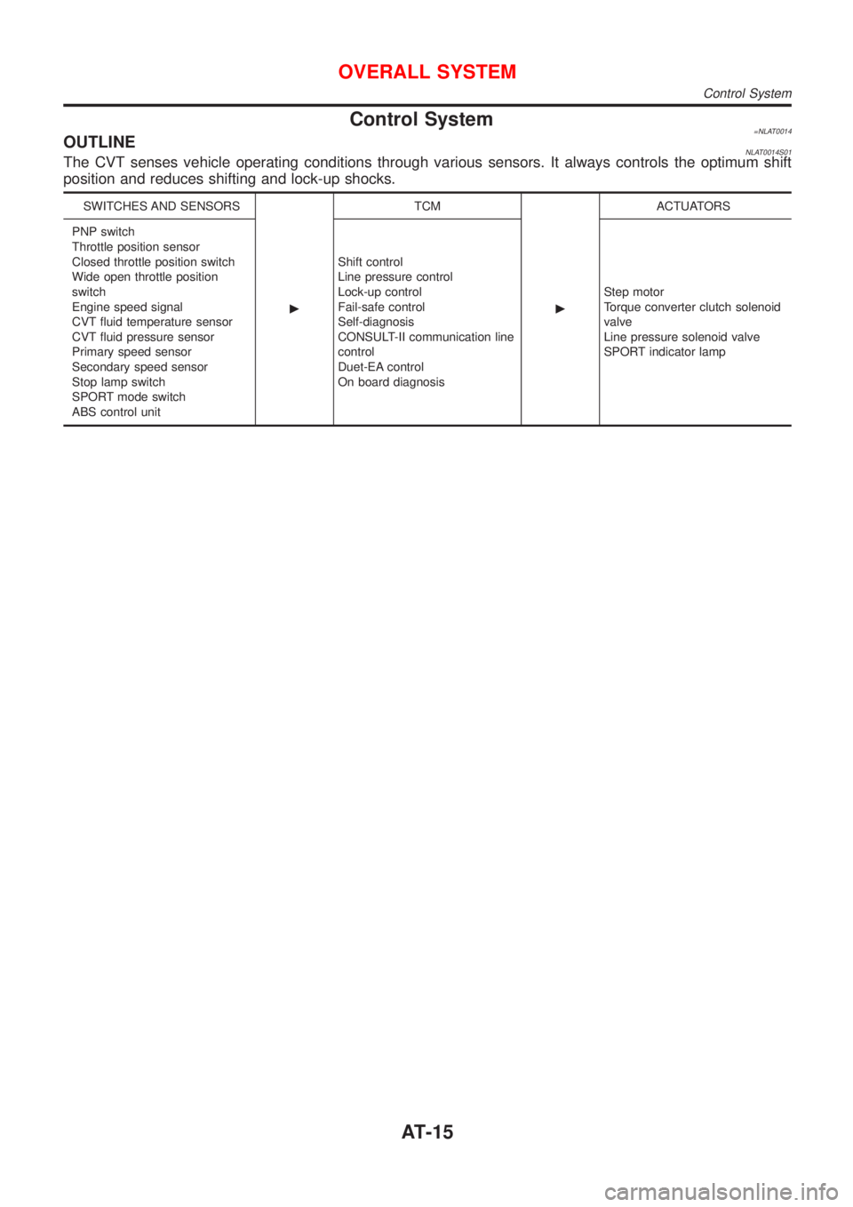
Control System=NLAT0014OUTLINENLAT0014S01The CVT senses vehicle operating conditions through various sensors. It always controls the optimum shift
position and reduces shifting and lock-up shocks.
SWITCHES AND SENSORS
cTCM
cACTUATORS
PNP switch
Throttle position sensor
Closed throttle position switch
Wide open throttle position
switch
Engine speed signal
CVT fluid temperature sensor
CVT fluid pressure sensor
Primary speed sensor
Secondary speed sensor
Stop lamp switch
SPORT mode switch
ABS control unitShift control
Line pressure control
Lock-up control
Fail-safe control
Self-diagnosis
CONSULT-II communication line
control
Duet-EA control
On board diagnosisStep motor
Torque converter clutch solenoid
valve
Line pressure solenoid valve
SPORT indicator lamp
OVERALL SYSTEM
Control System
AT-15
Page 18 of 3051

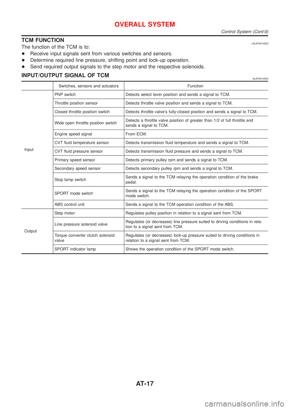
TCM FUNCTION=NLAT0014S03The function of the TCM is to:
+Receive input signals sent from various switches and sensors.
+Determine required line pressure, shifting point and lock-up operation.
+Send required output signals to the step motor and the respective solenoids.
INPUT/OUTPUT SIGNAL OF TCMNLAT0014S04
Switches, sensors and actuators Function
InputPNP switch Detects select lever position and sends a signal to TCM.
Throttle position sensor Detects throttle valve position and sends a signal to TCM.
Closed throttle position switch Detects throttle valve's fully-closed position and sends a signal to TCM.
Wide open throttle position switchDetects a throttle valve position of greater than 1/2 of full throttle and
sends a signal to TCM.
Engine speed signal From ECM.
CVT fluid temperature sensor Detects transmission fluid temperature and sends a signal to TCM.
CVT fluid pressure sensor Detects transmission fluid pressure and sends a signal to TCM.
Primary speed sensor Detects primary pulley rpm and sends a signal to TCM.
Secondary speed sensor Detects secondary pulley rpm and sends a signal to TCM.
Stop lamp switchSends a signal to the TCM relaying the operation condition of the brake
pedal.
SPORT mode switchSends a signal to the TCM relaying the operation condition of the SPORT
mode switch.
ABS control unit Sends a signal to the TCM operation condition of the ABS.
OutputStep motor Regulates pulley position in relation to a signal sent from TCM.
Line pressure solenoid valveRegulates (or decreases) line pressure suited to driving conditions in rela-
tion to a signal sent from TCM.
Torque converter clutch solenoid
valveRegulates (or decreases) lock-up pressure suited to driving conditions in
relation to a signal sent from TCM.
SPORT indicator lamp Shows the operation condition of the SPORT mode switch.
OVERALL SYSTEM
Control System (Cont'd)
AT-17