Page 59 of 3051
SAT216J
TCM Terminals and Reference ValueNLAT0030PREPARATIONNLAT0030S01+Measure voltage between each terminal and terminal 25 or 48
by following ªTCM INSPECTION TABLEº.
TCM HARNESS CONNECTOR TERMINAL LAYOUTNLAT0030S02
SAT403JA
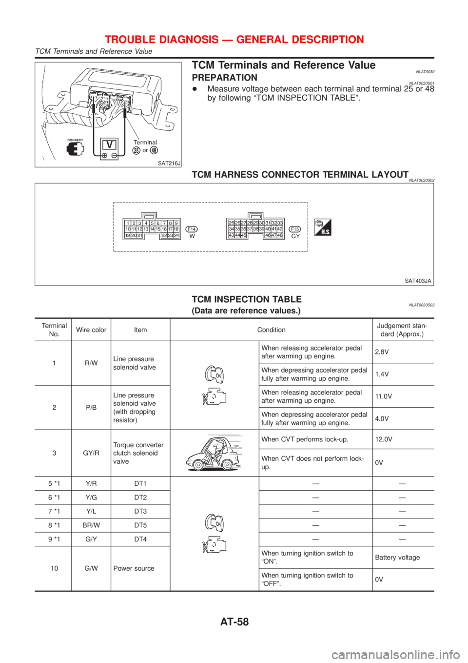
TCM INSPECTION TABLENLAT0030S03(Data are reference values.)
Terminal
No.Wire color Item ConditionJudgement stan-
dard (Approx.)
1 R/WLine pressure
solenoid valve
When releasing accelerator pedal
after warming up engine.2.8V
When depressing accelerator pedal
fully after warming up engine.1.4V
2 P/BLine pressure
solenoid valve
(with dropping
resistor)When releasing accelerator pedal
after warming up engine.11.0V
When depressing accelerator pedal
fully after warming up engine.4.0V
3 GY/RTorque converter
clutch solenoid
valve
When CVT performs lock-up. 12.0V
When CVT does not perform lock-
up.0V
5 *1 Y/R DT1
ÐÐ
6 *1 Y/G DT2 Ð Ð
7 *1 Y/L DT3 Ð Ð
8 *1 BR/W DT5 Ð Ð
9 *1 G/Y DT4 Ð Ð
10 G/W Power sourceWhen turning ignition switch to
ªONº.Battery voltage
When turning ignition switch to
ªOFFº.0V
TROUBLE DIAGNOSIS Ð GENERAL DESCRIPTION
TCM Terminals and Reference Value
AT-58
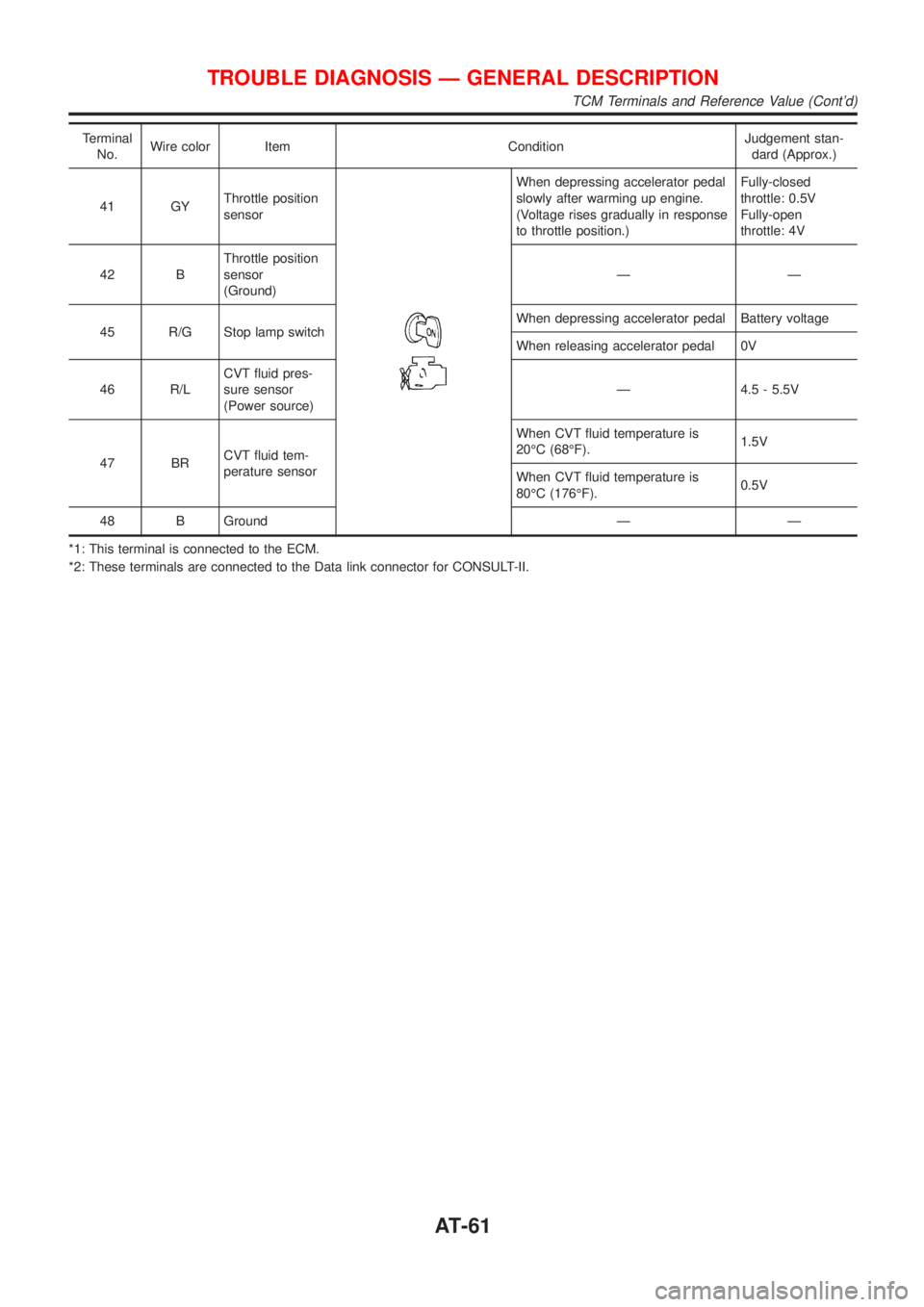
Page 60 of 3051
Terminal
No.Wire color Item ConditionJudgement stan-
dard (Approx.)
11 P UStep motor A Within 2 seconds after key switch ªONº, the time measurement by
using the pulse width measurement function (Hi level) of CON-
SULT-II.
+CONSULT-II cable connected to data link connector.
+This inspection cannot be measured by circuit tester.30.0 msec
12 L/W Step motor B10.0 msec
13 OR/BSPORT indicator
lamp
When SPORT indicator lamp illumi-
nates0V
When SPORT indicator lamp does
not illuminateBattery voltage
15 *1 PU (EURO-OBD-II) Ð Ð
16 Y/PUClosed throttle
position switch
(in throttle posi-
tion switch)When releasing accelerator pedal
after warming up engine.
Refer to step 1 to 6 of
ªPreparationº, ªTCM Self-diagnostic
Procedure (No Tools)º, AT-28 Ð
EURO-OBD/AT-35 Ð Except for
EURO-OBD.Battery voltage
When depressing accelerator pedal
after warming up engine.
Refer to step 1 to 6 of
ªPreparationº, ªTCM Self-diagnostic
Procedure (No Tools)º, AT-28 Ð
EURO-OBD/AT-35 Ð Except for
EURO-OBD.0V
17 LGWide open
throttle position
switch
(in throttle posi-
tion switch)When depressing accelerator pedal
more than half-way after warming
up engine.Battery voltage
When releasing accelerator pedal
after warming up engine.0V
18 BR ABS control unit
When driving slowly.Change 0V to
battery voltage
19 G/W Power source
Same as No. 10
20 L/Y Step motor CWithin 2 seconds after key switch ªONº, the time measurement by
using the pulse width measurement function (Hi level) of CON-
SULT-II.
+CONSULT-II cable connected to data link connector.
+This inspection cannot be measured by circuit tester.30.0 msec
21 P/L Step motor D10.0 msec
22 PSport mode
switch
When SPORT mode switch in ªONº
position.0V
When SPORT mode switch in
ªOFFº position.10V
23 SB ABS control unit
When ABS operates. 0V
When ABS does not operate. 5.6 - 10.0V
TROUBLE DIAGNOSIS Ð GENERAL DESCRIPTION
TCM Terminals and Reference Value (Cont'd)
AT-59
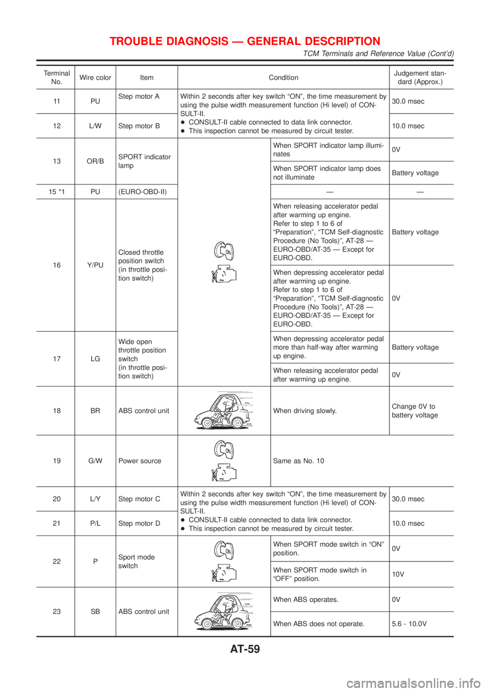
Page 61 of 3051
Terminal
No.Wire color Item ConditionJudgement stan-
dard (Approx.)
25 B Ground
ÐÐ
27 LPNP switch ªLº
positionWhen setting selector lever to ªLº
position.Battery voltage
When setting selector lever to other
positions.0V
28 R/BPower source
(Memory back-up)
or
When turning ignition switch to
ªOFFº.Battery voltage
When turning ignition switch to
ªONº.Battery voltage
29 G/RSecondary speed
sensorWhen driving [D position, 20 km/h (12 MPH)], the pulse measure-
ment by using the pulse measurement function of CONSULT-II.
+CONSULT-II cable connected to data link connector.
+This inspection cannot be measured by circuit tester.600 Hz
30 *2 G/B (RX)
ÐÐ
31 *2 GY/L (TX) Ð Ð
32 RThrottle position
sensor
(Power source)When turning ignition switch to ªONº 4.5 - 5.5V
When turning ignition switch to
ªOFFº0V
34 W/GPNP switch ªDº
positionWhen setting selector lever to ªDº
position.Battery voltage
When setting selector lever to other
positions.0V
35 G/WPNP switch ªRº
positionWhen setting selector lever to ªRº
position.Battery voltage
When setting selector lever to other
positions.0V
36 GPNP switch ªNº or
ªPº positionWhen setting selector lever to ªNº or
ªPº position.Battery voltage
When setting selector lever to other
positions.0V
37 WCVT fluid pres-
sure sensor
When engine runs at idle speed. 1.0V
When engine runs at stoll speed. 4.0V
38 G/YPrimary speed
sensorWhen driving [L position, 20 km/h (12 MPH)], the pulse measure-
ment by using the pulse measurement function of CONSULT-II.
+CONSULT-II cable connected to data link connector.
+This inspection cannot be measured by circuit tester.900 Hz
39 L/OREngine speed
signal
When engine runs at idle speed. 0.5 - 1.5V
TROUBLE DIAGNOSIS Ð GENERAL DESCRIPTION
TCM Terminals and Reference Value (Cont'd)
AT-60
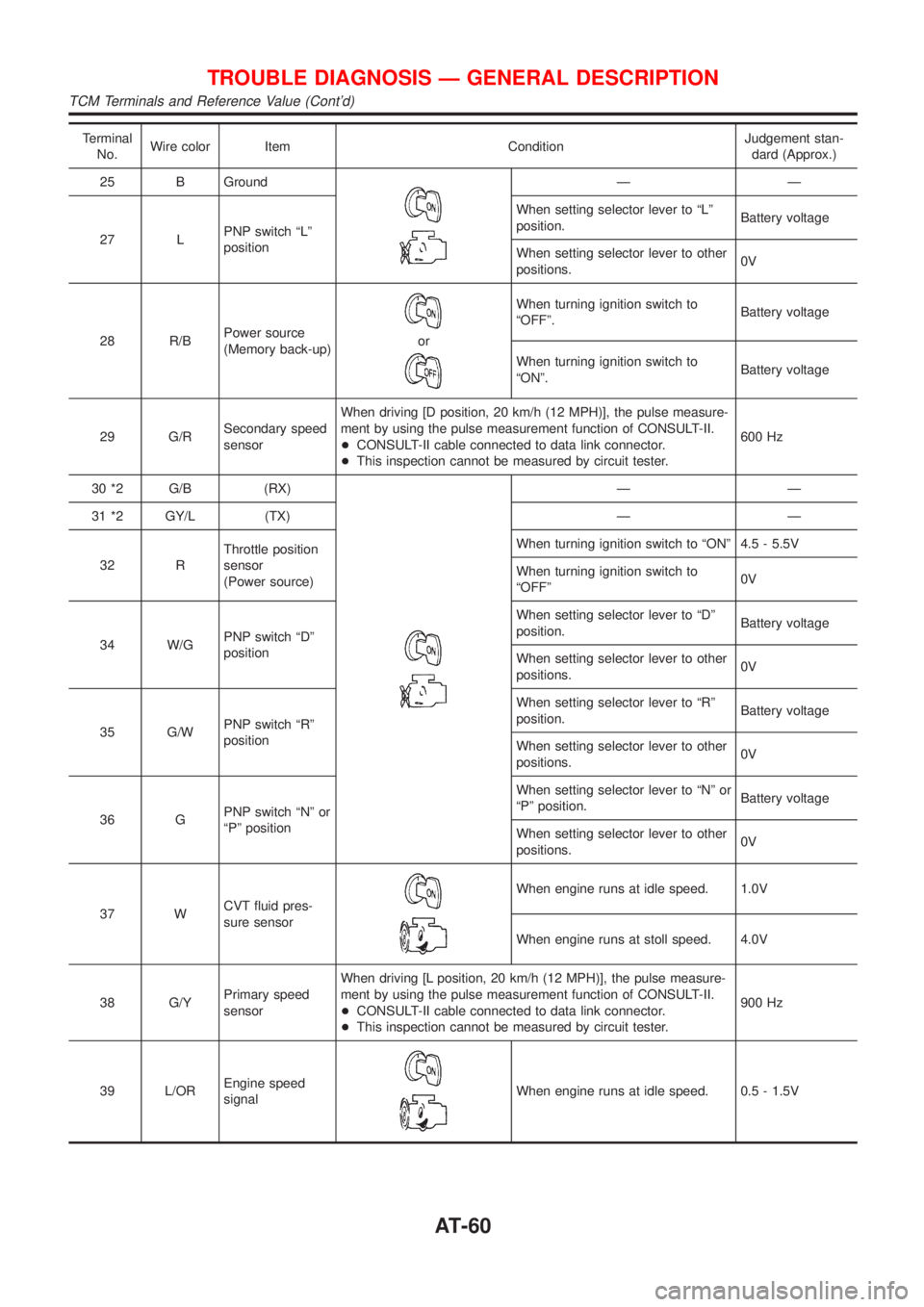
Page 62 of 3051
Terminal
No.Wire color Item ConditionJudgement stan-
dard (Approx.)
41 GYThrottle position
sensor
When depressing accelerator pedal
slowly after warming up engine.
(Voltage rises gradually in response
to throttle position.)Fully-closed
throttle: 0.5V
Fully-open
throttle: 4V
42 BThrottle position
sensor
(Ground)ÐÐ
45 R/G Stop lamp switchWhen depressing accelerator pedal Battery voltage
When releasing accelerator pedal 0V
46 R/LCVT fluid pres-
sure sensor
(Power source)Ð 4.5 - 5.5V
47 BRCVT fluid tem-
perature sensorWhen CVT fluid temperature is
20ÉC (68ÉF).1.5V
When CVT fluid temperature is
80ÉC (176ÉF).0.5V
48 B Ground Ð Ð
*1: This terminal is connected to the ECM.
*2: These terminals are connected to the Data link connector for CONSULT-II.
TROUBLE DIAGNOSIS Ð GENERAL DESCRIPTION
TCM Terminals and Reference Value (Cont'd)
AT-61
Page 63 of 3051
Wiring Diagram Ð AT Ð MAINNLAT0031MODELS WITH ECM IN ENGINE COMPARTMENTNLAT0031S01
YAT173
TROUBLE DIAGNOSIS FOR POWER SUPPLY
Wiring Diagram Ð AT Ð MAIN
AT-62
Page 66 of 3051
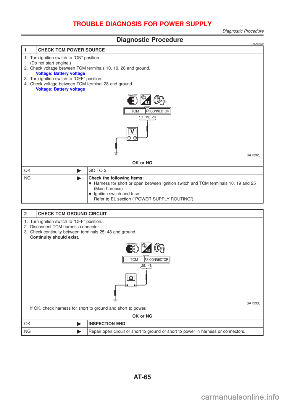
Diagnostic ProcedureNLAT0330
1 CHECK TCM POWER SOURCE
1. Turn ignition switch to ªONº position.
(Do not start engine.)
2. Check voltage between TCM terminals 10, 19, 28 and ground.
Voltage: Battery voltage
3. Turn ignition switch to ªOFFº position.
4. Check voltage between TCM terminal 28 and ground.
Voltage: Battery voltage
SAT332J
OK or NG
OK©GO TO 2.
NG©Check the following items:
+Harness for short or open between ignition switch and TCM terminals 10, 19 and 25
(Main harness)
+Ignition switch and fuse
Refer to EL section (ªPOWER SUPPLY ROUTINGº).
2 CHECK TCM GROUND CIRCUIT
1. Turn ignition switch to ªOFFº position.
2. Disconnect TCM harness connector.
3. Check continuity between terminals 25, 48 and ground.
Continuity should exist.
SAT333J
If OK, check harness for short to ground and short to power.
OK or NG
OK©INSPECTION END
NG©Repair open circuit or short to ground or short to power in harness or connectors.
TROUBLE DIAGNOSIS FOR POWER SUPPLY
Diagnostic Procedure
AT-65
Page 68 of 3051

SAT250K
SAT255K
DIAGNOSTIC TROUBLE CODE (DTC) CONFIRMATION
PROCEDURE
NLAT0032S03CAUTION:
Always drive vehicle at a safe speed.
NOTE:
If ªDIAGNOSTIC TROUBLE CODE CONFIRMATION PROCE-
DUREº has been previously conducted, always turn ignition
switch ªOFFº and wait at least 5 seconds before conducting
the next test.
After the repair, perform the following procedure to confirm the
malfunction is eliminated.
With CONSULT-II
1) Turn ignition switch ªONº and select ªDATA MONITORº mode
for ªCVTº with CONSULT-II.
2) Make sure that output voltage of CVT fluid temperature sen-
sor is within the range below.
FLUID TEMP SEN: 0.5 - 1.5V
If out of range, drive the vehicle to decrease the voltage
(warm up the fluid) or stop engine to increase the voltage
(cool down the fluid)
3) Select ªDATA MONITORº mode for ªENGINEº with CONSULT-
II.
4) Start engine and maintain the following conditions for at least
15 consecutive seconds.
VHCL SPEED SE: 10 km/h (6 MPH) or more
THRTL POS SEN: More than 1.0/8
Selector lever: D position
ENG SPEED: 450 rpm or more
If the check result is ªNGº, go to ªDiagnostic Procedureº, AT-70.
With GST
Follow the procedure ªWith CONSULT-IIº.
DTC P0705 PARK/NEUTRAL POSITION (PNP) SWITCHEURO-OBD
Description (Cont'd)
AT-67
Page 69 of 3051
Wiring Diagram Ð AT Ð PNP/SWNLAT0199MODELS WITH ECM IN ENGINE COMPARTMENTNLAT0199S01
YAT174
DTC P0705 PARK/NEUTRAL POSITION (PNP) SWITCHEURO-OBD
Wiring Diagram Ð AT Ð PNP/SW
AT-68