2001 NISSAN ALMERA TINO towing
[x] Cancel search: towingPage 1896 of 3051

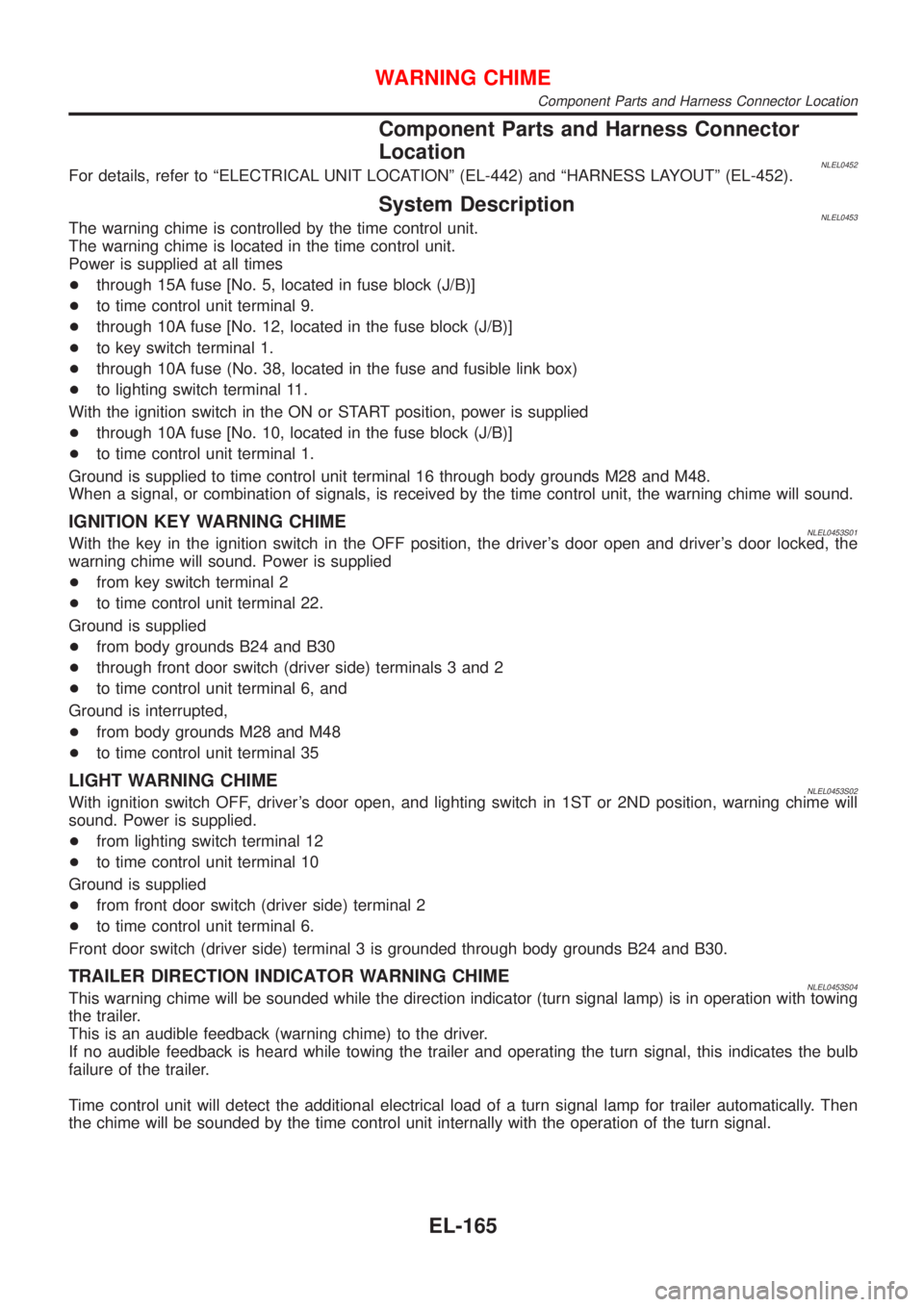
Component Parts and Harness Connector
Location
NLEL0452For details, refer to ªELECTRICAL UNIT LOCATIONº (EL-442) and ªHARNESS LAYOUTº (EL-452).
System DescriptionNLEL0453The warning chime is controlled by the time control unit.
The warning chime is located in the time control unit.
Power is supplied at all times
+through 15A fuse [No. 5, located in fuse block (J/B)]
+to time control unit terminal 9.
+through 10A fuse [No. 12, located in the fuse block (J/B)]
+to key switch terminal 1.
+through 10A fuse (No. 38, located in the fuse and fusible link box)
+to lighting switch terminal 11.
With the ignition switch in the ON or START position, power is supplied
+through 10A fuse [No. 10, located in the fuse block (J/B)]
+to time control unit terminal 1.
Ground is supplied to time control unit terminal 16 through body grounds M28 and M48.
When a signal, or combination of signals, is received by the time control unit, the warning chime will sound.
IGNITION KEY WARNING CHIMENLEL0453S01With the key in the ignition switch in the OFF position, the driver's door open and driver's door locked, the
warning chime will sound. Power is supplied
+from key switch terminal 2
+to time control unit terminal 22.
Ground is supplied
+from body grounds B24 and B30
+through front door switch (driver side) terminals 3 and 2
+to time control unit terminal 6, and
Ground is interrupted,
+from body grounds M28 and M48
+to time control unit terminal 35
LIGHT WARNING CHIMENLEL0453S02With ignition switch OFF, driver's door open, and lighting switch in 1ST or 2ND position, warning chime will
sound. Power is supplied.
+from lighting switch terminal 12
+to time control unit terminal 10
Ground is supplied
+from front door switch (driver side) terminal 2
+to time control unit terminal 6.
Front door switch (driver side) terminal 3 is grounded through body grounds B24 and B30.
TRAILER DIRECTION INDICATOR WARNING CHIMENLEL0453S04This warning chime will be sounded while the direction indicator (turn signal lamp) is in operation with towing
the trailer.
This is an audible feedback (warning chime) to the driver.
If no audible feedback is heard while towing the trailer and operating the turn signal, this indicates the bulb
failure of the trailer.
Time control unit will detect the additional electrical load of a turn signal lamp for trailer automatically. Then
the chime will be sounded by the time control unit internally with the operation of the turn signal.
WARNING CHIME
Component Parts and Harness Connector Location
EL-165
Page 2057 of 3051

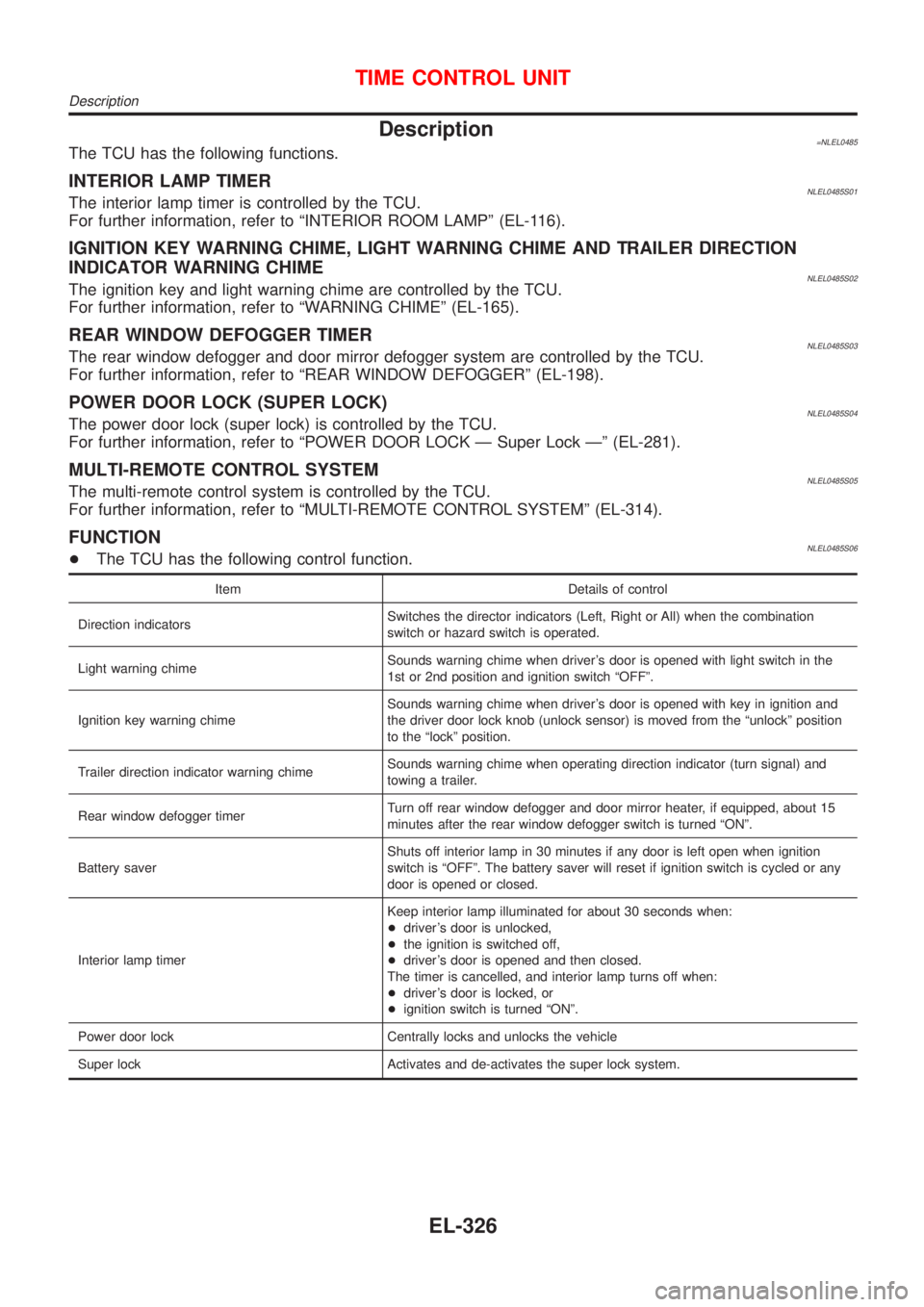
Description=NLEL0485The TCU has the following functions.
INTERIOR LAMP TIMERNLEL0485S01The interior lamp timer is controlled by the TCU.
For further information, refer to ªINTERIOR ROOM LAMPº (EL-116).
IGNITION KEY WARNING CHIME, LIGHT WARNING CHIME AND TRAILER DIRECTION
INDICATOR WARNING CHIME
NLEL0485S02The ignition key and light warning chime are controlled by the TCU.
For further information, refer to ªWARNING CHIMEº (EL-165).
REAR WINDOW DEFOGGER TIMERNLEL0485S03The rear window defogger and door mirror defogger system are controlled by the TCU.
For further information, refer to ªREAR WINDOW DEFOGGERº (EL-198).
POWER DOOR LOCK (SUPER LOCK)NLEL0485S04The power door lock (super lock) is controlled by the TCU.
For further information, refer to ªPOWER DOOR LOCK Ð Super Lock к (EL-281).
MULTI-REMOTE CONTROL SYSTEMNLEL0485S05The multi-remote control system is controlled by the TCU.
For further information, refer to ªMULTI-REMOTE CONTROL SYSTEMº (EL-314).
FUNCTIONNLEL0485S06+The TCU has the following control function.
Item Details of control
Direction indicatorsSwitches the director indicators (Left, Right or All) when the combination
switch or hazard switch is operated.
Light warning chimeSounds warning chime when driver's door is opened with light switch in the
1st or 2nd position and ignition switch ªOFFº.
Ignition key warning chimeSounds warning chime when driver's door is opened with key in ignition and
the driver door lock knob (unlock sensor) is moved from the ªunlockº position
to the ªlockº position.
Trailer direction indicator warning chimeSounds warning chime when operating direction indicator (turn signal) and
towing a trailer.
Rear window defogger timerTurn off rear window defogger and door mirror heater, if equipped, about 15
minutes after the rear window defogger switch is turned ªONº.
Battery saverShuts off interior lamp in 30 minutes if any door is left open when ignition
switch is ªOFFº. The battery saver will reset if ignition switch is cycled or any
door is opened or closed.
Interior lamp timerKeep interior lamp illuminated for about 30 seconds when:
+driver's door is unlocked,
+the ignition is switched off,
+driver's door is opened and then closed.
The timer is cancelled, and interior lamp turns off when:
+driver's door is locked, or
+ignition switch is turned ªONº.
Power door lock Centrally locks and unlocks the vehicle
Super lock Activates and de-activates the super lock system.
TIME CONTROL UNIT
Description
EL-326
Page 2540 of 3051

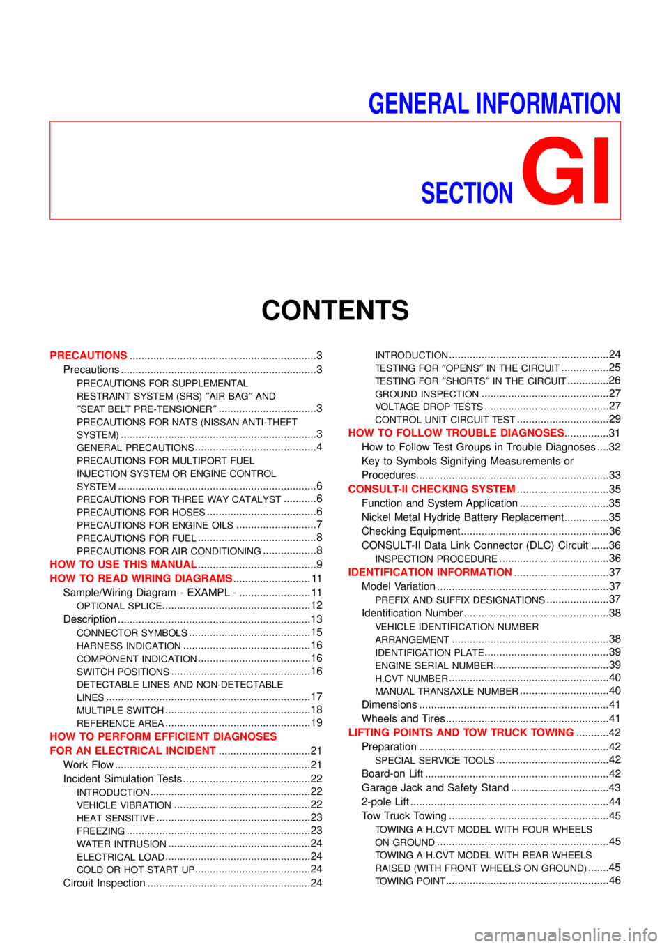
GENERAL INFORMATION
SECTION
GI
CONTENTS
PRECAUTIONS...............................................................3
Precautions ..................................................................3
PRECAUTIONS FOR SUPPLEMENTAL
RESTRAINT SYSTEM (SRS)″AIR BAG″AND
″SEAT BELT PRE-TENSIONER″
.................................3
PRECAUTIONS FOR NATS (NISSAN ANTI-THEFT
SYSTEM)
..................................................................3
GENERAL PRECAUTIONS.........................................4
PRECAUTIONS FOR MULTIPORT FUEL
INJECTION SYSTEM OR ENGINE CONTROL
SYSTEM
...................................................................6
PRECAUTIONS FOR THREE WAY CATALYST...........6
PRECAUTIONS FOR HOSES.....................................6
PRECAUTIONS FOR ENGINE OILS...........................7
PRECAUTIONS FOR FUEL........................................8
PRECAUTIONS FOR AIR CONDITIONING..................8
HOW TO USE THIS MANUAL........................................9
HOW TO READ WIRING DIAGRAMS.......................... 11
Sample/Wiring Diagram - EXAMPL - ........................ 11
OPTIONAL SPLICE..................................................12
Description .................................................................13
CONNECTOR SYMBOLS.........................................15
HARNESS INDICATION...........................................16
COMPONENT INDICATION......................................16
SWITCH POSITIONS...............................................16
DETECTABLE LINES AND NON-DETECTABLE
LINES
.....................................................................17
MULTIPLE SWITCH.................................................18
REFERENCE AREA.................................................19
HOW TO PERFORM EFFICIENT DIAGNOSES
FOR AN ELECTRICAL INCIDENT...............................21
Work Flow ..................................................................21
Incident Simulation Tests ...........................................22
INTRODUCTION......................................................22
VEHICLE VIBRATION..............................................22
HEAT SENSITIVE....................................................23
FREEZING..............................................................23
WATER INTRUSION................................................24
ELECTRICAL LOAD.................................................24
COLD OR HOT START UP.......................................24
Circuit Inspection .......................................................24
INTRODUCTION......................................................24
TESTING FOR″OPENS″IN THE CIRCUIT................25
TESTING FOR″SHORTS″IN THE CIRCUIT..............26
GROUND INSPECTION...........................................27
VOLTAGE DROP TESTS..........................................27
CONTROL UNIT CIRCUIT TEST...............................29
HOW TO FOLLOW TROUBLE DIAGNOSES...............31
How to Follow Test Groups in Trouble Diagnoses ....32
Key to Symbols Signifying Measurements or
Procedures.................................................................33
CONSULT-II CHECKING SYSTEM...............................35
Function and System Application ..............................35
Nickel Metal Hydride Battery Replacement...............35
Checking Equipment..................................................36
CONSULT-II Data Link Connector (DLC) Circuit ......36
INSPECTION PROCEDURE.....................................36
IDENTIFICATION INFORMATION................................37
Model Variation ..........................................................37
PREFIX AND SUFFIX DESIGNATIONS.....................37
Identification Number .................................................38
VEHICLE IDENTIFICATION NUMBER
ARRANGEMENT
.....................................................38
IDENTIFICATION PLATE..........................................39
ENGINE SERIAL NUMBER.......................................39
H.CVT NUMBER......................................................40
MANUAL TRANSAXLE NUMBER..............................40
Dimensions ................................................................41
Wheels and Tires .......................................................41
LIFTING POINTS AND TOW TRUCK TOWING...........42
Preparation ................................................................42
SPECIAL SERVICE TOOLS......................................42
Board-on Lift ..............................................................42
Garage Jack and Safety Stand .................................43
2-pole Lift ...................................................................44
Tow Truck Towing ......................................................45
TOWING A H.CVT MODEL WITH FOUR WHEELS
ON GROUND
..........................................................45
TOWING A H.CVT MODEL WITH REAR WHEELS
RAISED (WITH FRONT WHEELS ON GROUND)
.......45
TOWING POINT.......................................................46
Page 2581 of 3051

NLGI0009
PreparationNLGI0009S01SPECIAL SERVICE TOOLSNLGI0009S0101
Tool number
Tool nameDescription
LM4086-0200
Board on attachment
NT001
LM4519-0000
Safety stand attachment
NT002
AGI016
Board-on LiftNLGI0009S02CAUTION:
Make sure vehicle is empty when lifting.
+The board-on lift attachment (LM4086-0200) set at front
end of vehicle should be set on the front of the sill under
the front door opening.
+Position attachments at front and rear ends of board-on
lift.
LIFTING POINTS AND TOW TRUCK TOWING
Preparation
GI-42
Page 2582 of 3051

Garage Jack and Safety Stand=NLGI0009S03WARNING:
+Never get under the vehicle while it is supported only by
the jack. Always use safety stands when you have to get
under the vehicle.
+Place wheel chocks at both front and back of the wheels
on the ground.
SGI110A
LIFTING POINTS AND TOW TRUCK TOWING
Garage Jack and Safety Stand
GI-43
Page 2583 of 3051

2-pole Lift=NLGI0009S04WARNING:
When lifting the vehicle, open the lift arms as wide as possible
and ensure that the front and rear of the vehicle are well bal-
anced.
When setting the lift arm, do not allow the arm to contact the
brake tubes, brake cable, fuel lines and sill spoiler.
SGI111A
LIFTING POINTS AND TOW TRUCK TOWING
2-pole Lift
GI-44
Page 2584 of 3051

SGI805
NGI058
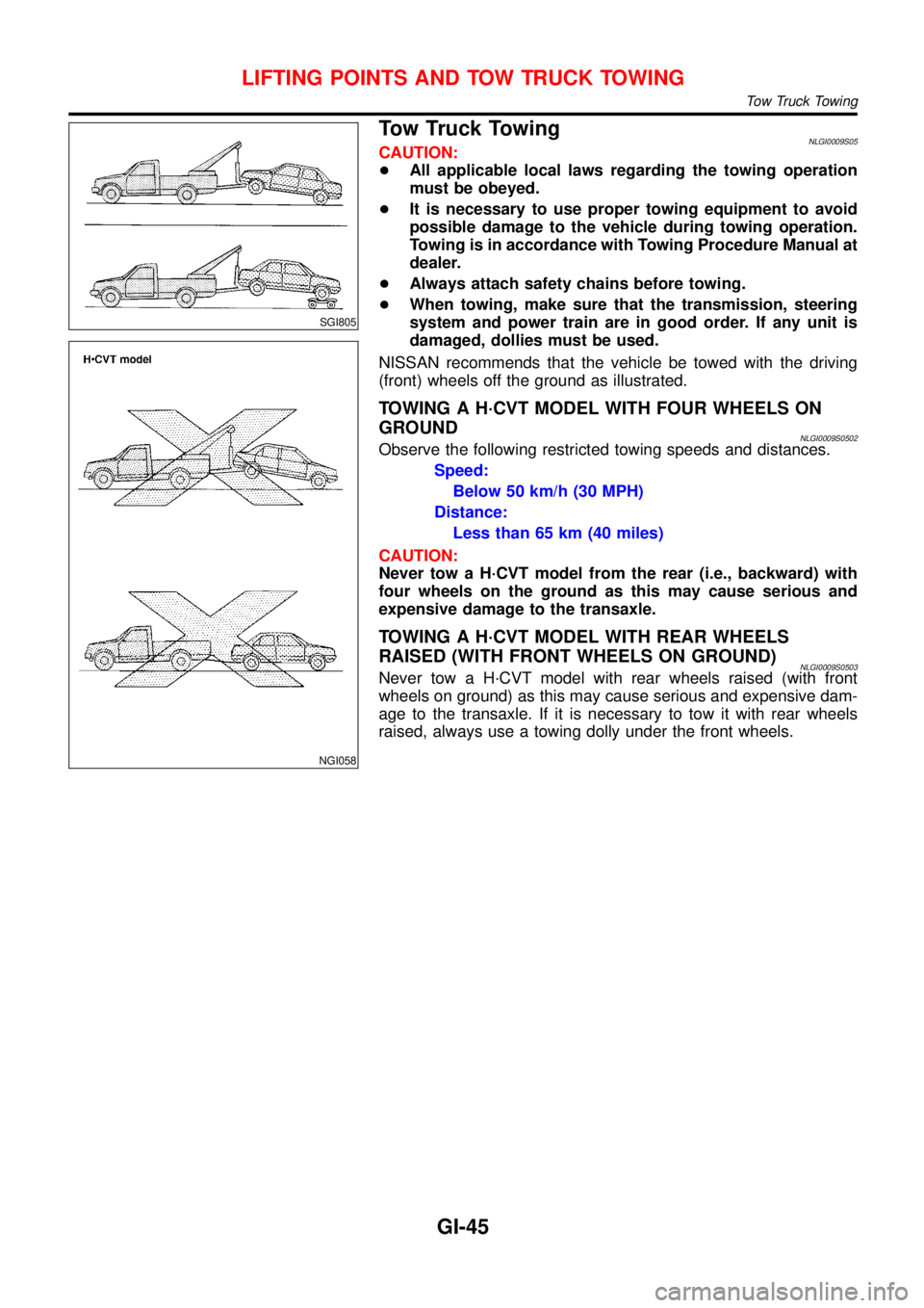
Tow Truck TowingNLGI0009S05CAUTION:
+All applicable local laws regarding the towing operation
must be obeyed.
+It is necessary to use proper towing equipment to avoid
possible damage to the vehicle during towing operation.
Towing is in accordance with Towing Procedure Manual at
dealer.
+Always attach safety chains before towing.
+When towing, make sure that the transmission, steering
system and power train are in good order. If any unit is
damaged, dollies must be used.
NISSAN recommends that the vehicle be towed with the driving
(front) wheels off the ground as illustrated.
TOWING A H·CVT MODEL WITH FOUR WHEELS ON
GROUND
NLGI0009S0502Observe the following restricted towing speeds and distances.
Speed:
Below 50 km/h (30 MPH)
Distance:
Less than 65 km (40 miles)
CAUTION:
Never tow a H·CVT model from the rear (i.e., backward) with
four wheels on the ground as this may cause serious and
expensive damage to the transaxle.
TOWING A H·CVT MODEL WITH REAR WHEELS
RAISED (WITH FRONT WHEELS ON GROUND)
NLGI0009S0503Never tow a H·CVT model with rear wheels raised (with front
wheels on ground) as this may cause serious and expensive dam-
age to the transaxle. If it is necessary to tow it with rear wheels
raised, always use a towing dolly under the front wheels.
LIFTING POINTS AND TOW TRUCK TOWING
Tow Truck Towing
GI-45
Page 2585 of 3051

TOWING POINT=NLGI0009S0501
NGI056
NGI057
Always pull the cable straight out from the vehicle. Never pull
on the hook at a sideways angle.
LIFTING POINTS AND TOW TRUCK TOWING
Tow Truck Towing (Cont’d)
GI-46