2001 NISSAN ALMERA TINO wheel
[x] Cancel search: wheelPage 7 of 3051

Precautions for Supplemental Restraint System
(SRS) ªAIR BAGº and ªSEAT BELT
PRE-TENSIONERº
NLAT0002The Supplemental Restraint System ªAIR BAGº and ªSEAT BELT PRE-TENSIONERº, used along with a seat
belt, help to reduce the risk or severity of injury to the driver and front passenger in a frontal collision. The
Supplemental Restraint System consists of air bag modules (located in the center of the steering wheel and
on the instrument panel on the passenger side), seat belt pre-tensioners, a diagnosis sensor unit, warning
lamp, wiring harness and spiral cable.
In addition to the supplemental air bag modules for a frontal collision, the supplemental side air bag used along
with the seat belt helps to reduce the risk or severity of injury to the driver and front passenger in a side col-
lision. The supplemental side air bag consists of air bag modules (located in the outer side of front seats),
satellite sensor, diagnosis sensor unit (one of components of supplemental air bags for a frontal collision),
wiring harness, warning lamp (one of components of supplemental air bags for a frontal collision). Information
necessary to service the system safely is included in theRS sectionof this Service Manual.
WARNING:
+To avoid rendering the SRS inoperative, which could increase the risk of personal injury or death
in the event of a collision which would result in air bag inflation, all maintenance must be performed
by an authorized NISSAN dealer.
+Improper maintenance, including incorrect removal and installation of the SRS, can lead to per-
sonal injury caused by unintentional activation of the system.
+Do not use electrical test equipment on any circuit related to the SRS unless instructed to in this
Service Manual. SRS wiring harnesses can be identified with yellow harness connector (and with
yellow harness protector or yellow insulation tape before the harness connectors).
Precautions for On Board Diagnostic (EURO-
OBD) System of CVT and Engine
NLAT0198The ECM has an on board diagnostic system. It will light up the malfunction indicator lamp (MI) to warn the
driver of a malfunction causing emission deterioration.
CAUTION:
+Be sure to turn the ignition switch ªOFFº and disconnect the negative battery terminal before any
repair or inspection work. The open/short circuit of related switches, sensors, solenoid valves, etc.
will cause the MI to light up.
+Be sure to connect and lock the connectors securely after work. A loose (unlocked) connector will
cause the MI to light up due to an open circuit. (Be sure the connector is free from water, grease,
dirt, bent terminals, etc.)
+Be sure to route and secure the harnesses properly after work. Interference of the harness with a
bracket, etc. may cause the MI to light up due to a short circuit.
+Be sure to connect rubber tubes properly after work. A misconnected or disconnected rubber tube
may cause the MI to light up due to a malfunction of the EGR system or fuel injection system, etc.
+Be sure to erase the unnecessary malfunction information (repairs completed) from the TCM and
ECM before returning the vehicle to the customer.
SEF289H
PrecautionsNLAT0003+Before connecting or disconnecting the TCM harness
connector, turn ignition switch OFF and disconnect nega-
tive battery terminal. Failure to do so may damage the
TCM. Because battery voltage is applied to TCM even if
ignition switch is turned off.
PRECAUTIONS
Precautions for Supplemental Restraint System (SRS) ªAIR BAGº and ªSEAT BELT PRE-TENSIONERº
AT-6
Page 53 of 3051
SAT513G
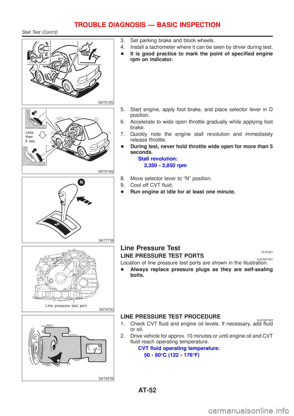
3. Set parking brake and block wheels.
4. Install a tachometer where it can be seen by driver during test.
+It is good practice to mark the point of specified engine
rpm on indicator.
SAT514G
5. Start engine, apply foot brake, and place selector lever in D
position.
6. Accelerate to wide open throttle gradually while applying foot
brake.
7. Quickly note the engine stall revolution and immediately
release throttle.
+During test, never hold throttle wide open for more than 5
seconds.
Stall revolution:
2,350 - 2,850 rpm
SAT771B
8. Move selector lever to ªNº position.
9. Cool off CVT fluid.
+Run engine at idle for at least one minute.
SAT670J
Line Pressure TestNLAT0027LINE PRESSURE TEST PORTSNLAT0027S01Location of line pressure test ports are shown in the illustration.
+Always replace pressure plugs as they are self-sealing
bolts.
SAT647B
LINE PRESSURE TEST PROCEDURENLAT0027S021. Check CVT fluid and engine oil levels. If necessary, add fluid
or oil.
2. Drive vehicle for approx. 10 minutes or until engine oil and CVT
fluid reach operating temperature.
CVT fluid operating temperature:
50 - 80ÉC (122 - 176ÉF)
TROUBLE DIAGNOSIS Ð BASIC INSPECTION
Stall Test (Cont'd)
AT-52
Page 54 of 3051
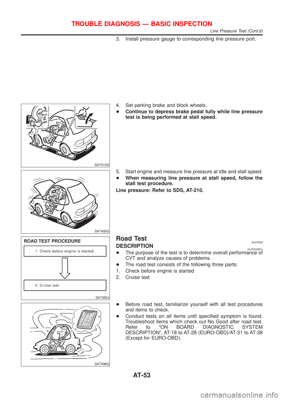
3. Install pressure gauge to corresponding line pressure port.
SAT513G
4. Set parking brake and block wheels.
+Continue to depress brake pedal fully while line pressure
test is being performed at stall speed.
SAT493G
5. Start engine and measure line pressure at idle and stall speed.
+When measuring line pressure at stall speed, follow the
stall test procedure.
Line pressure: Refer to SDS, AT-210.
SAT692J
Road TestNLAT0028DESCRIPTIONNLAT0028S01+The purpose of the test is to determine overall performance of
CVT and analyze causes of problems.
+The road test consists of the following three parts:
1. Check before engine is started
2. Cruise test
SAT496G
+Before road test, familiarize yourself with all test procedures
and items to check.
+Conduct tests on all items until specified symptom is found.
Troubleshoot items which check out No Good after road test.
Refer to ªON BOARD DIAGNOSTIC SYSTEM
DESCRIPTIONº, AT-18 to AT-28 (EURO-OBD)/AT-31 to AT-38
(Except for EURO-OBD).
TROUBLE DIAGNOSIS Ð BASIC INSPECTION
Line Pressure Test (Cont'd)
AT-53
Page 84 of 3051
SAT230K
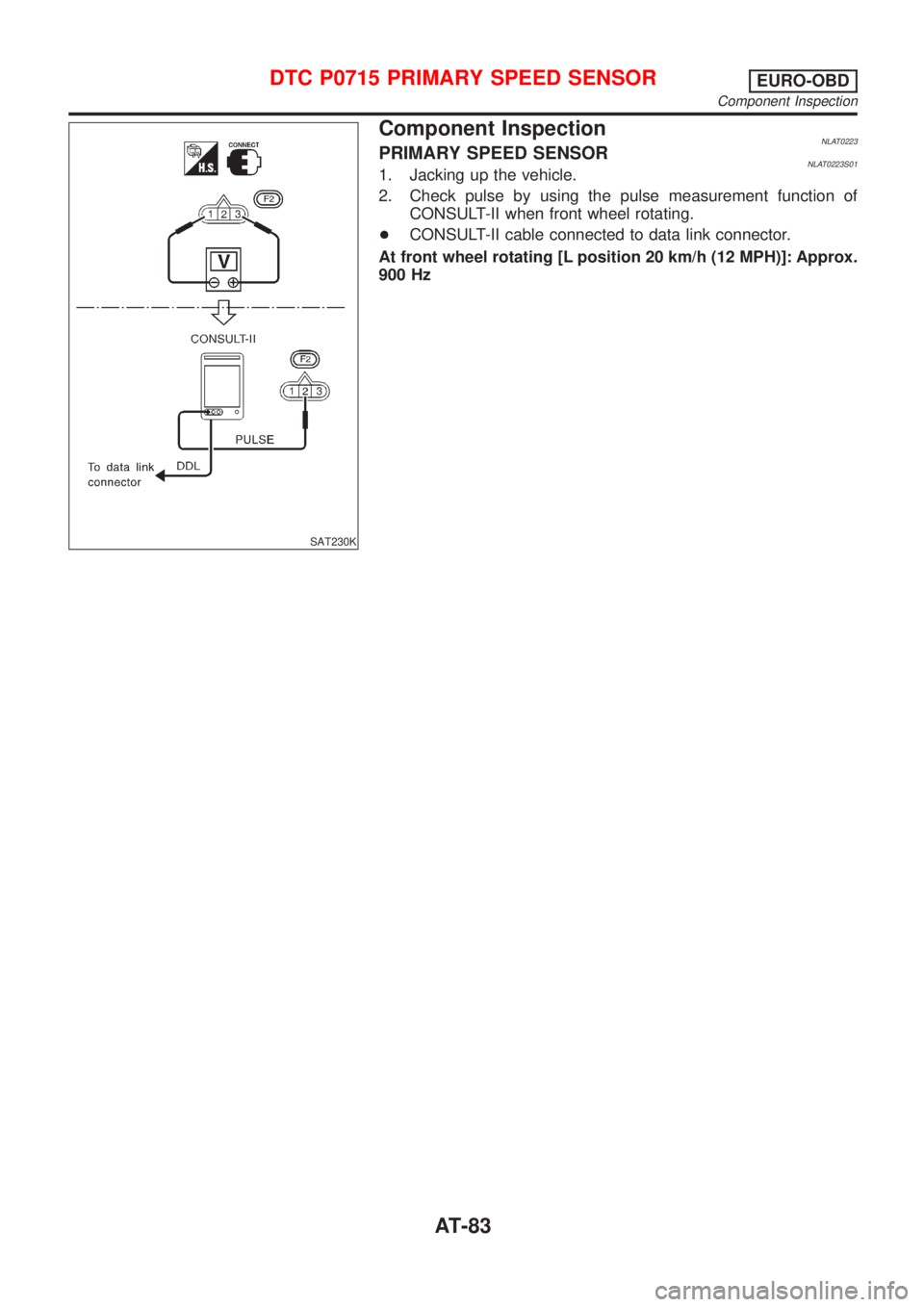
Component InspectionNLAT0223PRIMARY SPEED SENSORNLAT0223S011. Jacking up the vehicle.
2. Check pulse by using the pulse measurement function of
CONSULT-II when front wheel rotating.
+CONSULT-II cable connected to data link connector.
At front wheel rotating [L position 20 km/h (12 MPH)]: Approx.
900 Hz
DTC P0715 PRIMARY SPEED SENSOREURO-OBD
Component Inspection
AT-83
Page 90 of 3051

SAT231K
Component InspectionNLAT0040SECONDARY SPEED SENSORNLAT0040S011. Jacking up the vehicle.
2. Check pulse by using the pulse measurement function of
CONSULT-II when front wheel rotating.
+CONSULT-II cable connected to data link connector.
At front wheel rotating [D position, 20 km/h (12 MPH)]: Approx.
600 Hz
DTC P0720 VEHICLE SPEED SENSOR
(SECONDARY SPEED SENSOR)
EURO-OBD
Component Inspection
AT-89
Page 205 of 3051
SAT658J
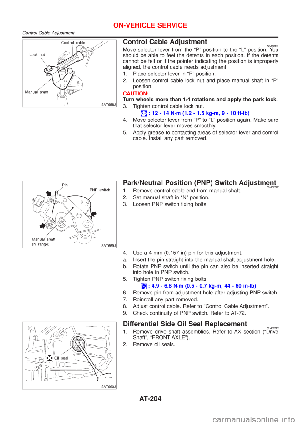
Control Cable AdjustmentNLAT0111Move selector lever from the ªPº position to the ªLº position. You
should be able to feel the detents in each position. If the detents
cannot be felt or if the pointer indicating the position is improperly
aligned, the control cable needs adjustment.
1. Place selector lever in ªPº position.
2. Loosen control cable lock nut and place manual shaft in ªPº
position.
CAUTION:
Turn wheels more than 1/4 rotations and apply the park lock.
3. Tighten control cable lock nut.
: 12 - 14 N´m (1.2 - 1.5 kg-m,9-10ft-lb)
4. Move selector lever from ªPº to ªLº position again. Make sure
that selector lever moves smoothly.
5. Apply grease to contacting areas of selector lever and control
cable. Install any part removed.
SAT659J
Park/Neutral Position (PNP) Switch AdjustmentNLAT01121. Remove control cable end from manual shaft.
2. Set manual shaft in ªNº position.
3. Loosen PNP switch fixing bolts.
4. Usea4mm(0.157 in) pin for this adjustment.
a. Insert the pin straight into the manual shaft adjustment hole.
b. Rotate PNP switch until the pin can also be inserted straight
into hole in PNP switch.
5. Tighten PNP switch fixing bolts.
: 4.9 - 6.8 N´m (0.5 - 0.7 kg-m, 44 - 60 in-lb)
6. Remove pin from adjustment hole after adjusting PNP switch.
7. Reinstall any part removed.
8. Adjust control cable. Refer to ªControl Cable Adjustmentº.
9. Check continuity of PNP switch. Refer to AT-72.
SAT660J
Differential Side Oil Seal ReplacementNLAT01131. Remove drive shaft assemblies. Refer to AX section (ªDrive
Shaftº, ªFRONT AXLEº).
2. Remove oil seals.
ON-VEHICLE SERVICE
Control Cable Adjustment
AT-204
Page 212 of 3051
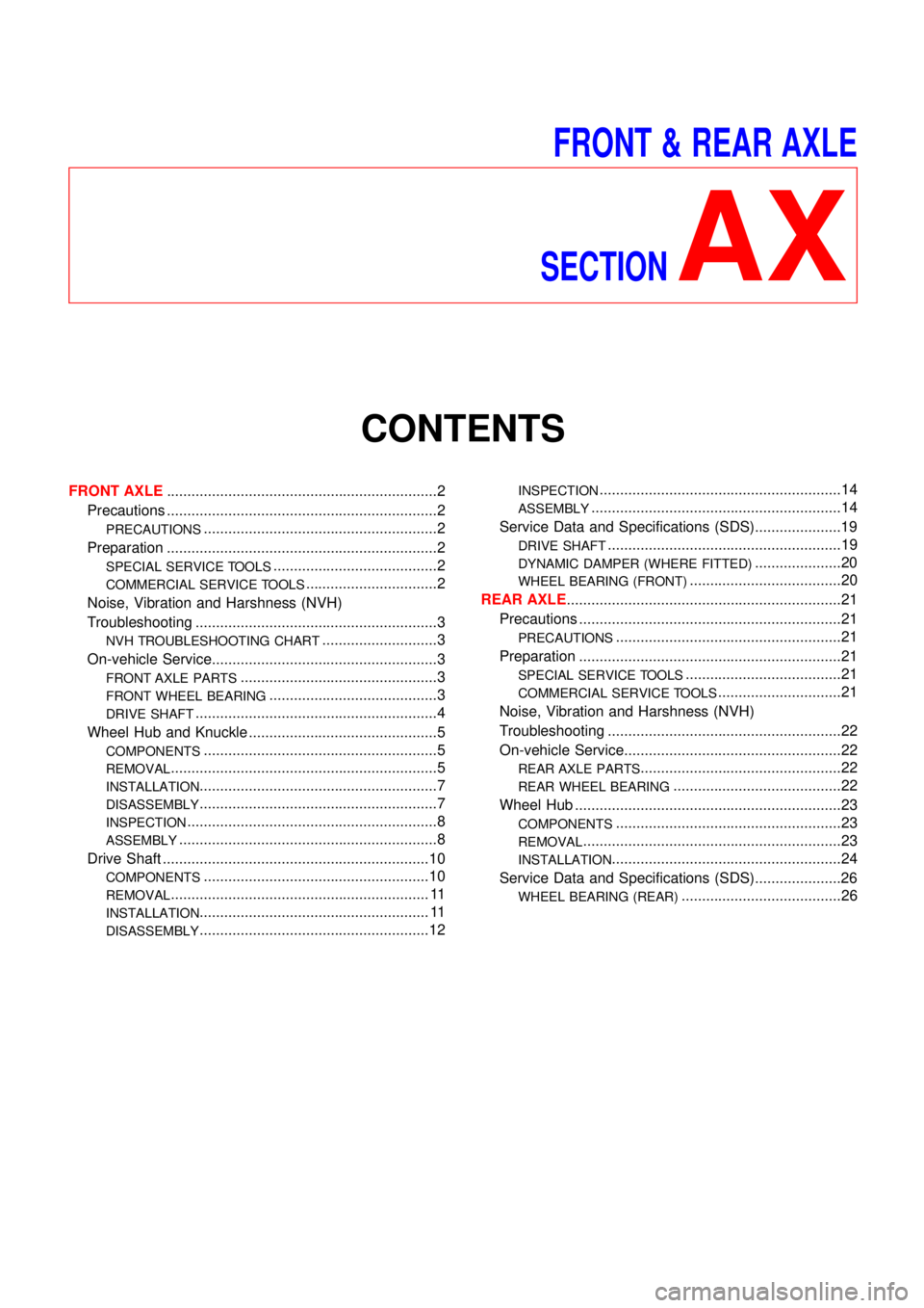
FRONT & REAR AXLE
SECTION
AX
CONTENTS
FRONT AXLE..................................................................2
Precautions ..................................................................2
PRECAUTIONS.........................................................2
Preparation ..................................................................2
SPECIAL SERVICE TOOLS........................................2
COMMERCIAL SERVICE TOOLS................................2
Noise, Vibration and Harshness (NVH)
Troubleshooting ...........................................................3
NVH TROUBLESHOOTING CHART............................3
On-vehicle Service.......................................................3
FRONT AXLE PARTS................................................3
FRONT WHEEL BEARING.........................................3
DRIVE SHAFT...........................................................4
Wheel Hub and Knuckle ..............................................5
COMPONENTS.........................................................5
REMOVAL.................................................................5
INSTALLATION..........................................................7
DISASSEMBLY..........................................................7
INSPECTION.............................................................8
ASSEMBLY...............................................................8
Drive Shaft .................................................................10
COMPONENTS.......................................................10
REMOVAL............................................................... 11
INSTALLATION........................................................ 11
DISASSEMBLY........................................................12
INSPECTION...........................................................14
ASSEMBLY.............................................................14
Service Data and Specifications (SDS).....................19
DRIVE SHAFT.........................................................19
DYNAMIC DAMPER (WHERE FITTED).....................20
WHEEL BEARING (FRONT).....................................20
REAR AXLE...................................................................21
Precautions ................................................................21
PRECAUTIONS.......................................................21
Preparation ................................................................21
SPECIAL SERVICE TOOLS......................................21
COMMERCIAL SERVICE TOOLS..............................21
Noise, Vibration and Harshness (NVH)
Troubleshooting .........................................................22
On-vehicle Service.....................................................22
REAR AXLE PARTS.................................................22
REAR WHEEL BEARING.........................................22
Wheel Hub .................................................................23
COMPONENTS.......................................................23
REMOVAL...............................................................23
INSTALLATION........................................................24
Service Data and Specifications (SDS).....................26
WHEEL BEARING (REAR).......................................26
Page 213 of 3051

SBR686C
Precautions
PRECAUTIONSNLAX0001+When installing rubber parts, final tightening must be car-
ried out under unladen condition* with tires on ground.
*: Fuel, radiator coolant and engine oil full. Spare tire, jack,
hand tools and mats in designated positions.
+After installing removed suspension parts, check wheel
alignment and adjust if necessary.
+Use flare nut wrench when removing or installing brake
tubes.
+Always torque brake lines when installing.
Preparation
SPECIAL SERVICE TOOLSNLAX0002
Tool number
Tool nameDescription
HT72520000
Ball joint remover
NT146
Removing tie-rod outer end and lower ball joint
KV38106800
Differential side oil seal
protector
NT147
Installing drive shaft
KV38106800
COMMERCIAL SERVICE TOOLSNLAX0003
Tool name Description
1 Flare nut crowfoot
2 Torque wrench
NT360
Removing and installing each brake piping
a: 10 mm (0.39 in)
FRONT AXLE
Precautions
AX-2