Page 224 of 3051
SFA612
4. Pry off snap ring, then remove spider assembly.
CAUTION:
Do not disassemble spider assembly.
5. Draw out boot.
Cover drive shaft serration with tape to prevent damage to the
boot.
SFA092A
Wheel Side (B83, B90 & AC2300I)NLAX0017S02CAUTION:
Z100 type joint assembly cannot be disassembled because a
plastic boot and special boot band are used. Do not use other
drive shaft boots. If the boot or joint is damaged, replace the
drive shaft assembly.
1. Before separating joint assembly, put matching marks on drive
shaft and joint assembly.
2. Separate joint assembly with a suitable tool.
Be careful not to damage threads on drive shaft.
3. Remove boot bands.
4. Draw out boot.
SFA442B
Support BearingNLAX0017S031. Remove dust shield.
SFA692
2. Remove snap ring.
FRONT AXLE
Drive Shaft (Cont’d)
AX-13
Page 225 of 3051

SFA693
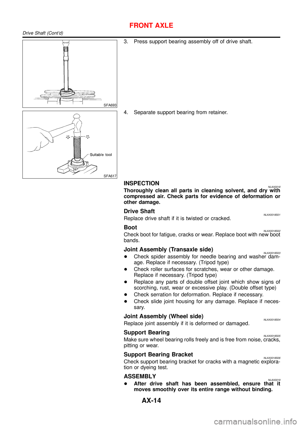
3. Press support bearing assembly off of drive shaft.
SFA617
4. Separate support bearing from retainer.
INSPECTIONNLAX0018Thoroughly clean all parts in cleaning solvent, and dry with
compressed air. Check parts for evidence of deformation or
other damage.
Drive ShaftNLAX0018S01Replace drive shaft if it is twisted or cracked.
BootNLAX0018S02Check boot for fatigue, cracks or wear. Replace boot with new boot
bands.
Joint Assembly (Transaxle side)NLAX0018S03+Check spider assembly for needle bearing and washer dam-
age. Replace if necessary. (Tripod type)
+Check roller surfaces for scratches, wear or other damage.
Replace if necessary. (Tripod type)
+Replace any parts of double offset joint which show signs of
scorching, rust, wear or excessive play. (Double offset type)
+Check serration for deformation. Replace if necessary.
+Check slide joint housing for any damage. Replace if neces-
sary.
Joint Assembly (Wheel side)NLAX0018S04Replace joint assembly if it is deformed or damaged.
Support BearingNLAX0018S05Make sure wheel bearing rolls freely and is free from noise, cracks,
pitting or wear.
Support Bearing BracketNLAX0018S06Check support bearing bracket for cracks with a magnetic explora-
tion or dyeing test.
ASSEMBLYNLAX0019+After drive shaft has been assembled, ensure that it
moves smoothly over its entire range without binding.
FRONT AXLE
Drive Shaft (Cont’d)
AX-14
Page 226 of 3051
+Use grease according to AX-19, SDS.
SFA800
Wheel Side (B83, B90 & AC2300I)NLAX0019S011. Install boot and new small boot band on drive shaft.
Cover drive shaft serration with tape so as not to damage boot
during installation.
SFA942A
2. Set joint assembly onto drive shaft by lightly tapping it.
Install joint assembly securely, ensuring marks which were
made during disassembly are properly aligned.
SFA592B
3. Pack drive shaft with specified amount of grease.
Specified amount of grease:
Refer to AX-19, SDS
4. Make sure that boot is properly installed on the drive shaft
groove.
Set boot so that it does not swell and deform when its length
is“L
1”.
Length“L
1”:
Refer to AX-19, SDS
SFA443B
5. Lock new larger and smaller boot bands securely with a suit-
able tool.
FRONT AXLE
Drive Shaft (Cont’d)
AX-15
Page 230 of 3051

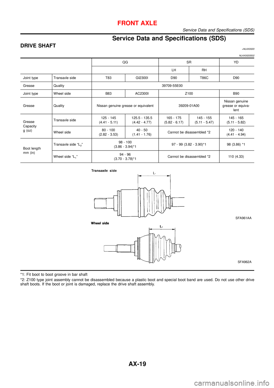
Service Data and Specifications (SDS)
DRIVE SHAFT=NLAX0020
NLAX0020S02
QG SR YD
LH RH
Joint type Transaxle side T83 GI2300I D90 T86C D90
Grease Quality 39709-55E00
Joint type Wheel side B83 AC2300I Z100 B90
Grease Quality Nissan genuine grease or equivalent 39209-01A00Nissan genuine
grease or equiva-
lent
Grease
Capacity
g (oz)Transaxle side125 - 145
(4.41 - 5.11)125.5 - 135.5
(4.42 - 4.77)165 - 175
(5.82 - 6.17)145 - 155
(5.11 - 5.47)145 - 165
(5.11 - 5.82)
Wheel side80 - 100
(2.82 - 3.53)40-50
(1.41 - 1.76)Cannot be disassembled *2120 - 140
(4.41 - 4.94)
Boot length
mm (in)Transaxle side“L
2”98 - 100
(3.86 - 3.94)*197 - 99 (3.82 - 3.90)*1 98 (3.86) *1
Wheel side“L
1”94-96
(3.70 - 3.78)*1Cannot be disassembled *2 110 (4.33)
SFA961AA
SFA962A
*1: Fit boot to boot groove in bar shaft
*2: Z100 type joint assembly cannot be disassembled because a plastic boot and special boot band are used. Do not use other drive
shaft boots. If the boot or joint is damaged, replace the drive shaft assembly.
FRONT AXLE
Service Data and Specifications (SDS)
AX-19
Page 231 of 3051
DYNAMIC DAMPER (WHERE FITTED)=NLAX0033
NLAX0033S01
Unit: mm (in)
QG YD SR
LH RH LH RH LH RH
Distance“A”178 - 184
(7.01 - 7.24)375 - 381
(14.76 - 15.00)172 - 178
(6.77 - 7.01)190 -196
(7.48 - 7.72)205 -215
(8.07 - 8.46)205 - 215
(8.07 - 8.46)
“B”70 (2.76) 64 (2.52) 70 (2.76) 70 (2.76) 70 (2.76) 70 (2.76)
SAX015
WHEEL BEARING (FRONT)NLAX0021
Wheel bearing axial end play limit mm (in) 0.05 (0.0020)
Wheel bearing lock nut tightening torque
N·m (kg-m, ft-lb)255 - 333 (26 - 34, 188 - 245)
FRONT AXLE
Service Data and Specifications (SDS) (Cont’d)
AX-20
Page 232 of 3051
SBR686C
Precautions
PRECAUTIONSNLAX0022+When installing each rubber part, final tightening must be
carried out under unladen condition* with tires on ground.
*: Fuel, radiator coolant and engine oil full. Spare tire, jack,
hand tools and mats in designated positions.
+Use flare nut wrench when removing or installing brake
tubes.
+After installing removed suspension parts, check wheel
alignment.
+Do not jack up at the trailing arm and lateral link.
+Always torque brake lines when installing.
Preparation
SPECIAL SERVICE TOOLSNLAX0032
Tool number
Tool nameDescription
KV40104710
Drift
NT474
Install ABS sensor rotor
a: 76.3 mm (3.004 in) dia.
b: 67.9 mm (2.673 in) dia.
ST3072000
Drift
NT115
Install ABS sensor rotor
a: 77 mm (3.03 in) dia.
b: 55.5 mm (2.185 in) dia.
COMMERCIAL SERVICE TOOLSNLAX0024
Tool name Description
1 Flare nut crowfoot
2 Torque wrench
NT360
Removing and installing brake piping
a: 10 mm (0.39 in)
REAR AXLE
Precautions
AX-21
Page 233 of 3051
Noise, Vibration and Harshness (NVH)
Troubleshooting
NLAX0025Refer to“Noise, Vibration and Harshness (NVH) Troubleshooting”,
“FRONT AXLE”, AX-3.
SMA525A
On-vehicle Service
REAR AXLE PARTSNLAX0026Check axle and suspension parts for excessive play, wear or dam-
age.
+Shake each rear wheel to check for excessive play.
SRA690A
REAR WHEEL BEARINGNLAX0027+Check axial end play.
Axial end play:
0.05 mm (0.0020 in)
+Check that wheel hub bearings operate smoothly.
+Check tightening torque of wheel bearing lock nut.
: 187 - 254 N·m (19 - 26 kg-m, 138 - 188 ft-lb)
+Replace wheel bearing assembly if there is axial end play or
wheel bearing does not turn smoothly. Refer to“Wheel Hub”,
“REAR AXLE”, AX-23.
REAR AXLE
Noise, Vibration and Harshness (NVH) Troubleshooting
AX-22
Page 234 of 3051
Wheel Hub
COMPONENTSNLAX0028
NAX001
1. Spindle
2. Baffle plate
3. ABS sensor rotor4. Wheel hub bearing
5. Wheel bearing lock nut6. Hub cap
7. ABS sensor
REMOVALNLAX0029CAUTION:
+Before removing the rear wheel hub assembly, disconnect
the ABS wheel sensor from the assembly. Then move it
away from the hub assembly. Failure to do so may result
in damage to the sensor wires and the sensor becoming
inoperative.
+Wheel hub bearing does not require maintenance. If any of
the following symptoms are noted, replace wheel hub
bearing assembly.
1) Growling noise is emitted from wheel hub bearing dur-
ing operation.
2) Wheel hub bearing drags or turns roughly. This occurs
when turning hub by hand after bearing lock nut is tight-
ened to specified torque.
REAR AXLE
Wheel Hub
AX-23