2001 NISSAN ALMERA TINO wheel
[x] Cancel search: wheelPage 334 of 3051
Service NoticeNLBT0001+When removing or installing various parts, place a cloth or padding onto the vehicle body to prevent
scratches.
+Handle trim, molding, instruments, grille, etc. carefully during removing or installing. Be careful not to oil
or damage them.
+Apply sealing compound where necessary when installing parts.
+When applying sealing compound, be careful that the sealing compound does not protrude from parts.
+When replacing any metal parts (for example body outer panel, members, etc.), be sure to take rust pre-
vention measures.
Supplemental Restraint System (SRS) ªAIR
BAGº and ªSEAT BELT PRE-TENSIONERº
NLBT0002The Supplemental Restraint System such as ªAIR BAGº and ªSEAT BELT PRE-TENSIONERº used along with
a seat belt, helps to reduce the risk or severity of injury to the driver and front passenger for certain types of
collision. The SRS system composition which is available to NISSAN MODEL V10 is as follows (The compo-
sition varies according to the destination and optional equipment.):
+For a frontal collision
The Supplemental Restraint System consists of driver air bag module (located in the center of the steer-
ing wheel), front passenger air bag module (located on the instrument panel on passenger side), front seat
belt pre-tensioners, a diagnosis sensor unit, warning lamp, wiring harness and spiral cable.
+For a side collision
The Supplemental Restraint System consists of front side air bag module (located in the outer side of front
seat), side air bag (satellite) sensor, diagnosis sensor unit (one of components of air bags for a frontal
collision), wiring harness, warning lamp (one of components of air bags for a frontal collision).
Information necessary to service the system safely is included in theRS sectionof this Service Manual.
WARNING:
+To avoid rendering the SRS inoperative, which could increase the risk of personal injury or death
in the event of a collision which would result in air bag inflation, all maintenance should be per-
formed by an authorized NISSAN dealer.
+Improper maintenance, including incorrect removal and installation of the SRS, can lead to per-
sonal injury caused by unintentional activation of the system. For removal of Spiral Cable and Air
Bag Module, see the RS section.
+Do not use electrical test equipment on any circuit related to the SRS unless instructed to in this
Service Manual. Spiral cable and wiring harnesses covered with yellow insulation tape either just
before the harness connectors or for the complete harness are related to the SRS.
PRECAUTIONS
Service Notice
BT-3
Page 337 of 3051
Checking Body CorrosionNLBT0033Visually check the body sheet metal panel for corrosion, paint damage (scratches, chipping, rubbing, etc.) or
damage to the anti-corrosion materials. In particular, check the following locations.
Hemmed portion
Hood front end, door lower end, trunk lid rear end, etc.
Panel joint
Side sill of rear fender and center pillar, rear wheel housing of rear fender, around strut tower in engine
compartment, etc.
Panel edge
Trunk lid opening, sunroof opening, fender wheelarch flange, fuel filler lid flange, around holes in panel, etc.
Parts contact
Waist molding, windshield molding, bumper, etc.
Protectors
Damage or condition of mudguard, fender protector, chipping protector, etc.
Anti-corrosion materials
Damage or separation of anti-corrosion materials under the body.
Drain holes
Condition of drain holes at door and side sill.
When repairing corroded areas, refer to the Corrosion Repair Manual.
CHASSIS AND BODY MAINTENANCE
Checking Body Corrosion
BT-6
Page 338 of 3051
Removal and InstallationNLBT0004+When removing or installing hood, place a cloth or other padding on hood. This prevents vehicle body from
being scratched.
+Bumper fascia is made of plastic. Do not use excessive force and be sure to keep oil away from it.
+Hood adjustment: Adjust at hinge portion.
+Hood lock adjustment: After adjusting, check hood lock control operation. Apply a coat of grease to hood
locks engaging mechanism.
+Hood opener: Do not attempt to bend cable forcibly. Doing so increases effort required to unlock hood.
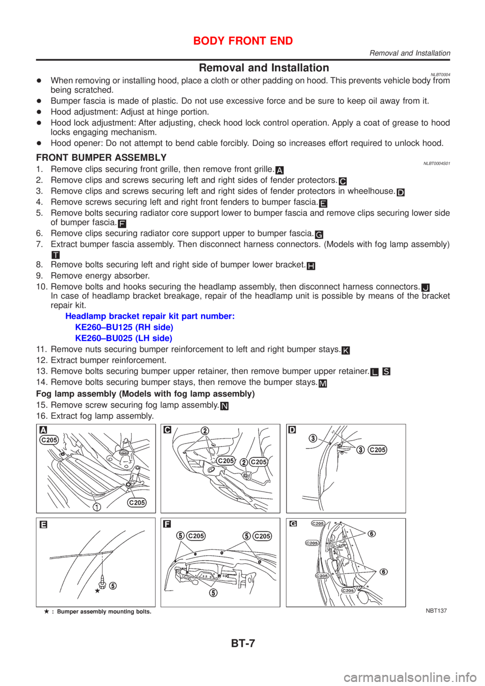
FRONT BUMPER ASSEMBLYNLBT0004S011. Remove clips securing front grille, then remove front grille.
2. Remove clips and screws securing left and right sides of fender protectors.
3. Remove clips and screws securing left and right sides of fender protectors in wheelhouse.
4. Remove screws securing left and right front fenders to bumper fascia.
5. Remove bolts securing radiator core support lower to bumper fascia and remove clips securing lower side
of bumper fascia.
6. Remove clips securing radiator core support upper to bumper fascia.
7. Extract bumper fascia assembly. Then disconnect harness connectors. (Models with fog lamp assembly)
8. Remove bolts securing left and right side of bumper lower bracket.
9. Remove energy absorber.
10. Remove bolts and hooks securing the headlamp assembly, then disconnect harness connectors.
In case of headlamp bracket breakage, repair of the headlamp unit is possible by means of the bracket
repair kit.
Headlamp bracket repair kit part number:
KE260±BU125 (RH side)
KE260±BU025 (LH side)
11. Remove nuts securing bumper reinforcement to left and right bumper stays.
12. Extract bumper reinforcement.
13. Remove bolts securing bumper upper retainer, then remove bumper upper retainer.
14. Remove bolts securing bumper stays, then remove the bumper stays.
Fog lamp assembly (Models with fog lamp assembly)
15. Remove screw securing fog lamp assembly.
16. Extract fog lamp assembly.
NBT137
BODY FRONT END
Removal and Installation
BT-7
Page 402 of 3051
CLUTCH
SECTION
CL
CONTENTS
PRECAUTIONS...............................................................2
Precautions ..................................................................2
PREPARATION...............................................................3
Special Service Tools ..................................................3
Commercial Service Tools ...........................................3
NOISE, VIBRATION AND HARSHNESS (NVH)
TROUBLESHOOTING.....................................................4
NVH Troubleshooting Chart.........................................4
CLUTCH...................................................................4
CLUTCH SYSTEM...........................................................5
Components - RHD Model with QG Engine - .............5
Components - LHD Model with QG Engine -..............6
Components - RHD Model with YD Engine -..............7
Components - LHD Model with YD Engine - ..............8
Inspection and Adjustment ..........................................9
CLUTCH PEDAL INSPECTION...................................9
CLUTCH PEDAL ADJUSTMENT...............................10
AIR BLEEDING PROCEDURE..................................10
CLUTCH MASTER CYLINDER..................................... 11
Components............................................................... 11
Removal .....................................................................12
Installation ..................................................................12
Disassembly...............................................................12
Inspection...................................................................12
Assembly ...................................................................13
OPERATING CYLINDER...............................................14
Components...............................................................14
Removal .....................................................................14
Disassembly...............................................................14
Inspection...................................................................14
Assembly ...................................................................15
Installation ..................................................................15
PIPING...........................................................................16
Removal .....................................................................16Installation ..................................................................16
RS5F70A
CLUTCH RELEASE MECHANISM...............................17
Components...............................................................17
Removal .....................................................................17
Inspection...................................................................17
Installation ..................................................................17
RS5F50A
CLUTCH RELEASE MECHANISM...............................20
Components...............................................................20
Removal .....................................................................20
Inspection...................................................................20
Installation ..................................................................20
CLUTCH DISC, CLUTCH COVER AND
FLYWHEEL....................................................................22
Components...............................................................22
Inspection and Adjustment ........................................22
CLUTCH DISC.........................................................22
CLUTCH COVER.....................................................23
FLYWHEEL.............................................................23
Installation ..................................................................23
SERVICE DATA AND SPECIFICATIONS (SDS).........24
Clutch Control System ...............................................24
Clutch Master Cylinder ..............................................24
Clutch Operating Cylinder .........................................24
Clutch Disc.................................................................24
Clutch Cover ..............................................................24
Clutch Pedal ..............................................................24
Page 405 of 3051
NLCL0004
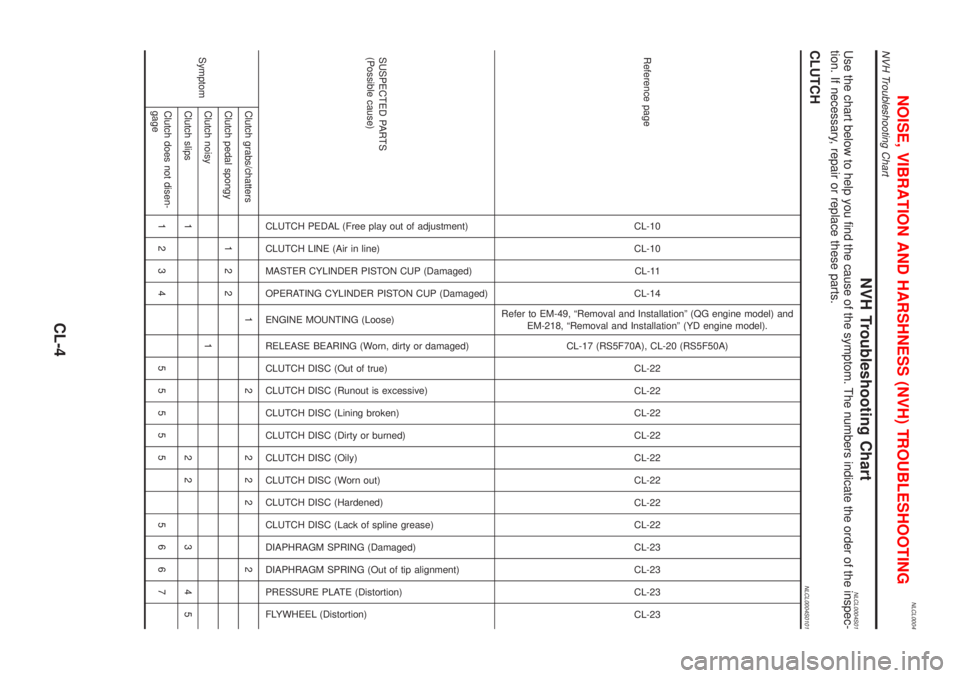
NVH Troubleshooting ChartNLCL0004S01Use the chart below to help you find the cause of the symptom. The numbers indicate the order of the inspec-
tion. If necessary, repair or replace these parts.
CLUTCHNLCL0004S0101
Reference pageCL-10
CL-10
CL-11
CL-14
Refer to EM-49, ªRemoval and Installationº (QG engine model) and
EM-218, ªRemoval and Installationº (YD engine model).
CL-17 (RS5F70A), CL-20 (RS5F50A)
CL-22
CL-22
CL-22
CL-22
CL-22
CL-22
CL-22
CL-22
CL-23
CL-23
CL-23
CL-23
SUSPECTED PARTS
(Possible cause)
CLUTCH PEDAL (Free play out of adjustment)
CLUTCH LINE (Air in line)
MASTER CYLINDER PISTON CUP (Damaged)
OPERATING CYLINDER PISTON CUP (Damaged)
ENGINE MOUNTING (Loose)
RELEASE BEARING (Worn, dirty or damaged)
CLUTCH DISC (Out of true)
CLUTCH DISC (Runout is excessive)
CLUTCH DISC (Lining broken)
CLUTCH DISC (Dirty or burned)
CLUTCH DISC (Oily)
CLUTCH DISC (Worn out)
CLUTCH DISC (Hardened)
CLUTCH DISC (Lack of spline grease)
DIAPHRAGM SPRING (Damaged)
DIAPHRAGM SPRING (Out of tip alignment)
PRESSURE PLATE (Distortion)
FLYWHEEL (Distortion)
SymptomClutch grabs/chatters 1 2 2 2 2 2
Clutch pedal spongy 1 2 2
Clutch noisy 1
Clutch slips 1 2 2 3 4 5
Clutch does not disen-
gage1234 55555 5667
NOISE, VIBRATION AND HARSHNESS (NVH) TROUBLESHOOTING
NVH Troubleshooting Chart
CL-4
Page 410 of 3051
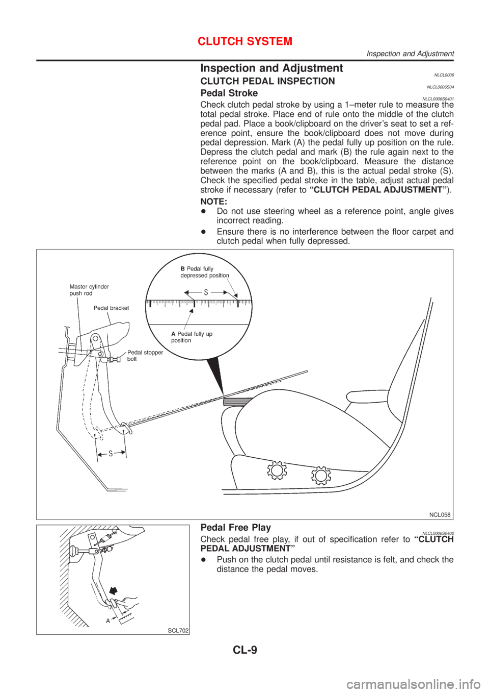
Inspection and AdjustmentNLCL0006CLUTCH PEDAL INSPECTIONNLCL0006S04Pedal StrokeNLCL0006S0401Check clutch pedal stroke by using a 1±meter rule to measure the
total pedal stroke. Place end of rule onto the middle of the clutch
pedal pad. Place a book/clipboard on the driver's seat to set a ref-
erence point, ensure the book/clipboard does not move during
pedal depression. Mark (A) the pedal fully up position on the rule.
Depress the clutch pedal and mark (B) the rule again next to the
reference point on the book/clipboard. Measure the distance
between the marks (A and B), this is the actual pedal stroke (S).
Check the specified pedal stroke in the table, adjust actual pedal
stroke if necessary (refer toªCLUTCH PEDAL ADJUSTMENTº).
NOTE:
+Do not use steering wheel as a reference point, angle gives
incorrect reading.
+Ensure there is no interference between the floor carpet and
clutch pedal when fully depressed.
NCL058
SCL702
Pedal Free PlayNLCL0006S0402Check pedal free play, if out of specification refer toªCLUTCH
PEDAL ADJUSTMENTº
+Push on the clutch pedal until resistance is felt, and check the
distance the pedal moves.
CLUTCH SYSTEM
Inspection and Adjustment
CL-9
Page 418 of 3051
ComponentsNLCL0044
SCL819
SCL820
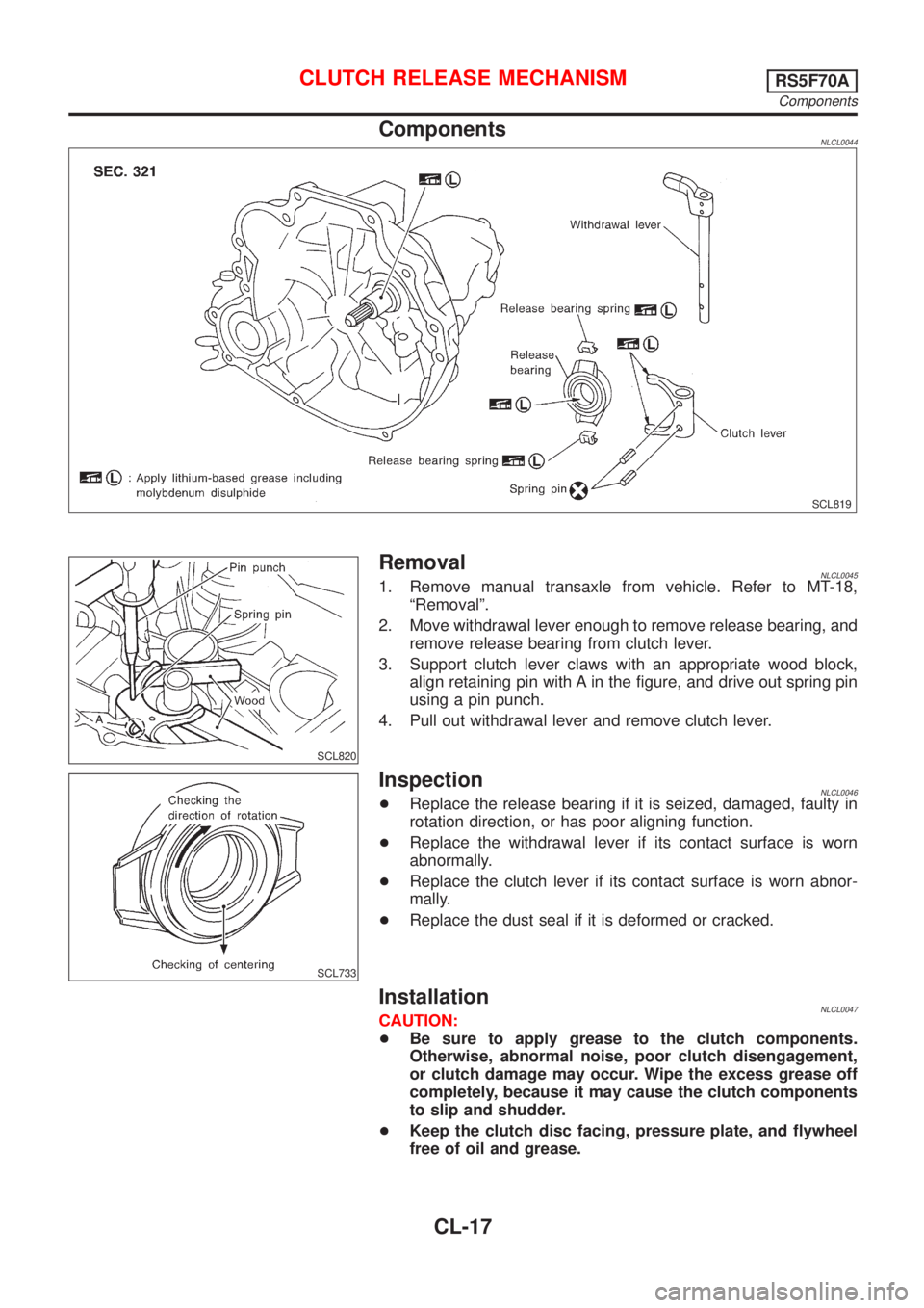
RemovalNLCL00451. Remove manual transaxle from vehicle. Refer to MT-18,
ªRemovalº.
2. Move withdrawal lever enough to remove release bearing, and
remove release bearing from clutch lever.
3. Support clutch lever claws with an appropriate wood block,
align retaining pin with A in the figure, and drive out spring pin
using a pin punch.
4. Pull out withdrawal lever and remove clutch lever.
SCL733
InspectionNLCL0046+Replace the release bearing if it is seized, damaged, faulty in
rotation direction, or has poor aligning function.
+Replace the withdrawal lever if its contact surface is worn
abnormally.
+Replace the clutch lever if its contact surface is worn abnor-
mally.
+Replace the dust seal if it is deformed or cracked.
InstallationNLCL0047CAUTION:
+Be sure to apply grease to the clutch components.
Otherwise, abnormal noise, poor clutch disengagement,
or clutch damage may occur. Wipe the excess grease off
completely, because it may cause the clutch components
to slip and shudder.
+Keep the clutch disc facing, pressure plate, and flywheel
free of oil and grease.
CLUTCH RELEASE MECHANISMRS5F70A
Components
CL-17
Page 421 of 3051
ComponentsNLCL0027
SCL842
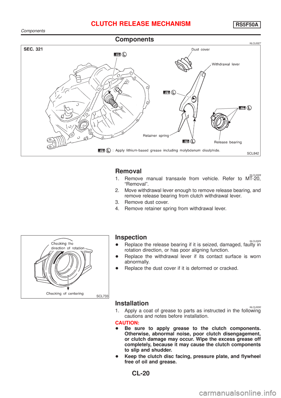
RemovalNLCL00281. Remove manual transaxle from vehicle. Refer to MT-20,
ªRemovalº.
2. Move withdrawal lever enough to remove release bearing, and
remove release bearing from clutch withdrawal lever.
3. Remove dust cover.
4. Remove retainer spring from withdrawal lever.
SCL733
InspectionNLCL0029+Replace the release bearing if it is seized, damaged, faulty in
rotation direction, or has poor aligning function.
+Replace the withdrawal lever if its contact surface is worn
abnormally.
+Replace the dust cover if it is deformed or cracked.
InstallationNLCL00301. Apply a coat of grease to parts as instructed in the following
cautions and notes before installation.
CAUTION:
+Be sure to apply grease to the clutch components.
Otherwise, abnormal noise, poor clutch disengagement,
or clutch damage may occur. Wipe the excess grease off
completely, because it may cause the clutch components
to slip and shudder.
+Keep the clutch disc facing, pressure plate, and flywheel
free of oil and grease.
CLUTCH RELEASE MECHANISMRS5F50A
Components
CL-20