2001 NISSAN ALMERA TINO exhaust manifold
[x] Cancel search: exhaust manifoldPage 257 of 3051

RemovalNLBR0123
SBR631E
1. Remove parts shown below.
+Air duct, air cleaner case (upper)
+Engine cover
+Rocker cover
+Exhaust manifold cover
+EGR tube
2. Disconnect vacuum hose from vacuum pump.
3. Remove cylinder head rear cover plate.
+Use a tool such as seal cutter (SST) to remove.
4. Loosen and remove rear cam sprocket installation bolts.
+Camshaft should not be attached. Using engine inner
resistance, loosen installation bolts.
SBR632E
5. Remove vacuum pump and cylinder head rear cover assem-
bly.
+Remove and install vacuum pump, sprocket, drive chain, and
chain guide as an assembly.
+Loosen mounting bolts in the reverse order of the numbers
shown in the figure to the left.
+Remove only bolts that are shown in the figure. (Be especially
careful not to remove M6 bolts on the vacuum pump.)
+Use a tool such as a seal cutter (SST).
VACUUM PUMP
Removal
BR-20
Page 461 of 3051
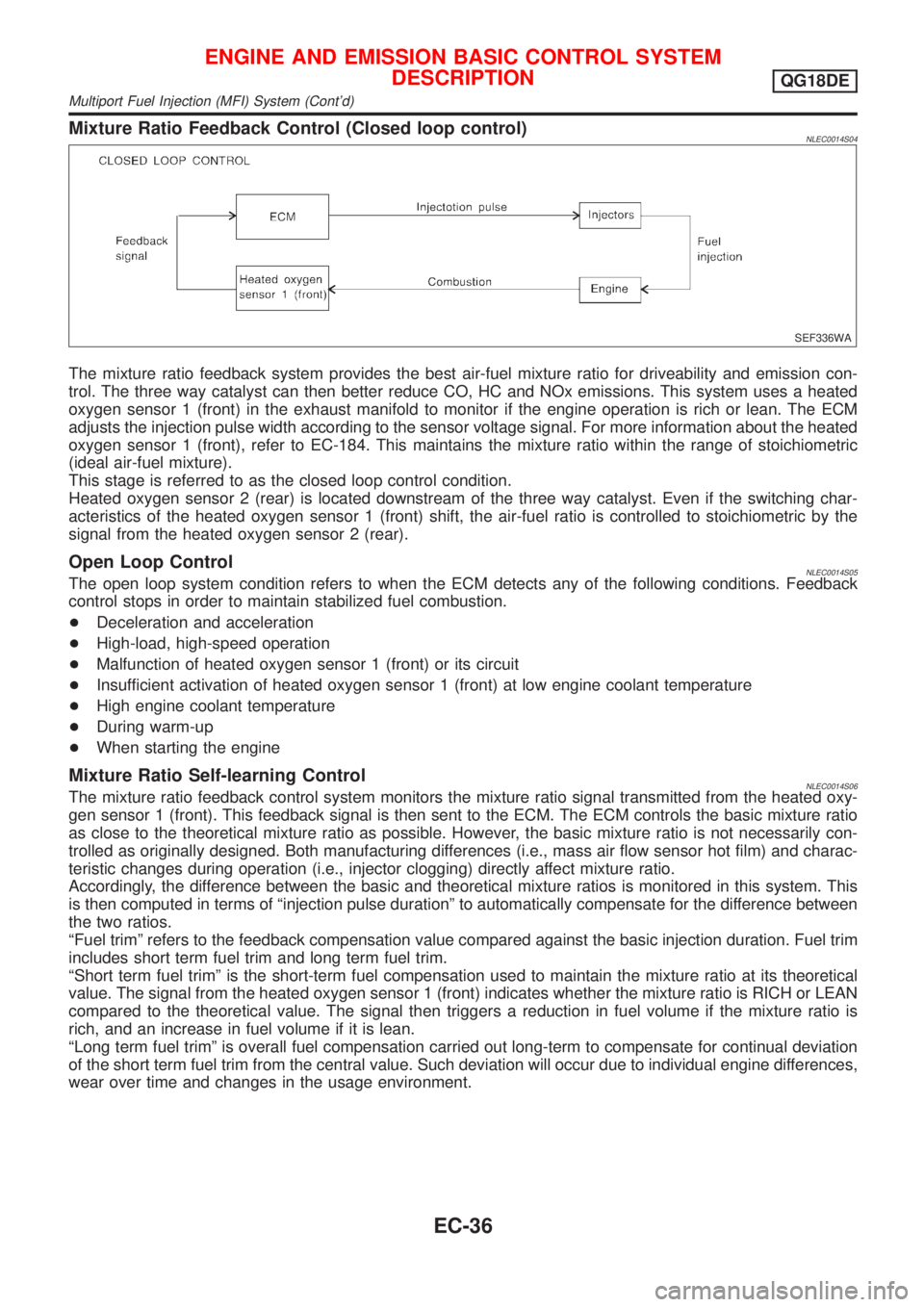
Mixture Ratio Feedback Control (Closed loop control)NLEC0014S04
SEF336WA
The mixture ratio feedback system provides the best air-fuel mixture ratio for driveability and emission con-
trol. The three way catalyst can then better reduce CO, HC and NOx emissions. This system uses a heated
oxygen sensor 1 (front) in the exhaust manifold to monitor if the engine operation is rich or lean. The ECM
adjusts the injection pulse width according to the sensor voltage signal. For more information about the heated
oxygen sensor 1 (front), refer to EC-184. This maintains the mixture ratio within the range of stoichiometric
(ideal air-fuel mixture).
This stage is referred to as the closed loop control condition.
Heated oxygen sensor 2 (rear) is located downstream of the three way catalyst. Even if the switching char-
acteristics of the heated oxygen sensor 1 (front) shift, the air-fuel ratio is controlled to stoichiometric by the
signal from the heated oxygen sensor 2 (rear).
Open Loop ControlNLEC0014S05The open loop system condition refers to when the ECM detects any of the following conditions. Feedback
control stops in order to maintain stabilized fuel combustion.
+Deceleration and acceleration
+High-load, high-speed operation
+Malfunction of heated oxygen sensor 1 (front) or its circuit
+Insufficient activation of heated oxygen sensor 1 (front) at low engine coolant temperature
+High engine coolant temperature
+During warm-up
+When starting the engine
Mixture Ratio Self-learning ControlNLEC0014S06The mixture ratio feedback control system monitors the mixture ratio signal transmitted from the heated oxy-
gen sensor 1 (front). This feedback signal is then sent to the ECM. The ECM controls the basic mixture ratio
as close to the theoretical mixture ratio as possible. However, the basic mixture ratio is not necessarily con-
trolled as originally designed. Both manufacturing differences (i.e., mass air flow sensor hot film) and charac-
teristic changes during operation (i.e., injector clogging) directly affect mixture ratio.
Accordingly, the difference between the basic and theoretical mixture ratios is monitored in this system. This
is then computed in terms of ªinjection pulse durationº to automatically compensate for the difference between
the two ratios.
ªFuel trimº refers to the feedback compensation value compared against the basic injection duration. Fuel trim
includes short term fuel trim and long term fuel trim.
ªShort term fuel trimº is the short-term fuel compensation used to maintain the mixture ratio at its theoretical
value. The signal from the heated oxygen sensor 1 (front) indicates whether the mixture ratio is RICH or LEAN
compared to the theoretical value. The signal then triggers a reduction in fuel volume if the mixture ratio is
rich, and an increase in fuel volume if it is lean.
ªLong term fuel trimº is overall fuel compensation carried out long-term to compensate for continual deviation
of the short term fuel trim from the central value. Such deviation will occur due to individual engine differences,
wear over time and changes in the usage environment.
ENGINE AND EMISSION BASIC CONTROL SYSTEM
DESCRIPTION
QG18DE
Multiport Fuel Injection (MFI) System (Cont'd)
EC-36
Page 552 of 3051
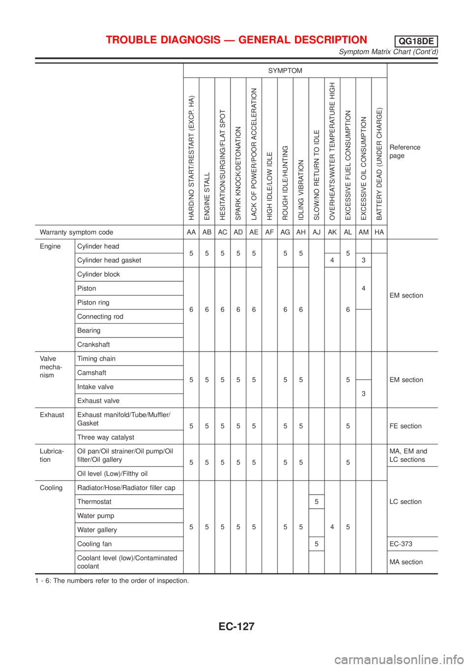
SYMPTOM
Reference
page
HARD/NO START/RESTART (EXCP. HA)
ENGINE STALL
HESITATION/SURGING/FLAT SPOT
SPARK KNOCK/DETONATION
LACK OF POWER/POOR ACCELERATION
HIGH IDLE/LOW IDLE
ROUGH IDLE/HUNTING
IDLING VIBRATION
SLOW/NO RETURN TO IDLE
OVERHEATS/WATER TEMPERATURE HIGH
EXCESSIVE FUEL CONSUMPTION
EXCESSIVE OIL CONSUMPTION
BATTERY DEAD (UNDER CHARGE)
Warranty symptom code AA AB AC AD AE AF AG AH AJ AK AL AM HA
Engine Cylinder head
55555 55 5
EM section Cylinder head gasket 4 3
Cylinder block
66666 66 64 Piston
Piston ring
Connecting rod
Bearing
Crankshaft
Valve
mecha-
nismTiming chain
55555 55 5 EMsection Camshaft
Intake valve
3
Exhaust valve
Exhaust Exhaust manifold/Tube/Muffler/
Gasket
55555 55 5 FEsection
Three way catalyst
Lubrica-
tionOil pan/Oil strainer/Oil pump/Oil
filter/Oil gallery
55555 55 5MA, EM and
LC sections
Oil level (Low)/Filthy oil
LC section Cooling Radiator/Hose/Radiator filler cap
55555 55 45 Thermostat 5
Water pump
Water gallery
Cooling fan 5 EC-373
Coolant level (low)/Contaminated
coolantMA section
1 - 6: The numbers refer to the order of inspection.
TROUBLE DIAGNOSIS Ð GENERAL DESCRIPTIONQG18DE
Symptom Matrix Chart (Cont'd)
EC-127
Page 609 of 3051
SEF463R
SEF288D
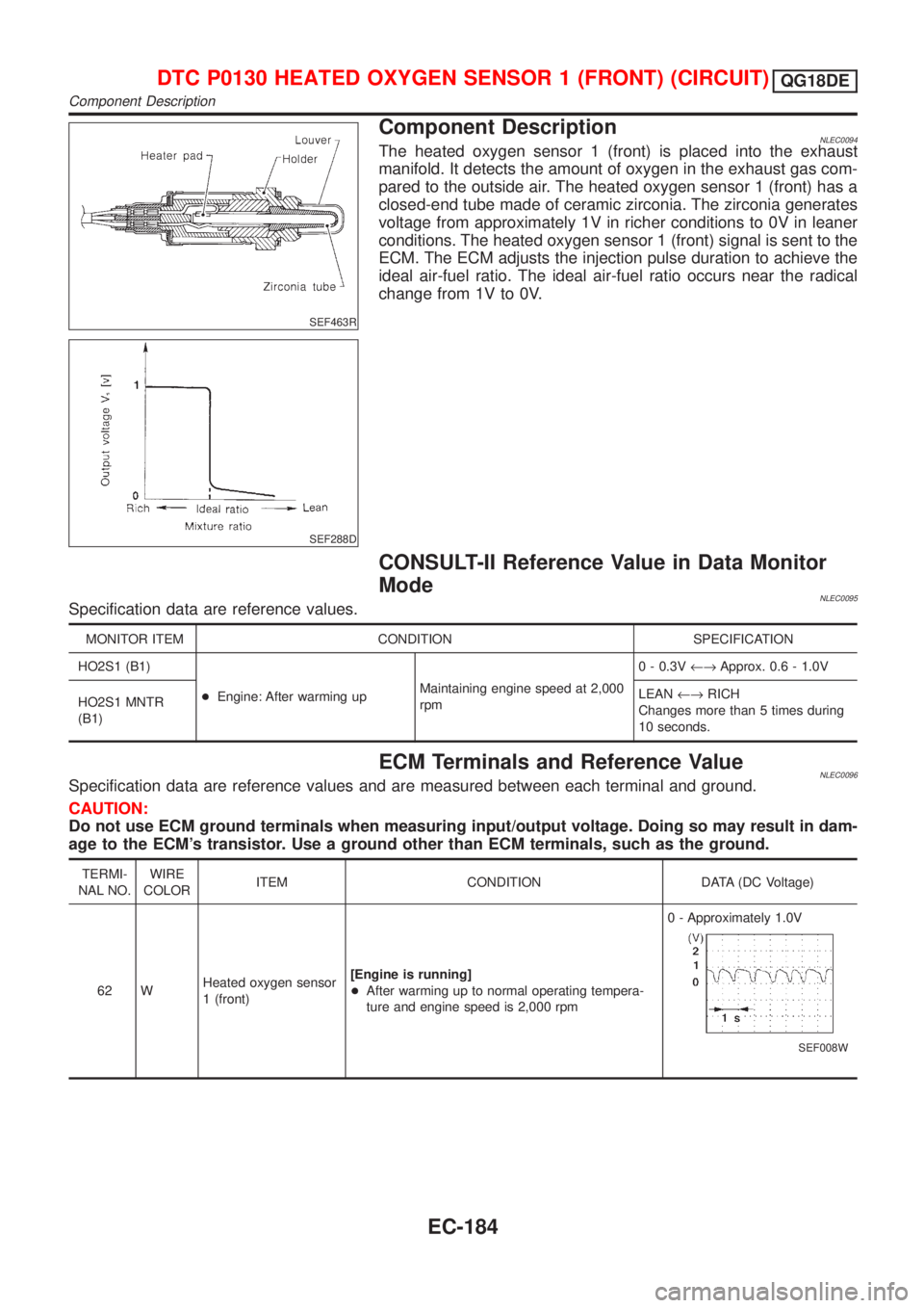
Component DescriptionNLEC0094The heated oxygen sensor 1 (front) is placed into the exhaust
manifold. It detects the amount of oxygen in the exhaust gas com-
pared to the outside air. The heated oxygen sensor 1 (front) has a
closed-end tube made of ceramic zirconia. The zirconia generates
voltage from approximately 1V in richer conditions to 0V in leaner
conditions. The heated oxygen sensor 1 (front) signal is sent to the
ECM. The ECM adjusts the injection pulse duration to achieve the
ideal air-fuel ratio. The ideal air-fuel ratio occurs near the radical
change from 1V to 0V.
CONSULT-II Reference Value in Data Monitor
Mode
NLEC0095Specification data are reference values.
MONITOR ITEM CONDITION SPECIFICATION
HO2S1 (B1)
+Engine: After warming upMaintaining engine speed at 2,000
rpm0 - 0.3V¨Approx. 0.6 - 1.0V
HO2S1 MNTR
(B1)LEAN¨RICH
Changes more than 5 times during
10 seconds.
ECM Terminals and Reference ValueNLEC0096Specification data are reference values and are measured between each terminal and ground.
CAUTION:
Do not use ECM ground terminals when measuring input/output voltage. Doing so may result in dam-
age to the ECM's transistor. Use a ground other than ECM terminals, such as the ground.
TERMI-
NAL NO.WIRE
COLORITEM CONDITION DATA (DC Voltage)
62 WHeated oxygen sensor
1 (front)[Engine is running]
+After warming up to normal operating tempera-
ture and engine speed is 2,000 rpm0 - Approximately 1.0V
SEF008W
DTC P0130 HEATED OXYGEN SENSOR 1 (FRONT) (CIRCUIT)QG18DE
Component Description
EC-184
Page 617 of 3051
SEF463R
SEF288D
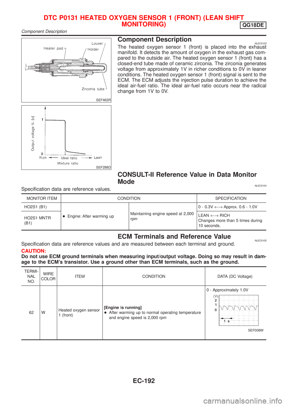
Component DescriptionNLEC0103The heated oxygen sensor 1 (front) is placed into the exhaust
manifold. It detects the amount of oxygen in the exhaust gas com-
pared to the outside air. The heated oxygen sensor 1 (front) has a
closed-end tube made of ceramic zirconia. The zirconia generates
voltage from approximately 1V in richer conditions to 0V in leaner
conditions. The heated oxygen sensor 1 (front) signal is sent to the
ECM. The ECM adjusts the injection pulse duration to achieve the
ideal air-fuel ratio. The ideal air-fuel ratio occurs near the radical
change from 1V to 0V.
CONSULT-II Reference Value in Data Monitor
Mode
NLEC0104Specification data are reference values.
MONITOR ITEM CONDITION SPECIFICATION
HO2S1 (B1)
+Engine: After warming upMaintaining engine speed at 2,000
rpm0 - 0.3V¨Approx. 0.6 - 1.0V
HO2S1 MNTR
(B1)LEAN¨RICH
Changes more than 5 times during
10 seconds.
ECM Terminals and Reference ValueNLEC0105Specification data are reference values and are measured between each terminal and ground.
CAUTION:
Do not use ECM ground terminals when measuring input/output voltage. Doing so may result in dam-
age to the ECM's transistor. Use a ground other than ECM terminals, such as the ground.
TERMI-
NAL
NO.WIRE
COLORITEM CONDITION DATA (DC Voltage)
62 WHeated oxygen sensor
1 (front)[Engine is running]
+After warming up to normal operating temperature
and engine speed is 2,000 rpm0 - Approximately 1.0V
SEF008W
DTC P0131 HEATED OXYGEN SENSOR 1 (FRONT) (LEAN SHIFT
MONITORING)
QG18DE
Component Description
EC-192
Page 623 of 3051
SEF463R
SEF288D
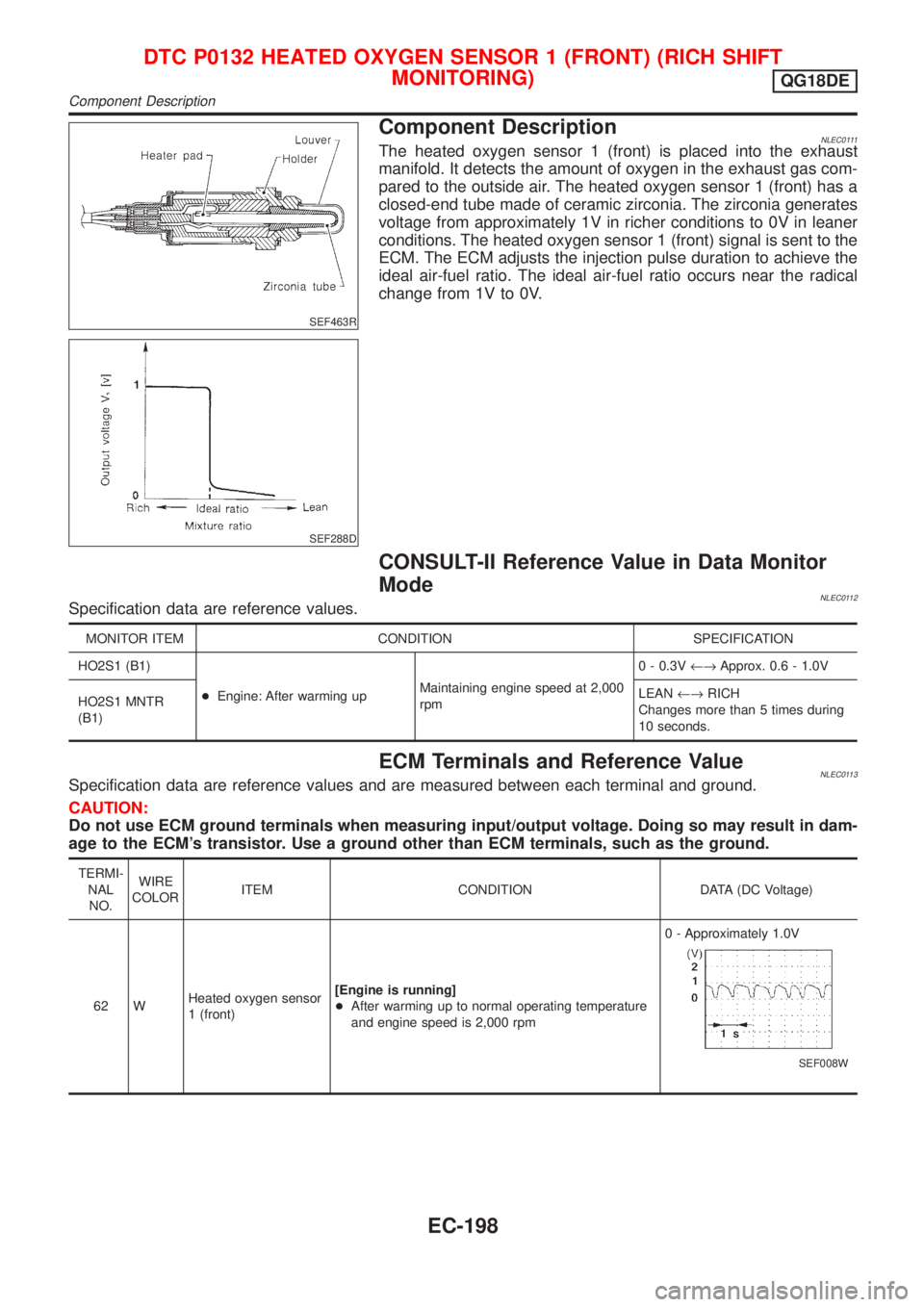
Component DescriptionNLEC0111The heated oxygen sensor 1 (front) is placed into the exhaust
manifold. It detects the amount of oxygen in the exhaust gas com-
pared to the outside air. The heated oxygen sensor 1 (front) has a
closed-end tube made of ceramic zirconia. The zirconia generates
voltage from approximately 1V in richer conditions to 0V in leaner
conditions. The heated oxygen sensor 1 (front) signal is sent to the
ECM. The ECM adjusts the injection pulse duration to achieve the
ideal air-fuel ratio. The ideal air-fuel ratio occurs near the radical
change from 1V to 0V.
CONSULT-II Reference Value in Data Monitor
Mode
NLEC0112Specification data are reference values.
MONITOR ITEM CONDITION SPECIFICATION
HO2S1 (B1)
+Engine: After warming upMaintaining engine speed at 2,000
rpm0 - 0.3V¨Approx. 0.6 - 1.0V
HO2S1 MNTR
(B1)LEAN¨RICH
Changes more than 5 times during
10 seconds.
ECM Terminals and Reference ValueNLEC0113Specification data are reference values and are measured between each terminal and ground.
CAUTION:
Do not use ECM ground terminals when measuring input/output voltage. Doing so may result in dam-
age to the ECM's transistor. Use a ground other than ECM terminals, such as the ground.
TERMI-
NAL
NO.WIRE
COLORITEM CONDITION DATA (DC Voltage)
62 WHeated oxygen sensor
1 (front)[Engine is running]
+After warming up to normal operating temperature
and engine speed is 2,000 rpm0 - Approximately 1.0V
SEF008W
DTC P0132 HEATED OXYGEN SENSOR 1 (FRONT) (RICH SHIFT
MONITORING)
QG18DE
Component Description
EC-198
Page 629 of 3051
SEF463R
SEF288D
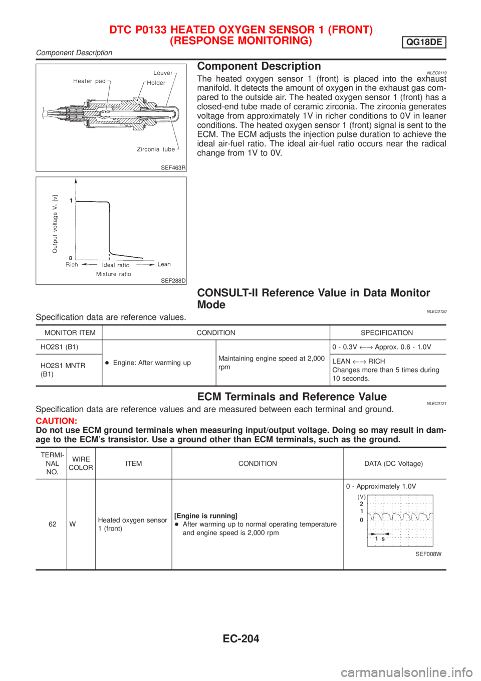
Component DescriptionNLEC0119The heated oxygen sensor 1 (front) is placed into the exhaust
manifold. It detects the amount of oxygen in the exhaust gas com-
pared to the outside air. The heated oxygen sensor 1 (front) has a
closed-end tube made of ceramic zirconia. The zirconia generates
voltage from approximately 1V in richer conditions to 0V in leaner
conditions. The heated oxygen sensor 1 (front) signal is sent to the
ECM. The ECM adjusts the injection pulse duration to achieve the
ideal air-fuel ratio. The ideal air-fuel ratio occurs near the radical
change from 1V to 0V.
CONSULT-II Reference Value in Data Monitor
Mode
NLEC0120Specification data are reference values.
MONITOR ITEM CONDITION SPECIFICATION
HO2S1 (B1)
+Engine: After warming upMaintaining engine speed at 2,000
rpm0 - 0.3V¨Approx. 0.6 - 1.0V
HO2S1 MNTR
(B1)LEAN¨RICH
Changes more than 5 times during
10 seconds.
ECM Terminals and Reference ValueNLEC0121Specification data are reference values and are measured between each terminal and ground.
CAUTION:
Do not use ECM ground terminals when measuring input/output voltage. Doing so may result in dam-
age to the ECM's transistor. Use a ground other than ECM terminals, such as the ground.
TERMI-
NAL
NO.WIRE
COLORITEM CONDITION DATA (DC Voltage)
62 WHeated oxygen sensor
1 (front)[Engine is running]
+After warming up to normal operating temperature
and engine speed is 2,000 rpm0 - Approximately 1.0V
SEF008W
DTC P0133 HEATED OXYGEN SENSOR 1 (FRONT)
(RESPONSE MONITORING)
QG18DE
Component Description
EC-204
Page 639 of 3051
SEF463R
SEF288D
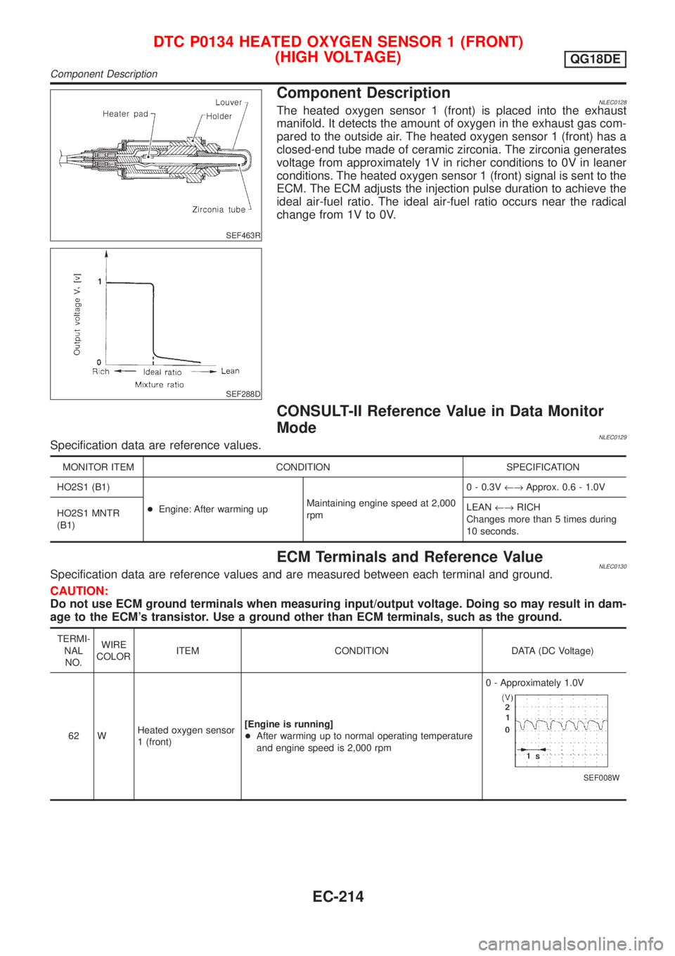
Component DescriptionNLEC0128The heated oxygen sensor 1 (front) is placed into the exhaust
manifold. It detects the amount of oxygen in the exhaust gas com-
pared to the outside air. The heated oxygen sensor 1 (front) has a
closed-end tube made of ceramic zirconia. The zirconia generates
voltage from approximately 1V in richer conditions to 0V in leaner
conditions. The heated oxygen sensor 1 (front) signal is sent to the
ECM. The ECM adjusts the injection pulse duration to achieve the
ideal air-fuel ratio. The ideal air-fuel ratio occurs near the radical
change from 1V to 0V.
CONSULT-II Reference Value in Data Monitor
Mode
NLEC0129Specification data are reference values.
MONITOR ITEM CONDITION SPECIFICATION
HO2S1 (B1)
+Engine: After warming upMaintaining engine speed at 2,000
rpm0 - 0.3V¨Approx. 0.6 - 1.0V
HO2S1 MNTR
(B1)LEAN¨RICH
Changes more than 5 times during
10 seconds.
ECM Terminals and Reference ValueNLEC0130Specification data are reference values and are measured between each terminal and ground.
CAUTION:
Do not use ECM ground terminals when measuring input/output voltage. Doing so may result in dam-
age to the ECM's transistor. Use a ground other than ECM terminals, such as the ground.
TERMI-
NAL
NO.WIRE
COLORITEM CONDITION DATA (DC Voltage)
62 WHeated oxygen sensor
1 (front)[Engine is running]
+After warming up to normal operating temperature
and engine speed is 2,000 rpm0 - Approximately 1.0V
SEF008W
DTC P0134 HEATED OXYGEN SENSOR 1 (FRONT)
(HIGH VOLTAGE)
QG18DE
Component Description
EC-214