Page 213 of 3051
SBR686C
Precautions
PRECAUTIONSNLAX0001+When installing rubber parts, final tightening must be car-
ried out under unladen condition* with tires on ground.
*: Fuel, radiator coolant and engine oil full. Spare tire, jack,
hand tools and mats in designated positions.
+After installing removed suspension parts, check wheel
alignment and adjust if necessary.
+Use flare nut wrench when removing or installing brake
tubes.
+Always torque brake lines when installing.
Preparation
SPECIAL SERVICE TOOLSNLAX0002
Tool number
Tool nameDescription
HT72520000
Ball joint remover
NT146
Removing tie-rod outer end and lower ball joint
KV38106800
Differential side oil seal
protector
NT147
Installing drive shaft
KV38106800
COMMERCIAL SERVICE TOOLSNLAX0003
Tool name Description
1 Flare nut crowfoot
2 Torque wrench
NT360
Removing and installing each brake piping
a: 10 mm (0.39 in)
FRONT AXLE
Precautions
AX-2
Page 214 of 3051
Noise, Vibration and Harshness (NVH)
Troubleshooting
=NLAX0004NVH TROUBLESHOOTING CHARTNLAX0004S01Use the chart below to help you find the cause of the symptom. If necessary, repair or replace these parts.
Reference page—
AX-14
—
AX-5, 23
—
AX-3, 22
—
—
SU-4
SU-4
SU-4
BR-6
ST-5
Possible cause and
SUSPECTED PARTS
Excessive joint angle
Joint sliding resistance
Imbalance
Improper installation, looseness
Parts interference
Wheel bearing damage
DRIVE SHAFT
AXLE
SUSPENSION
TIRES
ROAD WHEEL
BRAKES
STEERING
SymptomDRIVE SHAFTNoise, Vibration× × × ×××× ×
Shake× × × ×××× ×
AXLENoise×× × ×××× ×
Shake×× × ×××× ×
Vibration×× × ×× ×
Shimmy×× ×××× ×
Judder× ×××× ×
Poor quality ride or
handling××× ×××
×: Applicable
SMA525A
On-vehicle Service
FRONT AXLE PARTSNLAX0005Check front axle and front suspension parts for excessive play,
cracks, wear or other damage.
+Shake each front wheel to check for excessive play.
+Make sure that cotter pin is inserted.
+Retighten all axle and suspension nuts and bolts to the speci-
fied torque.
Tightening torque:
Refer to SU-4, “FRONT SUSPENSION”.
SFA805B
FRONT WHEEL BEARINGNLAX0006+Check that wheel bearings operate smoothly.
+Check axial end play.
Axial end play:
0.05 mm (0.0020 in)
If out of specification or wheel bearing does not turn smoothly,
replace wheel bearing assembly.
Refer to “Wheel Hub and Knuckle”, “FRONT AXLE”, AX-5.
FRONT AXLE
Noise, Vibration and Harshness (NVH) Troubleshooting
AX-3
Page 231 of 3051
DYNAMIC DAMPER (WHERE FITTED)=NLAX0033
NLAX0033S01
Unit: mm (in)
QG YD SR
LH RH LH RH LH RH
Distance“A”178 - 184
(7.01 - 7.24)375 - 381
(14.76 - 15.00)172 - 178
(6.77 - 7.01)190 -196
(7.48 - 7.72)205 -215
(8.07 - 8.46)205 - 215
(8.07 - 8.46)
“B”70 (2.76) 64 (2.52) 70 (2.76) 70 (2.76) 70 (2.76) 70 (2.76)
SAX015
WHEEL BEARING (FRONT)NLAX0021
Wheel bearing axial end play limit mm (in) 0.05 (0.0020)
Wheel bearing lock nut tightening torque
N·m (kg-m, ft-lb)255 - 333 (26 - 34, 188 - 245)
FRONT AXLE
Service Data and Specifications (SDS) (Cont’d)
AX-20
Page 232 of 3051
SBR686C
Precautions
PRECAUTIONSNLAX0022+When installing each rubber part, final tightening must be
carried out under unladen condition* with tires on ground.
*: Fuel, radiator coolant and engine oil full. Spare tire, jack,
hand tools and mats in designated positions.
+Use flare nut wrench when removing or installing brake
tubes.
+After installing removed suspension parts, check wheel
alignment.
+Do not jack up at the trailing arm and lateral link.
+Always torque brake lines when installing.
Preparation
SPECIAL SERVICE TOOLSNLAX0032
Tool number
Tool nameDescription
KV40104710
Drift
NT474
Install ABS sensor rotor
a: 76.3 mm (3.004 in) dia.
b: 67.9 mm (2.673 in) dia.
ST3072000
Drift
NT115
Install ABS sensor rotor
a: 77 mm (3.03 in) dia.
b: 55.5 mm (2.185 in) dia.
COMMERCIAL SERVICE TOOLSNLAX0024
Tool name Description
1 Flare nut crowfoot
2 Torque wrench
NT360
Removing and installing brake piping
a: 10 mm (0.39 in)
REAR AXLE
Precautions
AX-21
Page 233 of 3051
Noise, Vibration and Harshness (NVH)
Troubleshooting
NLAX0025Refer to“Noise, Vibration and Harshness (NVH) Troubleshooting”,
“FRONT AXLE”, AX-3.
SMA525A
On-vehicle Service
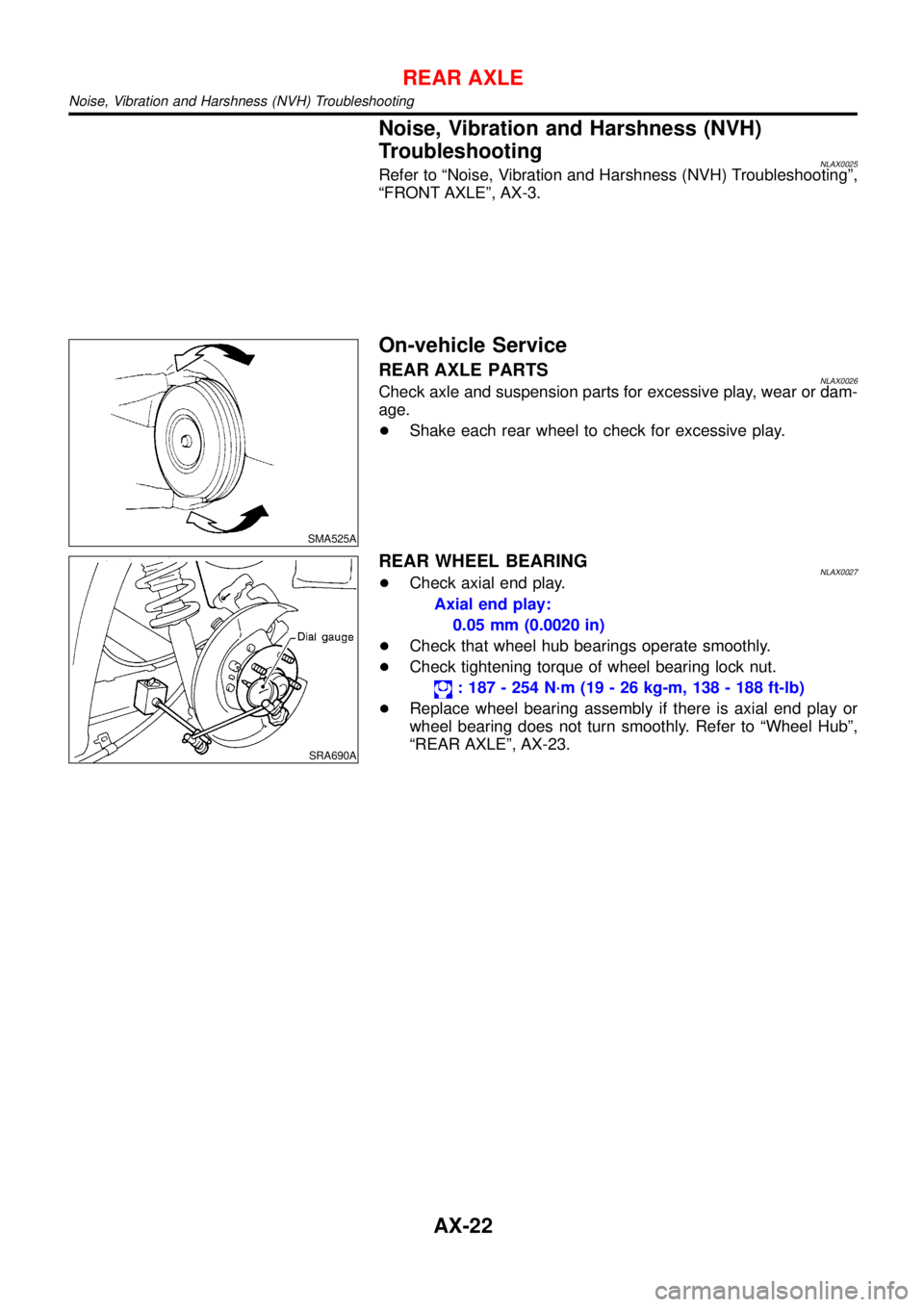
REAR AXLE PARTSNLAX0026Check axle and suspension parts for excessive play, wear or dam-
age.
+Shake each rear wheel to check for excessive play.
SRA690A
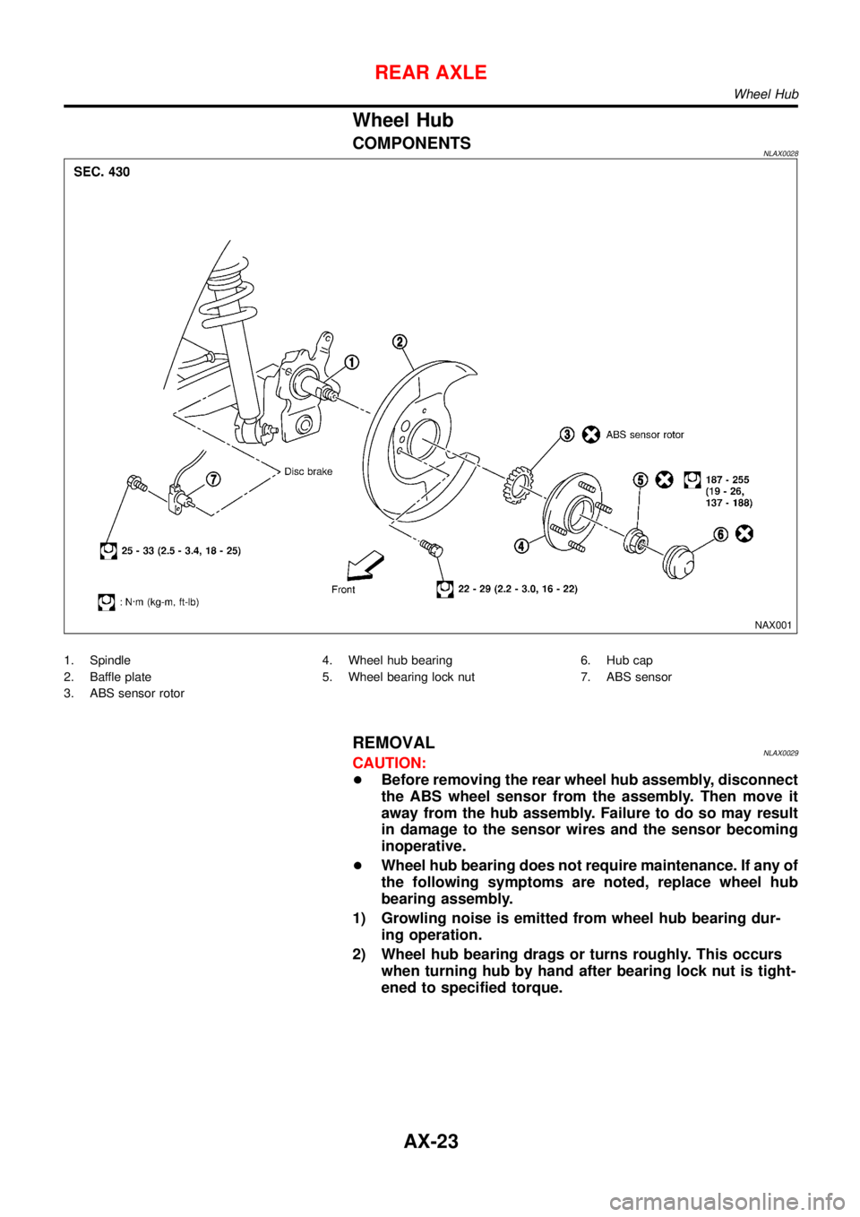
REAR WHEEL BEARINGNLAX0027+Check axial end play.
Axial end play:
0.05 mm (0.0020 in)
+Check that wheel hub bearings operate smoothly.
+Check tightening torque of wheel bearing lock nut.
: 187 - 254 N·m (19 - 26 kg-m, 138 - 188 ft-lb)
+Replace wheel bearing assembly if there is axial end play or
wheel bearing does not turn smoothly. Refer to“Wheel Hub”,
“REAR AXLE”, AX-23.
REAR AXLE
Noise, Vibration and Harshness (NVH) Troubleshooting
AX-22
Page 234 of 3051
Wheel Hub
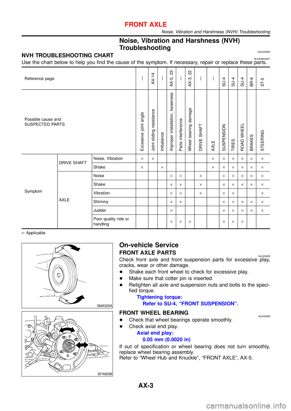
COMPONENTSNLAX0028
NAX001
1. Spindle
2. Baffle plate
3. ABS sensor rotor4. Wheel hub bearing
5. Wheel bearing lock nut6. Hub cap
7. ABS sensor
REMOVALNLAX0029CAUTION:
+Before removing the rear wheel hub assembly, disconnect
the ABS wheel sensor from the assembly. Then move it
away from the hub assembly. Failure to do so may result
in damage to the sensor wires and the sensor becoming
inoperative.
+Wheel hub bearing does not require maintenance. If any of
the following symptoms are noted, replace wheel hub
bearing assembly.
1) Growling noise is emitted from wheel hub bearing dur-
ing operation.
2) Wheel hub bearing drags or turns roughly. This occurs
when turning hub by hand after bearing lock nut is tight-
ened to specified torque.
REAR AXLE
Wheel Hub
AX-23
Page 237 of 3051
Service Data and Specifications (SDS)
WHEEL BEARING (REAR)=NLAX0031
Wheel bearing axial end play mm (in) 0.05 (0.0020)
Wheel bearing lock nut tightening torque N·m (kg-m, ft-lb) 187 - 254 (19 - 26, 138 - 188)
REAR AXLE
Service Data and Specifications (SDS)
AX-26
Page 240 of 3051
Supplemental Restraint System (SRS)“AIR
BAG”and“SEAT BELT PRE-TENSIONER”
NLBR0081The Supplemental Restraint System such as “AIR BAG” and “SEAT BELT PRE-TENSIONER” used along with
a seat belt, helps to reduce the risk or severity of injury to the driver and front passenger for certain types of
collision. The SRS system composition which is available to NISSAN MODEL V10 is as follows (The compo-
sition varies according to the destination and optional equipment.):
+For a frontal collision
The Supplemental Restraint System consists of driver air bag module (located in the center of the steer-
ing wheel), front passenger air bag module (located on the instrument panel on passenger side), front seat
belt pre-tensioners, a diagnosis sensor unit, warning lamp, wiring harness and spiral cable.
+For a side collision
The Supplemental Restraint System consists of front side air bag module (located in the outer side of front
seat), side air bag (satellite) sensor, diagnosis sensor unit (one of components of air bags for a frontal
collision), wiring harness, warning lamp (one of components of air bags for a frontal collision).
Information necessary to service the system safely is included in theRS sectionof this Service Manual.
WARNING:
+To avoid rendering the SRS inoperative, which could increase the risk of personal injury or death
in the event of a collision which would result in air bag inflation, all maintenance should be per-
formed by an authorized NISSAN dealer.
+Improper maintenance, including incorrect removal and installation of the SRS, can lead to per-
sonal injury caused by unintentional activation of the system. For removal of Spiral Cable and Air
Bag Module, see the RS section.
+Do not use electrical test equipment on any circuit related to the SRS unless instructed to in this
Service Manual. Spiral cable and wiring harnesses covered with yellow insulation tape either just
before the harness connectors or for the complete harness are related to the SRS.
SBR686C
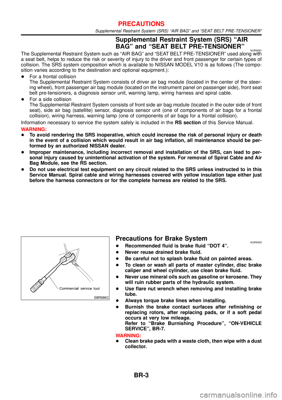
Precautions for Brake SystemNLBR0002+Recommended fluid is brake fluid“DOT 4”.
+Never reuse drained brake fluid.
+Be careful not to splash brake fluid on painted areas.
+To clean or wash all parts of master cylinder, disc brake
caliper and wheel cylinder, use clean brake fluid.
+Never use mineral oils such as gasoline or kerosene. They
will ruin rubber parts of the hydraulic system.
+Use flare nut wrench when removing and installing brake
tube.
+Always torque brake lines when installing.
+Burnish the brake contact surfaces after refinishing or
replacing rotors, after replacing pads, or if a soft pedal
occurs at very low mileage.
Refer to“Brake Burnishing Procedure”,“ON-VEHICLE
SERVICE”, BR-7.
WARNING:
+Clean brake pads with a waste cloth, then wipe with a dust
collector.
PRECAUTIONS
Supplemental Restraint System (SRS) “AIR BAG” and “SEAT BELT PRE-TENSIONER”
BR-3