Page 214 of 3051

Noise, Vibration and Harshness (NVH)
Troubleshooting
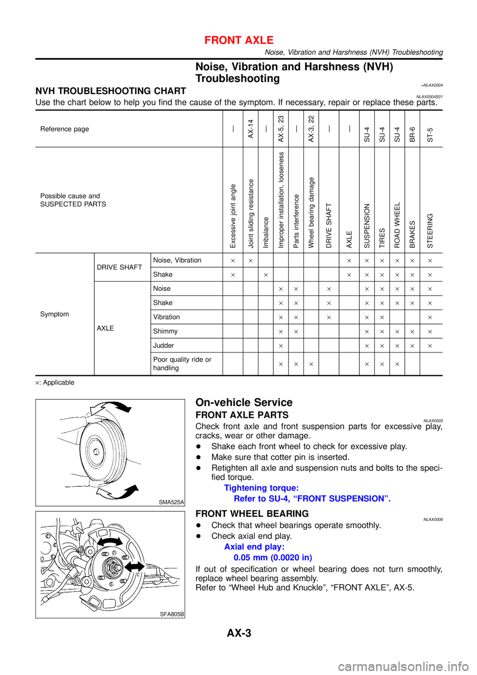
=NLAX0004NVH TROUBLESHOOTING CHARTNLAX0004S01Use the chart below to help you find the cause of the symptom. If necessary, repair or replace these parts.
Reference page—
AX-14
—
AX-5, 23
—
AX-3, 22
—
—
SU-4
SU-4
SU-4
BR-6
ST-5
Possible cause and
SUSPECTED PARTS
Excessive joint angle
Joint sliding resistance
Imbalance
Improper installation, looseness
Parts interference
Wheel bearing damage
DRIVE SHAFT
AXLE
SUSPENSION
TIRES
ROAD WHEEL
BRAKES
STEERING
SymptomDRIVE SHAFTNoise, Vibration× × × ×××× ×
Shake× × × ×××× ×
AXLENoise×× × ×××× ×
Shake×× × ×××× ×
Vibration×× × ×× ×
Shimmy×× ×××× ×
Judder× ×××× ×
Poor quality ride or
handling××× ×××
×: Applicable
SMA525A
On-vehicle Service
FRONT AXLE PARTSNLAX0005Check front axle and front suspension parts for excessive play,
cracks, wear or other damage.
+Shake each front wheel to check for excessive play.
+Make sure that cotter pin is inserted.
+Retighten all axle and suspension nuts and bolts to the speci-
fied torque.
Tightening torque:
Refer to SU-4, “FRONT SUSPENSION”.
SFA805B
FRONT WHEEL BEARINGNLAX0006+Check that wheel bearings operate smoothly.
+Check axial end play.
Axial end play:
0.05 mm (0.0020 in)
If out of specification or wheel bearing does not turn smoothly,
replace wheel bearing assembly.
Refer to “Wheel Hub and Knuckle”, “FRONT AXLE”, AX-5.
FRONT AXLE
Noise, Vibration and Harshness (NVH) Troubleshooting
AX-3
Page 216 of 3051
Wheel Hub and Knuckle
COMPONENTS=NLAX0008
NAX006
1. Drive shaft
2. Knuckle
3. Baffle plate (where fitted)
4. ABS sensor5. Wheel bearing assembly
6. Snap ring
7. Hub bolt
8. Wheel hub9. Wheel bearing lock nut
10. Cotter pin
11. Brake disc
12. Wheel nut
REMOVALNLAX0009CAUTION:
Before removing the front axle assembly, disconnect the ABS
wheel sensor from the assembly. Then move it away from the
front axle assembly area.
Failure to do so may result in damage to the sensor wires and
the sensor becoming inoperative.
SFA090A
1. Remove wheel bearing lock nut.
FRONT AXLE
Wheel Hub and Knuckle
AX-5
Page 217 of 3051
SFA898A
2. Remove brake caliper assembly and rotor.
Brake hose need not be disconnected from brake caliper. In
this case, suspend caliper assembly with wire so as not to
stretch brake hose. Be careful not to depress brake pedal, or
piston will pop out.
Make sure brake hose is not twisted.
SFA372-A
3. Separate tie-rod from knuckle with Tool.
Install stud nut on stud bolt to prevent damage to stud bolt.
SFA181A
4. Separate drive shaft from knuckle by lightly tapping it. If it is
hard to remove, use a puller.
Cover boots with shop towel so as not to damage them when
removing drive shaft.
SFA153B
5. Remove strut lower mounting bolts.
SFA113AC
6. Loosen lower ball joint tightening nut.
7. Separate knuckle from lower ball joint stud with Tool.
8. Remove knuckle from transverse link.
FRONT AXLE
Wheel Hub and Knuckle (Cont’d)
AX-6
Page 218 of 3051
SFA114A
INSTALLATIONNLAX00101. Install knuckle with wheel hub.
When installing knuckle to strut, be sure to hold bolts and
tighten nuts.
: 140 - 160 N·m (14 - 16 kg-m, 103 - 118 ft-lb)
Before tightening, apply oil to threaded portion of drive shaft.
2. Tighten wheel bearing lock nut.
: 255 - 333 N·m (26 - 34 kg-m, 188 - 246 ft-lb)
3. Check that wheel bearings operate smoothly.
SFA543A
4. Check wheel bearing axial end play.
Axial end play:
0.05 mm (0.0020 in)
SFA116A
DISASSEMBLYNLAX0011CAUTION:
When removing wheel hub or wheel bearing from knuckle,
replace wheel bearing assembly (outer race and inner races)
with a new one.
Wheel HubNLAX0011S01Drive out hub with inner race (outside) from knuckle with a suitable
tool.
SFA654A
Wheel BearingNLAX0011S02When replacing wheel bearing, replace complete wheel bear-
ing assembly (Inner races and outer race).
1. Remove bearing inner race (outside).
SAX008
2. Remove snap rings.
FRONT AXLE
Wheel Hub and Knuckle (Cont’d)
AX-7
Page 219 of 3051

SFA905A
3. Press out bearing outer race.
INSPECTIONNLAX0012Wheel Hub and KnuckleNLAX0012S01Check wheel hub and knuckle for cracks by using a magnetic
exploration or dyeing test.
Snap RingNLAX0012S02Check snap ring for wear or cracks. Replace if necessary.
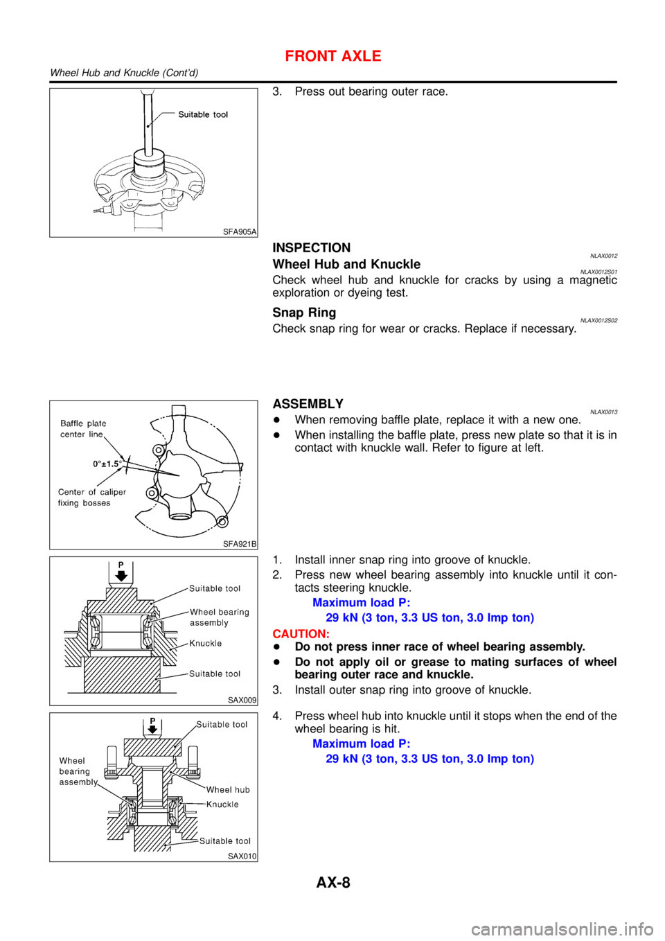
SFA921B
ASSEMBLYNLAX0013+When removing baffle plate, replace it with a new one.
+When installing the baffle plate, press new plate so that it is in
contact with knuckle wall. Refer to figure at left.
SAX009
1. Install inner snap ring into groove of knuckle.
2. Press new wheel bearing assembly into knuckle until it con-
tacts steering knuckle.
Maximum load P:
29 kN (3 ton, 3.3 US ton, 3.0 Imp ton)
CAUTION:
+Do not press inner race of wheel bearing assembly.
+Do not apply oil or grease to mating surfaces of wheel
bearing outer race and knuckle.
3. Install outer snap ring into groove of knuckle.
SAX010
4. Press wheel hub into knuckle until it stops when the end of the
wheel bearing is hit.
Maximum load P:
29 kN (3 ton, 3.3 US ton, 3.0 Imp ton)
FRONT AXLE
Wheel Hub and Knuckle (Cont’d)
AX-8
Page 220 of 3051
SFA182A
5. Check bearing operation.
a. Add load P with press.
Load P:
49.0 kN
(5.0 ton, 5.5 US ton, 4.92 Imp ton)
b. Spin knuckle several turns in both directions.
c. Make sure that wheel bearings operate smoothly.
FRONT AXLE
Wheel Hub and Knuckle (Cont’d)
AX-9
Page 222 of 3051
SFA090A
REMOVALNLAX00141. Remove wheel bearing lock nut.
Brake caliper need not be disconnected. Do not twist or
stretch brake hose when moving components.
SFA153B
2. Remove strut lower mount bolts.
3. Remove brake hose clip.
SFA499A
4. Separate drive shaft from knuckle by lightly tapping it. If it is
hard to remove, use a puller.
Cover boots with shop towel so as not to damage them
when removing drive shaft.
Refer to“Wheel Hub and Knuckle”,“FRONT AXLE”, AX-5.
5. Remove right drive shaft from transaxle.
NAX004
6. Remove left drive shaft from transaxle.
+Pry off drive shaft from transaxle as shown at left.
SFA482-D
INSTALLATIONNLAX0015Transaxle SideNLAX0015S011. Drive a new oil seal to transaxle. Refer to MT-15 or AT-204,
“Replacing Oil Seal”or“Differential Side Oil Seal
Replacement”,“ON-VEHICLE SERVICE”.
2. Set Tool along the inner circumference of oil seal.
FRONT AXLE
Drive Shaft (Cont’d)
AX-11
Page 223 of 3051

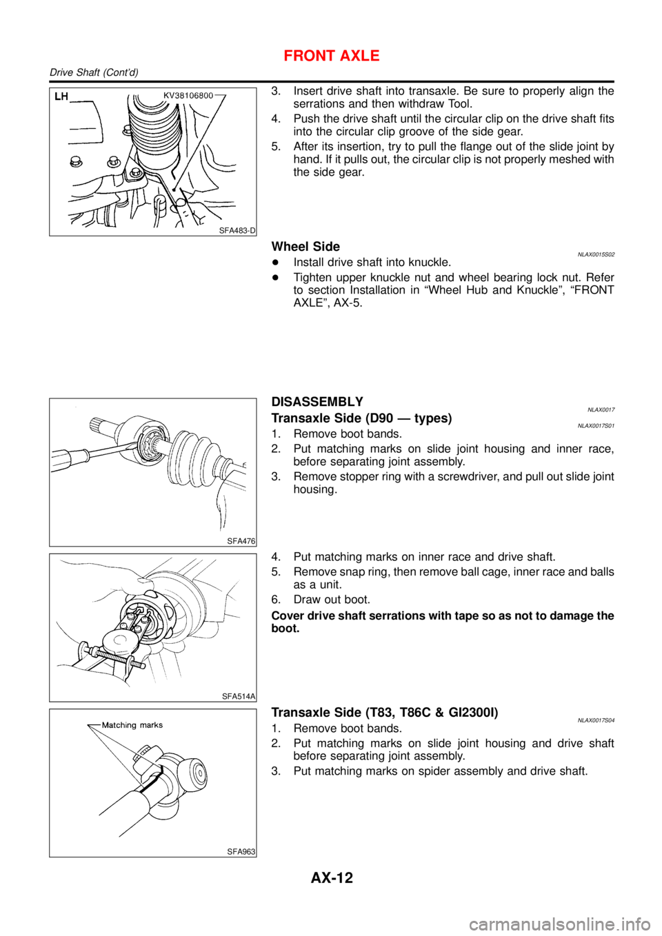
SFA483-D
3. Insert drive shaft into transaxle. Be sure to properly align the
serrations and then withdraw Tool.
4. Push the drive shaft until the circular clip on the drive shaft fits
into the circular clip groove of the side gear.
5. After its insertion, try to pull the flange out of the slide joint by
hand. If it pulls out, the circular clip is not properly meshed with
the side gear.
Wheel SideNLAX0015S02+Install drive shaft into knuckle.
+Tighten upper knuckle nut and wheel bearing lock nut. Refer
to section Installation in“Wheel Hub and Knuckle”,“FRONT
AXLE”, AX-5.
SFA476
DISASSEMBLYNLAX0017Transaxle Side (D90—types)NLAX0017S011. Remove boot bands.
2. Put matching marks on slide joint housing and inner race,
before separating joint assembly.
3. Remove stopper ring with a screwdriver, and pull out slide joint
housing.
SFA514A
4. Put matching marks on inner race and drive shaft.
5. Remove snap ring, then remove ball cage, inner race and balls
as a unit.
6. Draw out boot.
Cover drive shaft serrations with tape so as not to damage the
boot.
SFA963
Transaxle Side (T83, T86C & GI2300I)NLAX0017S041. Remove boot bands.
2. Put matching marks on slide joint housing and drive shaft
before separating joint assembly.
3. Put matching marks on spider assembly and drive shaft.
FRONT AXLE
Drive Shaft (Cont’d)
AX-12