2001 NISSAN ALMERA TINO radio antenna
[x] Cancel search: radio antennaPage 241 of 3051

Precautions When Working On ABSNLBR0149+Use recommended tyres in combination with ABS.
+Please fit tyres or studded tyres, etc. with the same size.
+If different sizes of tyres, or tyres other than the ones rec-
ommended for use with the ABS, are fitted, stopping dis-
tance will increase and control and stability could deterio-
rate.
+When changing brake pads, please use Nissan genuine
parts.
+When fitting radios etc, do not position the radio itself,
antenna, or antenna cables within an area of about 100
mm (3.94 in) of the control unit.
+When doing any work that requires electro-welding, first
remove the control unit.
+Please take care when taking a power supply for the
audio, lamps etc., not to take this from any ABS-related
harness. (Please refer to the electrical wiring diagrams for
ABS-related harnesses)
Wiring Diagrams and Trouble DiagnosisNLBR0003When you read wiring diagrams, refer to the following:
+GI-11,“HOW TO READ WIRING DIAGRAMS”
+EL-10,“POWER SUPPLY ROUTING”
When you perform trouble diagnosis, refer to the following:
+GI-32,“HOW TO FOLLOW TEST GROUPS IN TROUBLE DIAGNOSIS”
+GI-21,“HOW TO PERFORM EFFICIENT DIAGNOSES FOR AN ELECTRICAL INCIDENT”
PRECAUTIONS
Precautions When Working On ABS
BR-4
Page 2103 of 3051

SEL526V
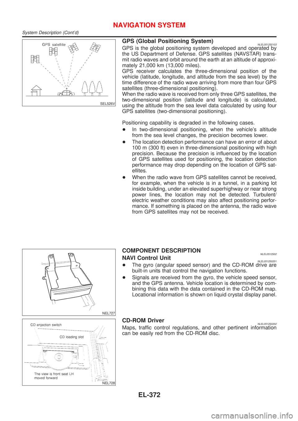
GPS (Global Positioning System)NLEL0512S0103GPS is the global positioning system developed and operated by
the US Department of Defense. GPS satellites (NAVSTAR) trans-
mit radio waves and orbit around the earth at an altitude of approxi-
mately 21,000 km (13,000 miles).
GPS receiver calculates the three-dimensional position of the
vehicle (latitude, longitude, and altitude from the sea level) by the
time difference of the radio wave arriving from more than four GPS
satellites (three-dimensional positioning).
When the radio wave is received from only three GPS satellites, the
two-dimensional position (latitude and longitude) is calculated,
using the altitude from the sea level data calculated by using four
GPS satellites (two-dimensional positioning).
Positioning capability is degraded in the following cases.
+In two-dimensional positioning, when the vehicle's altitude
from the sea level changes, the precision becomes lower.
+The location detection performance can have an error of about
100 m (300 ft) even in three-dimensional positioning with high
precision. Because the precision is influenced by the location
of GPS satellites used for positioning, the location detection
performance may drop depending on the location of GPS sat-
ellites.
+When the radio wave from GPS satellites cannot be received,
for example, when the vehicle is in a tunnel, in a parking lot
inside building, under an elevated superhighway or near strong
power lines, the location may not be detected. Turbulent/
electric weather conditions may also affect positioning perfor-
mance. If something is placed on the antenna, the radio wave
from GPS satellites may not be received.
NEL727
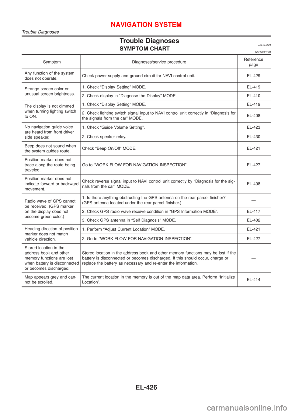
COMPONENT DESCRIPTIONNLEL0512S02NAVI Control UnitNLEL0512S0201+The gyro (angular speed sensor) and the CD-ROM drive are
built-in units that control the navigation functions.
+Signals are received from the gyro, the vehicle speed sensor,
and the GPS antenna. Vehicle location is determined by com-
bining this data with the data contained in the CD-ROM map.
Locational information is shown on liquid crystal display panel.
NEL728
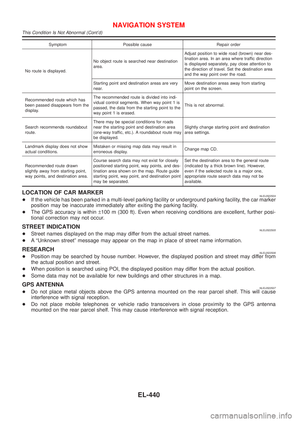
CD-ROM DriverNLEL0512S0202Maps, traffic control regulations, and other pertinent information
can be easily red from the CD-ROM disc.
NAVIGATION SYSTEM
System Description (Cont'd)
EL-372
Page 2157 of 3051

Trouble Diagnoses=NLEL0521SYMPTOM CHARTNLEL0521S01
Symptom Diagnoses/service procedureReference
page
Any function of the system
does not operate.Check power supply and ground circuit for NAVI control unit. EL-429
Strange screen color or
unusual screen brightness.1. Check ªDisplay Settingº MODE. EL-419
2. Check display in ªDiagnose the Displayº MODE. EL-410
The display is not dimmed
when turning lighting switch
to ON.1. Check ªDisplay Settingº MODE. EL-419
2. Check lighting switch signal input to NAVI control unit correctly in ªDiagnosis for
the signals from the carº MODE.EL-408
No navigation guide voice
are heard from front driver
side speaker.1. Check ªGuide Volume Settingº. EL-423
2. Check speaker relay. EL-430
Beep does not sound when
the system guides route.Check ªBeep On/Offº MODE. EL-421
Position marker does not
trace along the route being
traveled.Go to ªWORK FLOW FOR NAVIGATION INSPECTIONº. EL-427
Position marker does not
indicate forward or backward
movement.Check reverse signal input to NAVI control unit correctly by ªDiagnosis for the sig-
nals from the carº MODE.EL-408
Radio wave of GPS cannot
be received. (GPS marker
on the display does not
become green color.)1. Is there anything obstructing the GPS antenna on the rear parcel finisher?
(GPS antenna located under the rear parcel finisher.)Ð
2. Check GPS radio wave receive condition in ªGPS Information MODEº. EL-417
3. Check GPS antenna in ªSelf Diagnosisº MODE. EL-402
Heading direction of position
marker does not match
vehicle direction.1. Perform ªAdjust Current Locationº MODE. EL-421
2. Go to ªWORK FLOW FOR NAVIGATION INSPECTIONº. EL-427
Stored location in the
address book and other
memory functions are lost
when battery is disconnected
or becomes discharged.Stored location in the address book and other memory functions may be lost if the
battery is disconnected or becomes discharged. If this should occur, charge or
replace the battery as necessary and re-enter the information.Ð
Map appears grey and can-
not be scrolled.The current location in the memory is out of the map data area. Perform ªInitialize
Locationº.EL-414
NAVIGATION SYSTEM
Trouble Diagnoses
EL-426
Page 2171 of 3051

Symptom Possible cause Repair order
No route is displayed.No object route is searched near destination
area.Adjust position to wide road (brown) near des-
tination area. In an area where traffic direction
is displayed separately, pay close attention to
the direction of travel. Set the destination area
and the way point over the road.
Starting point and destination areas are very
near.Move destination areas away from starting
point on the screen.
Recommended route which has
been passed disappears from the
display.The recommended route is divided into indi-
vidual control segments. When way point 1 is
passed, the data from the starting point to the
way point 1 is erased.This is not abnormal.
Search recommends roundabout
route.There may be special conditions for roads
near the starting point and destination area
(one-way traffic, etc.). A roundabout route may
be displayed.Slightly change starting point and destination
area settings.
Landmark display does not show
actual conditions.Mistaken or missing map data may result in
erroneous display.Change map CD.
Recommended route drawn
slightly away from starting point,
way points, and destination area.Course search data may not exist for closely
positioned starting point, way points, and des-
tination area shown on the map. Route guide
starting point, way point, and destination point
may be separated.Set the destination area to the general route
(indicated by a thick brown line). However,
even if the selected route is a major one,
appropriate route search data may not be
available.
LOCATION OF CAR MARKERNLEL0522S04+If the vehicle has been parked in a multi-level parking facility or underground parking facility, the car marker
position may be inaccurate immediately after exiting the parking facility.
+The GPS accuracy is within±100 m (300 ft). Even when receiving conditions are excellent, further posi-
tional correction may not occur.
STREET INDICATIONNLEL0522S05+Street names displayed on the map may differ from the actual street names.
+A ªUnknown streetº message may appear on the map in place of street name information.
RESEARCHNLEL0522S06+Position may be searched by house number. However, the displayed position and street may differ from
the actual position and street.
+When position is searched using POI, the displayed position may differ from the actual position.
+Some data may not be available for new buildings and other structures in a map.
GPS ANTENNANLEL0522S07+Do not place metal objects above the GPS antenna mounted on the rear parcel shelf. This will cause
interference with signal reception.
+Do not place mobile telephones or vehicle radio transceivers in close proximity to the GPS antenna
mounted on the rear parcel shelf. This may cause interference with signal reception.
NAVIGATION SYSTEM
This Condition Is Not Abnormal (Cont'd)
EL-440
Page 2701 of 3051

N
NATS (Nissan Anti-theft System)
precautions ................................................... GI-3
NATS (Nissan Anti-theft System) ............ EL-334
NATS - Wiring diagram ............................ EL-338
NVH troubleshooting (AX) ........................... AX-3
NVH troubleshooting (BR) .......................... BR-6
NVH troubleshooting (MT) .......................... MT-9
NVH troubleshooting (ST) ........................... ST-5
NVH troubleshooting (SU) ........................ SU-17
NVH troubleshooting CL ............................. CL-4
NVIS (Nissan vehicle immobiliser sys-
tem) precautions ....................................... GI-3
Neutral position switch . EC-402, 490, 931, 1016
O
Oil pan (engine) ......................... EM-20, 91, 170
Oil pressure (engine) ...................... LC-5, 25, 44
Oil pump (engine) ........................... LC-5, 25, 44
Oil pump regulator valve (engine) .. LC-7, 27, 46
Oil seal replacement (engine) .......... EM-31, 105
On board diagnostic system ... EC-59, 583, 1096
Operating cylinder (clutch) ........................ CL-14
P
PCV (positive crankcase ventilation) ....... EC-42,
576, 1082
PGC/V - Wiring diagram . EC-334, 460, 854, 988
PNP/SW - Wiring diagram ..... EC-404, 491, 933,
1017, 1297
POWER - Wiring diagram ................... EL-14, 24
PST/SW - Wiring diagram ............ EC-524, 1040
Park/Neutral position switch .. EC-402, 490, 931,
1016, 1297
Park/neutral position switch (A/T) .............. AT-66
Park/neutral position switch (M/T) ............ MT-16
Parking brake control ................................ BR-40
Parking lamp .............................................. EL-87
Piston assembly ....................... EM-60, 142, 236
Piston pin inspection ................ EM-54, 134, 226
Piston ring inspection ............... EM-54, 135, 226
Piston to bore clearance .......... EM-56, 137, 228
Power antenna ........................................ EL-233
Power door lock ....................................... EL-257
Power door mirror .................................... EL-241
Power steering fluid level ............................ ST-7
Power steering gear .................................. ST-15
Power steering hydraulic pressure .............. ST-9
Power steering oil pressure switch ........ EC-523,
1039
Power steering oil pump ..................... ST-21, 22
Power steering system bleeding ................. ST-8
Power supply routing ................................... EL-9Power transistor ............................ EC-907, 1010
Power window ......................................... EL-245
Precautions (General) .................................. GI-4
Pressure plate - See Clutch cover ............ CL-22
Pressure test (A/T) ..................................... AT-52
Priming pump .............................. EC-1094,1111
Q
Quick-glow system ................................ EC-1267
R
RR02 - Wiring diagram .. EC-230, 240, 249, 258,
427, 755, 764, 773, 781, 957
RR02/H - Wiring diagram .............. EC-265, 434,
788, 964
Radiator fan - See Cooling fan ................. LC-37
Radiator ......................................... LC-17, 37, 58
Radio - See Audio ................................... EL-208
Rear air spoiler .......................................... BT-38
Rear axle (disc brake type) ....................... AX-23
Rear axle ................................................... AX-21
Rear bumper .............................................. BT-10
Rear combination lamp removal and
installation .............................................. BT-38
Rear disc brake .................................. BR-28, 36
Rear door ................................................... BT-13
Rear heated oxygen sensor (HO2S)
heater .......................... EC-263, 433, 786, 963
Rear heated oxygen sensor (HO2S) ..... EC-227,
237, 246, 256, 426, 752, 761, 770, 779, 956
Rear seat belt ............................................. RS-7
Rear seat ................................................... BT-49
Rear suspension ....................................... SU-17
Rear window defogger ............................ EL-198
Rear window .............................................. BT-59
Refrigerant connection precaution .............. HA-3
Refrigerant general precaution ................... HA-2
Refrigerant lines ........................................ HA-98
Refrigeration cycle .................................... HA-12
Release bearing (clutch) ..................... CL-17, 20
Removal and installation (A/T) ................ AT-206
Resistor ......................................... EC-908, 1011
Reverse idler shaft (M/T) .................... MT-24, 63
Reverse lamp switch (M/T) - See
Back-up lamp switch (M/T) ................... MT-16
Reverse main gear (M/T) .................... MT-25, 63
Revolution sensor (A/T) ....................... AT-83, 89
Road wheel size ......................................... GI-41
Roof trim .................................................... BT-35
Room lamp - See Interior lamp ............... EL-116
ALPHABETICAL INDEX
IDX-6