2001 NISSAN ALMERA TINO tow bar
[x] Cancel search: tow barPage 1515 of 3051

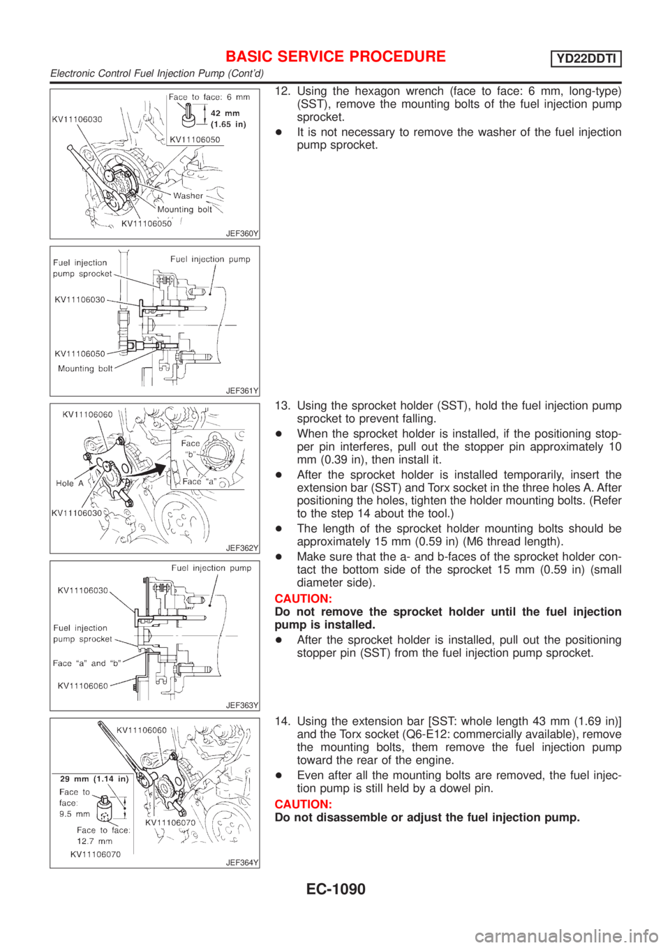
JEF360Y
JEF361Y
12. Using the hexagon wrench (face to face: 6 mm, long-type)
(SST), remove the mounting bolts of the fuel injection pump
sprocket.
+It is not necessary to remove the washer of the fuel injection
pump sprocket.
JEF362Y
JEF363Y
13. Using the sprocket holder (SST), hold the fuel injection pump
sprocket to prevent falling.
+When the sprocket holder is installed, if the positioning stop-
per pin interferes, pull out the stopper pin approximately 10
mm (0.39 in), then install it.
+After the sprocket holder is installed temporarily, insert the
extension bar (SST) and Torx socket in the three holes A. After
positioning the holes, tighten the holder mounting bolts. (Refer
to the step 14 about the tool.)
+The length of the sprocket holder mounting bolts should be
approximately 15 mm (0.59 in) (M6 thread length).
+Make sure that the a- and b-faces of the sprocket holder con-
tact the bottom side of the sprocket 15 mm (0.59 in) (small
diameter side).
CAUTION:
Do not remove the sprocket holder until the fuel injection
pump is installed.
+After the sprocket holder is installed, pull out the positioning
stopper pin (SST) from the fuel injection pump sprocket.
JEF364Y
14. Using the extension bar [SST: whole length 43 mm (1.69 in)]
and the Torx socket (Q6-E12: commercially available), remove
the mounting bolts, them remove the fuel injection pump
toward the rear of the engine.
+Even after all the mounting bolts are removed, the fuel injec-
tion pump is still held by a dowel pin.
CAUTION:
Do not disassemble or adjust the fuel injection pump.
BASIC SERVICE PROCEDUREYD22DDTI
Electronic Control Fuel Injection Pump (Cont'd)
EC-1090
Page 2702 of 3051

S
S/LOCK - Wiring diagram ................ EL-260, 286
S/SIG - Wiring diagram ................. EC-512, 1028
SAE J1930 terminology list ........................ GI-48
SHIFT - Wiring diagram ........................... AT-196
SROOF - Wiring diagram ........................ EL-238
SRS - See Supplemental Restraint
System ................................................... RS-16
START - Wiring diagram ........................... SC-14
STOP/L - Wiring diagram .......................... EL-91
SWL/V - Wiring diagram ................. EC-366, 481
Seal - See Exterior .................................... BT-38
Seat belt pre-tensioner disposal ............... RS-30
Seat belt pre-tensioner ............................... RS-3
Seat belt, front ............................................ RS-5
Seat belt, rear ............................................. RS-7
Seat, front .................................................. BT-46
Seat, rear ................................................... BT-49
Self-diagnostic results ............ EC-73, 598, 1098
Shift control components (M/T) .......... MT-26, 64
Shift fork (M/T) .................................... MT-26, 64
Shift lever .................................................. MT-23
Shift lock system ...................................... AT-195
Shock absorber (front) .............................. SU-11
Shock absorber (rear) ............................... SU-23
Side air bag ............................................... RS-28
Side trim .................................................... BT-28
Speedometer ........................................... EL-130
Spiral cable ............................................... RS-24
Spring (Wheelarch) height .......................... SU-6
Stabilizer bar (front) .................................. SU-12
Stall test (A/T) ............................................ AT-51
Standardized relay ....................................... EL-7
Start signal .......................... EC-511, 1027, 1293
Starter ....................................................... SC-17
Starting system ......................................... SC-13
Steering linkage ......................................... ST-15
Steering switch .......................................... EL-67
Steering wheel and column ....................... ST-10
Steering wheel play ..................................... ST-6
Steering wheel turning force ....................... ST-8
Stop lamp .................................................. EL-91
Striking rod (M/T) ................................ MT-26, 64
Strut (front) ................................................ SU-10
Strut (rear) ................................................. SU-22
Sub-gear (M/T) .......................................... MT-25
Sunroof, electric ....................................... EL-238
Sunroof ...................................................... BT-51
Super lock ................................................ EL-281
Supplemental Restraint System ............... RS-16
Swirl control valve control solenoid
valve .................................. EC-366, 481, 1285
Symbols and abbreviations .......................... GI-9
Symptom matrix chart ........... EC-124, 648, 1116
Synchronizer (M/T) ............................. MT-25, 63
System readiness test (SRT) code ... EC-62, 586
T
TCM circuit diagram ................................... AT-13
TCM inspection table ................................. AT-58
TP/SW - Wiring diagram ................. EC-354, 874
TPS - Wiring diagram ..................... EC-178, 703
TURN - Wiring diagram ........................... EL-102
Tachometer .............................................. EL-130
Tail lamp .................................................... EL-87
Thermostat .................................... LC-15, 35, 57
Three way catalyst precautions ................... GI-6
Three way catalyst .......................... EC-327, 848
Throttle position sensor (TPS) ........ EC-175, 700
Throttle position sensor adjustment .. EC-99, 623
Throttle position switch ................... AT-111, 145,
EC-352, 872
Throwout bearing - See Clutch release
bearing ............................................. CL-17, 20
Tie-rod ball joints ....................................... ST-18
Tie-rod ........................................................ ST-15
Tightening torque of standard bolts ........... GI-47
Timing belt .......................................... EM-22, 96
Timing chain ........................................... EM-175
Tire size ...................................................... GI-41
Torque converter installation .................... AT-207
Tow truck towing ........................................ GI-45
Transmission case (M/T) .................... MT-24, 62
Tread-FR&RR (Dimensions) ...................... GI-41
Trim ............................................................ BT-28
Trouble diagnoses ...................................... GI-31
Trunk lid finisher ........................................ BT-31
Trunk lid opener - See Trunk lid ................ BT-10
Trunk lid trim .............................................. BT-31
Trunk lid ..................................................... BT-10
Trunk room trim ......................................... BT-31
Turn signal lamp ...................................... EL-101
Two trip detection logic ..................... EC-59, 583
Two-pole lift ................................................ GI-44
U
Under body ................................................ BT-68
V
VSS - Wiring diagram ........... EC-340, 860, 1172
Vacuum hose (brake system) ................... BR-18
Vacuum hose drawing (Engine control) ... EC-33,
567, 1077
Vacuum pump ........................................... BR-20
Valve clearance ................................ EM-42, 214
Valve guide ............................... EM-38, 116, 205
Valve lifter ................................................. EM-41
Valve seat ................................. EM-40, 117, 207
Valve spring .............................. EM-41, 119, 209
ALPHABETICAL INDEX
IDX-7