Page 66 of 3051
Diagnostic ProcedureNLAT0330
1 CHECK TCM POWER SOURCE
1. Turn ignition switch to ªONº position.
(Do not start engine.)
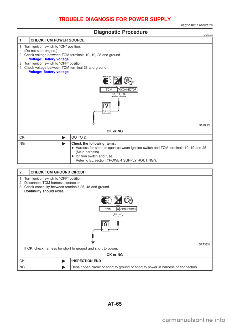
2. Check voltage between TCM terminals 10, 19, 28 and ground.
Voltage: Battery voltage
3. Turn ignition switch to ªOFFº position.
4. Check voltage between TCM terminal 28 and ground.
Voltage: Battery voltage
SAT332J
OK or NG
OK©GO TO 2.
NG©Check the following items:
+Harness for short or open between ignition switch and TCM terminals 10, 19 and 25
(Main harness)
+Ignition switch and fuse
Refer to EL section (ªPOWER SUPPLY ROUTINGº).
2 CHECK TCM GROUND CIRCUIT
1. Turn ignition switch to ªOFFº position.
2. Disconnect TCM harness connector.
3. Check continuity between terminals 25, 48 and ground.
Continuity should exist.
SAT333J
If OK, check harness for short to ground and short to power.
OK or NG
OK©INSPECTION END
NG©Repair open circuit or short to ground or short to power in harness or connectors.
TROUBLE DIAGNOSIS FOR POWER SUPPLY
Diagnostic Procedure
AT-65
Page 71 of 3051
Diagnostic ProcedureNLAT0033
1 CHECK PNP SWITCH CIRCUIT (With CONSULT-II)
With CONSULT-II
1. Turn ignition switch to ªONº position.
(Do not start engine.)
2. Select ªTCM INPUT SIGNALSº in ªDATA MONITORº mode for ªCVTº with CONSULT-II.
SAT250K
3. Read out ªP/Nº, ªRº, ªDº and ªLº position switches moving selector lever to each position.
Check the signal of the selector lever position is indicated properly.
OK or NG
OK©GO TO 3.
NG©Check the following items:
+PNP switch
Refer to ªComponent Inspectionº, AT-72.
+Harness for short or open between ignition switch and PNP switch (Main harness)
+Harness for short or open between PNP switch and TCM (Main harness)
+Ignition switch and fuse
Refer to EL section (ªPOWER SUPPLY ROUTINGº).
2 CHECK PNP SWITCH CIRCUIT (Without CONSULT-II)
Without CONSULT-II
1. Turn ignition switch to ªONº position.
(Do not start engine.)
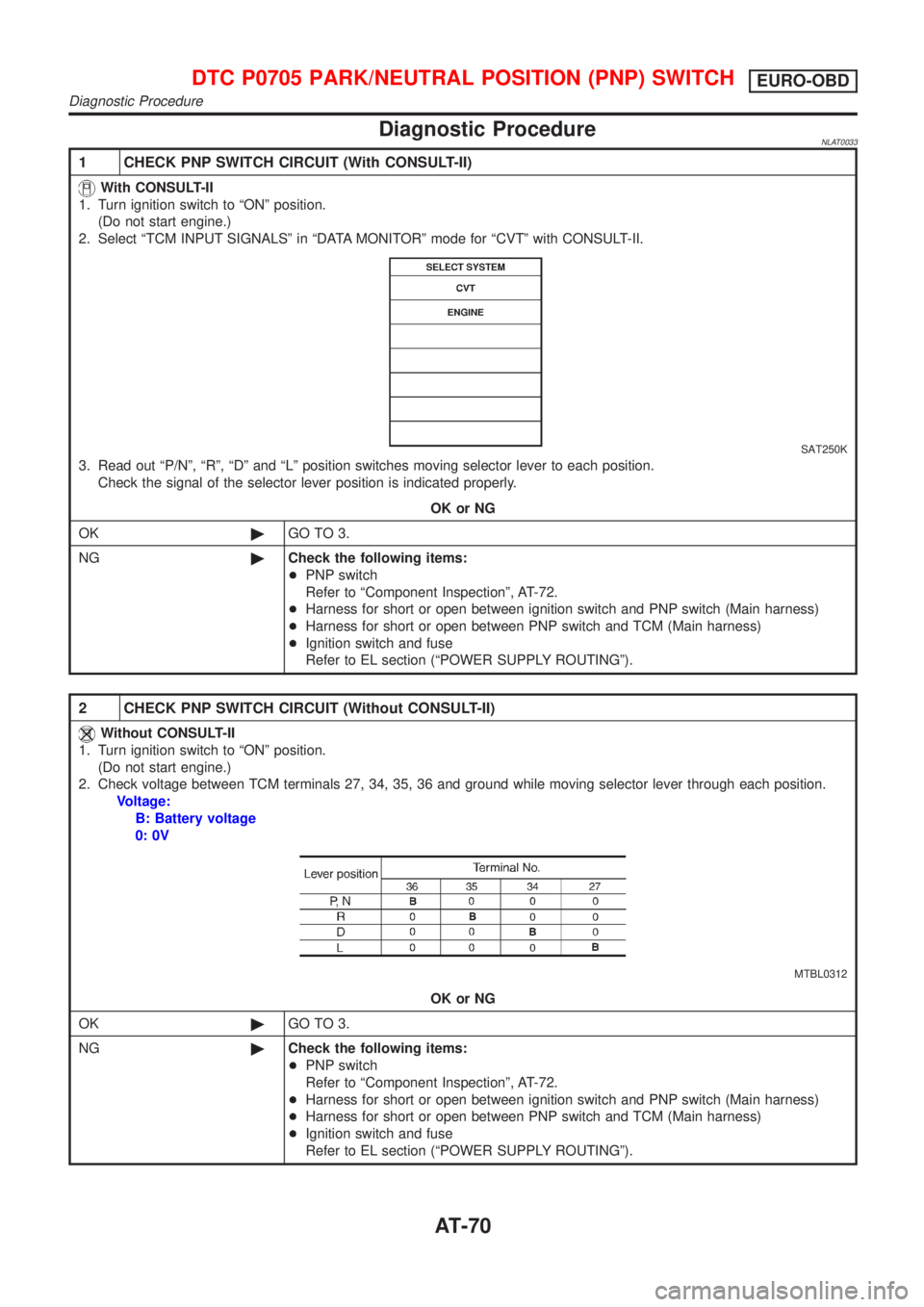
2. Check voltage between TCM terminals 27, 34, 35, 36 and ground while moving selector lever through each position.
Voltage:
B: Battery voltage
0: 0V
MTBL0312
OK or NG
OK©GO TO 3.
NG©Check the following items:
+PNP switch
Refer to ªComponent Inspectionº, AT-72.
+Harness for short or open between ignition switch and PNP switch (Main harness)
+Harness for short or open between PNP switch and TCM (Main harness)
+Ignition switch and fuse
Refer to EL section (ªPOWER SUPPLY ROUTINGº).
DTC P0705 PARK/NEUTRAL POSITION (PNP) SWITCHEURO-OBD
Diagnostic Procedure
AT-70
Page 185 of 3051
PNP Switch, Stop Lamp Switch and Throttle
Position Switch
NLAT0290SYMPTOM:
SPORT indicator lamp does not come on in TCM self-diagnos-
tic procedure even the lamp circuit is good.
DESCRIPTIONNLAT0290S01+PNP switch
+The PNP switch assemble includes a transmission position
switch. The transmission position switch detects the selector
position and sends a signal to the TCM.
+Stop lamp switch
Detects the stop lamp switch position (ON or OFF) and sends
a signal to the TCM
+Throttle position switch.
Consists of a wide open throttle position switch and a closed
throttle position switch.
The wide open throttle position switch sends a signal to the
TCM when the throttle valve is open at least 1/2 of the full
throttle position. The closed throttle position switch sends a
signal to the TCM when the throttle valve is fully closed.
Diagnostic ProcedureNLAT0291
1 CHECK PNP SWITCH CIRCUIT (With CONSULT-II)
With CONSULT-II
1. Turn ignition switch to ªONº position.
(Do not start engine.)
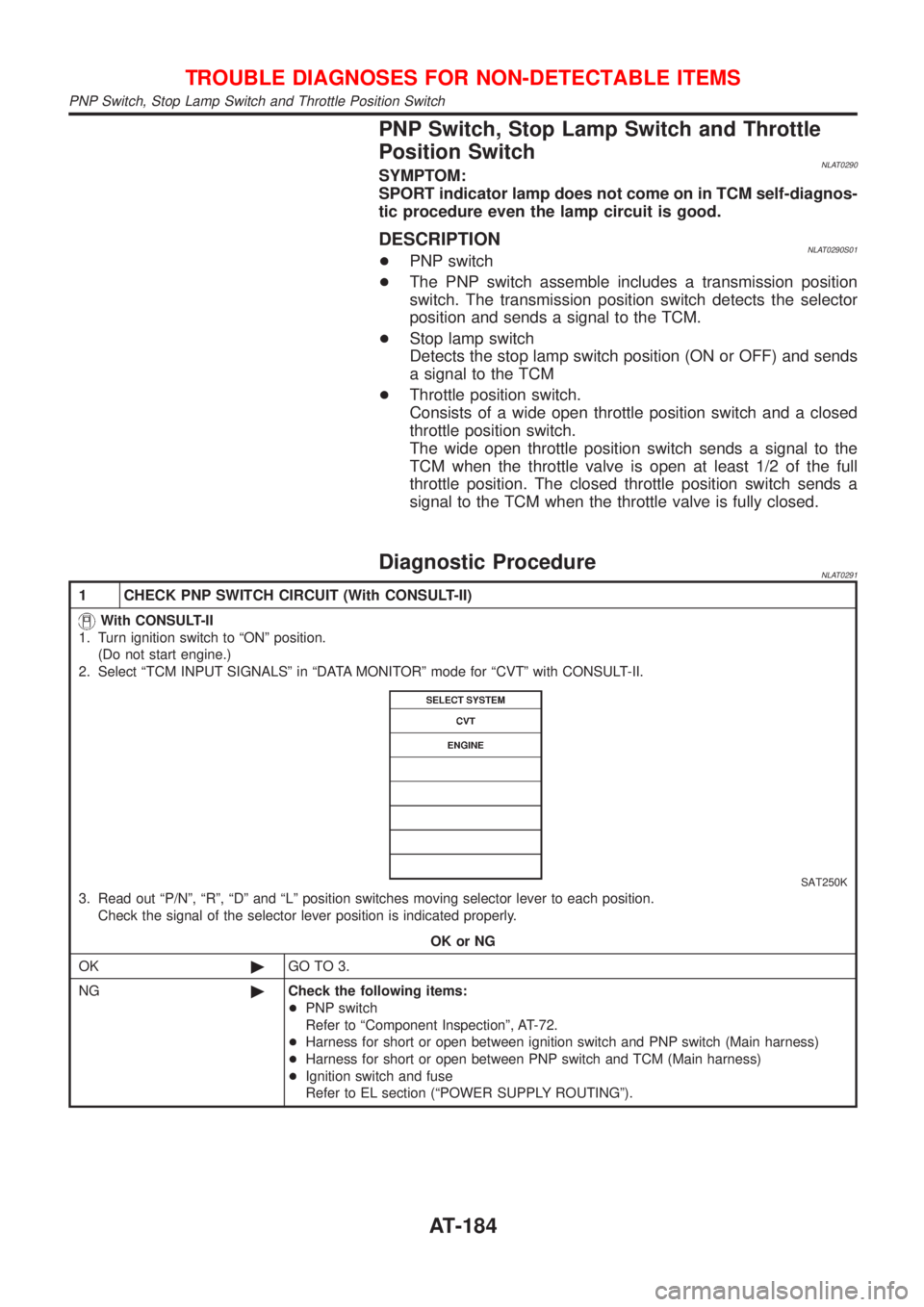
2. Select ªTCM INPUT SIGNALSº in ªDATA MONITORº mode for ªCVTº with CONSULT-II.
SAT250K
3. Read out ªP/Nº, ªRº, ªDº and ªLº position switches moving selector lever to each position.
Check the signal of the selector lever position is indicated properly.
OK or NG
OK©GO TO 3.
NG©Check the following items:
+PNP switch
Refer to ªComponent Inspectionº, AT-72.
+Harness for short or open between ignition switch and PNP switch (Main harness)
+Harness for short or open between PNP switch and TCM (Main harness)
+Ignition switch and fuse
Refer to EL section (ªPOWER SUPPLY ROUTINGº).
TROUBLE DIAGNOSES FOR NON-DETECTABLE ITEMS
PNP Switch, Stop Lamp Switch and Throttle Position Switch
AT-184
Page 186 of 3051
2 CHECK PNP SWITCH CIRCUIT (Without CONSULT-II)
With CONSULT-II
1. Turn ignition switch to ªONº position.
(Do not start engine.)
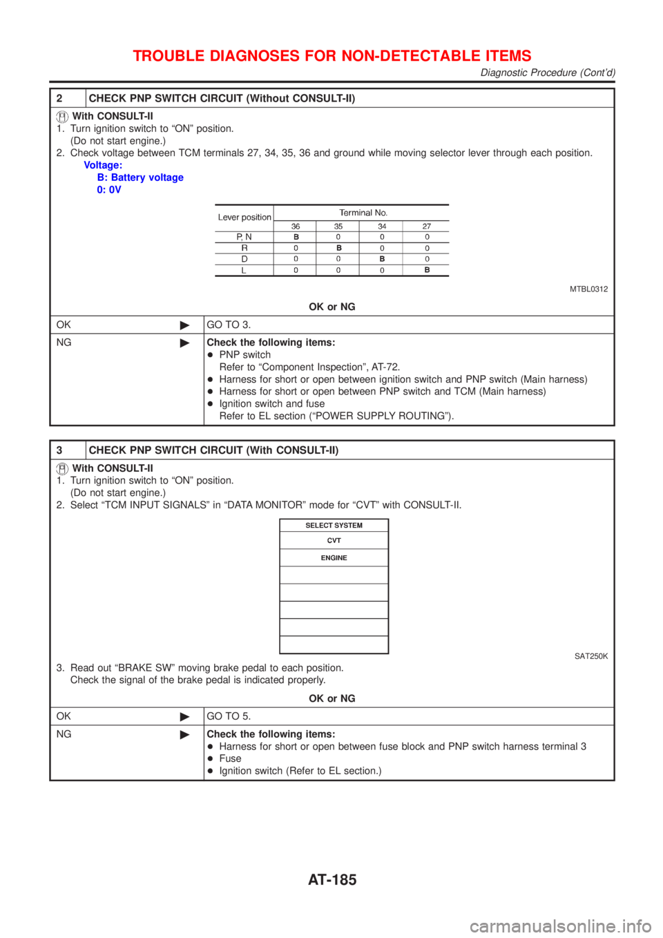
2. Check voltage between TCM terminals 27, 34, 35, 36 and ground while moving selector lever through each position.
Voltage:
B: Battery voltage
0: 0V
MTBL0312
OK or NG
OK©GO TO 3.
NG©Check the following items:
+PNP switch
Refer to ªComponent Inspectionº, AT-72.
+Harness for short or open between ignition switch and PNP switch (Main harness)
+Harness for short or open between PNP switch and TCM (Main harness)
+Ignition switch and fuse
Refer to EL section (ªPOWER SUPPLY ROUTINGº).
3 CHECK PNP SWITCH CIRCUIT (With CONSULT-II)
With CONSULT-II
1. Turn ignition switch to ªONº position.
(Do not start engine.)
2. Select ªTCM INPUT SIGNALSº in ªDATA MONITORº mode for ªCVTº with CONSULT-II.
SAT250K
3. Read out ªBRAKE SWº moving brake pedal to each position.
Check the signal of the brake pedal is indicated properly.
OK or NG
OK©GO TO 5.
NG©Check the following items:
+Harness for short or open between fuse block and PNP switch harness terminal 3
+Fuse
+Ignition switch (Refer to EL section.)
TROUBLE DIAGNOSES FOR NON-DETECTABLE ITEMS
Diagnostic Procedure (Cont'd)
AT-185
Page 187 of 3051
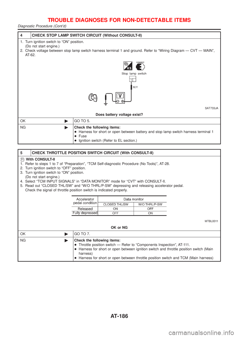
4 CHECK STOP LAMP SWITCH CIRCUIT (Without CONSULT-II)
1. Turn ignition switch to ªONº position.
(Do not start engine.)
2. Check voltage between stop lamp switch harness terminal 1 and ground. Refer to ªWiring Diagram Ð CVT Ð MAINº,
AT-62.
SAT733JA
Does battery voltage exist?
OK©GO TO 5.
NG©Check the following items:
+Harness for short or open between battery and stop lamp switch harness terminal 1
+Fuse
+Ignition switch (Refer to EL section.)
5 CHECK THROTTLE POSITION SWITCH CIRCUIT (With CONSULT-II)
With CONSULT-II
1. Refer to steps 1 to 7 of ªPreparationº, ªTCM Self-diagnostic Procedure (No Tools)º, AT-28.
2. Turn ignition switch to ªOFFº position.
3. Turn ignition switch to ªONº position.
(Do not start engine.)
4. Select ªTCM INPUT SIGNALSº in ªDATA MONITORº mode for ªCVTº with CONSULT-II.
5. Read out ªCLOSED THL/SWº and ªW/O THRL/P-SWº depressing and releasing accelerator pedal.
Check the signal of throttle position switch is indicated properly.
MTBL0011
OK or NG
OK©GO TO 7.
NG©Check the following items:
+Throttle position switch Ð Refer to ªComponents Inspectionº, AT-111.
+Harness for short or open between ignition switch and throttle position switch (Main
harness)
+Harness for short or open between throttle position switch and TCM (Main harness)
TROUBLE DIAGNOSES FOR NON-DETECTABLE ITEMS
Diagnostic Procedure (Cont'd)
AT-186
Page 193 of 3051
SAT261K
SPORT Indicator Lamp Does Not Come On=NLAT0295SYMPTOM:
SPORT indicator lamp does not come on for about 2 seconds
when turning ignition switch to ªONº.
1 CHECK TCM POWER SOURCE
SAT262K
1. Turn ignition switch to ªOFFº position.
2. Check voltage between TCM terminal 28 and ground.
Voltage: Battery voltage
OK or NG
OK©GO TO 2.
NG©Check the following items:
+Harness for short or open between battery terminal and TCM terminal 28 (Main har-
ness).
+Refer to ªWiring Diagram Ð AT Ð MAINº, AT-62.
+Ignition switch and fuse Refer to EL section, ªPOWER SUPPLY ROUTINGº.
TROUBLE DIAGNOSES FOR SYMPTOMS
SPORT Indicator Lamp Does Not Come On
AT-192
Page 194 of 3051
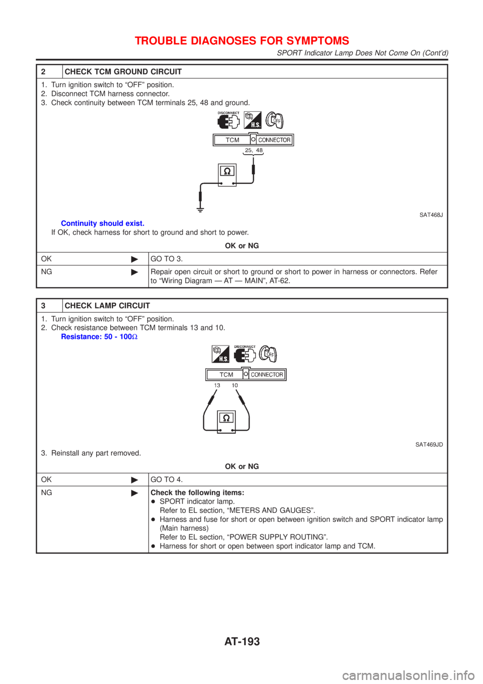
2 CHECK TCM GROUND CIRCUIT
1. Turn ignition switch to ªOFFº position.
2. Disconnect TCM harness connector.
3. Check continuity between TCM terminals 25, 48 and ground.
SAT468J
Continuity should exist.
If OK, check harness for short to ground and short to power.
OK or NG
OK©GO TO 3.
NG©Repair open circuit or short to ground or short to power in harness or connectors. Refer
to ªWiring Diagram Ð AT Ð MAINº, AT-62.
3 CHECK LAMP CIRCUIT
1. Turn ignition switch to ªOFFº position.
2. Check resistance between TCM terminals 13 and 10.
Resistance: 50 - 100W
SAT469JD
3. Reinstall any part removed.
OK or NG
OK©GO TO 4.
NG©Check the following items:
+SPORT indicator lamp.
Refer to EL section, ªMETERS AND GAUGESº.
+Harness and fuse for short or open between ignition switch and SPORT indicator lamp
(Main harness)
Refer to EL section, ªPOWER SUPPLY ROUTINGº.
+Harness for short or open between sport indicator lamp and TCM.
TROUBLE DIAGNOSES FOR SYMPTOMS
SPORT Indicator Lamp Does Not Come On (Cont'd)
AT-193
Page 199 of 3051
Diagnostic ProcedureNLAT0319SYMPTOM 1:
+Selector lever cannot be moved from ªPº position with key
in ON position and brake pedal applied.
+Selector lever can be moved from ªPº position with key in
ON position and brake pedal released.
+Selector lever can be moved from ªPº position when key
is removed from key cylinder.
SYMPTOM 2:
Ignition key cannot be removed when selector lever is set to
ªPº position. It can be removed when selector lever is set to
any position except ªPº.
1 CHECK KEY INTERLOCK CABLE
Check key interlock cable for damage.
OK or NG
OK©GO TO 2.
NG©Repair key interlock cable. Refer to AT-202.
2 CHECK SELECTOR LEVER POSITION
Check selector lever position for damage.
OK or NG
OK©GO TO 3.
NG©Check selector lever. Refer to ªON-VEHICLE SERVICE Ð PNP Switch and Control
Cable Adjustmentº, AT-204.
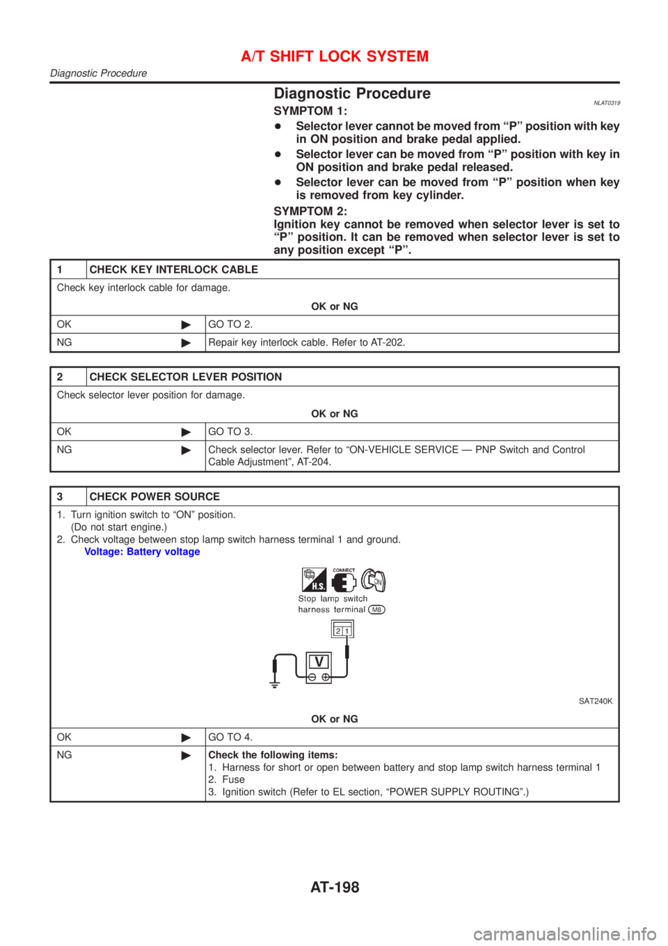
3 CHECK POWER SOURCE
1. Turn ignition switch to ªONº position.
(Do not start engine.)
2. Check voltage between stop lamp switch harness terminal 1 and ground.
Voltage: Battery voltage
SAT240K
OK or NG
OK©GO TO 4.
NG©Check the following items:
1. Harness for short or open between battery and stop lamp switch harness terminal 1
2. Fuse
3. Ignition switch (Refer to EL section, ªPOWER SUPPLY ROUTINGº.)
A/T SHIFT LOCK SYSTEM
Diagnostic Procedure
AT-198