2001 NISSAN ALMERA TINO set clock
[x] Cancel search: set clockPage 534 of 3051
17 ADJUSTMENT THROTTLE POSITION SWITCH CLOSED POSITION-II
Without CONSULT-II
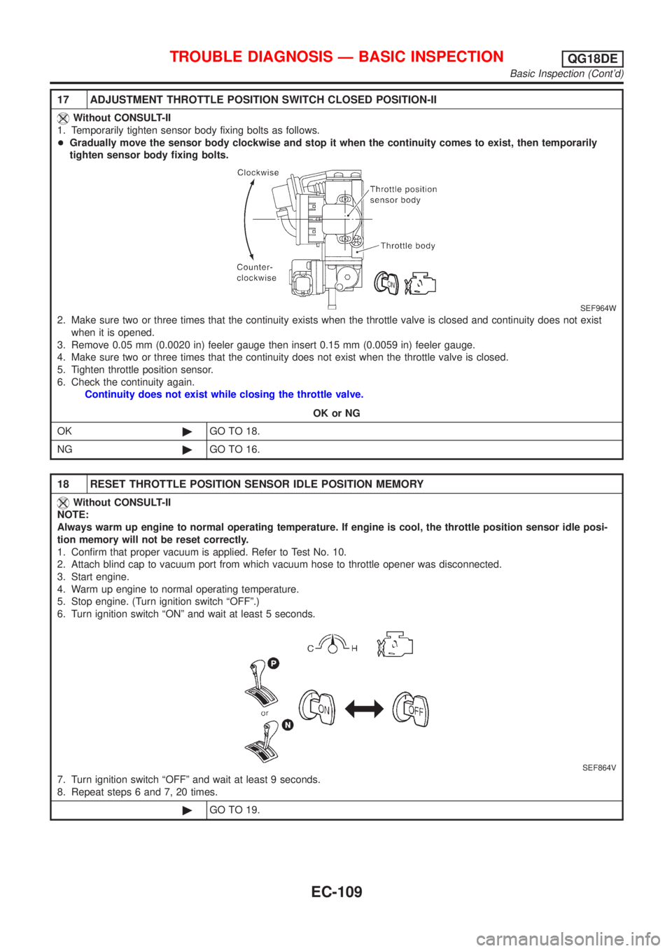
1. Temporarily tighten sensor body fixing bolts as follows.
+Gradually move the sensor body clockwise and stop it when the continuity comes to exist, then temporarily
tighten sensor body fixing bolts.
SEF964W
2. Make sure two or three times that the continuity exists when the throttle valve is closed and continuity does not exist
when it is opened.
3. Remove 0.05 mm (0.0020 in) feeler gauge then insert 0.15 mm (0.0059 in) feeler gauge.
4. Make sure two or three times that the continuity does not exist when the throttle valve is closed.
5. Tighten throttle position sensor.
6. Check the continuity again.
Continuity does not exist while closing the throttle valve.
OK or NG
OK©GO TO 18.
NG©GO TO 16.
18 RESET THROTTLE POSITION SENSOR IDLE POSITION MEMORY
Without CONSULT-II
NOTE:
Always warm up engine to normal operating temperature. If engine is cool, the throttle position sensor idle posi-
tion memory will not be reset correctly.
1. Confirm that proper vacuum is applied. Refer to Test No. 10.
2. Attach blind cap to vacuum port from which vacuum hose to throttle opener was disconnected.
3. Start engine.
4. Warm up engine to normal operating temperature.
5. Stop engine. (Turn ignition switch ªOFFº.)
6. Turn ignition switch ªONº and wait at least 5 seconds.
SEF864V
7. Turn ignition switch ªOFFº and wait at least 9 seconds.
8. Repeat steps 6 and 7, 20 times.
©GO TO 19.
TROUBLE DIAGNOSIS Ð BASIC INSPECTIONQG18DE
Basic Inspection (Cont'd)
EC-109
Page 1058 of 3051
15 ADJUSTMENT THROTTLE POSITION SWITCH CLOSED POSITION-II
Without CONSULT-II
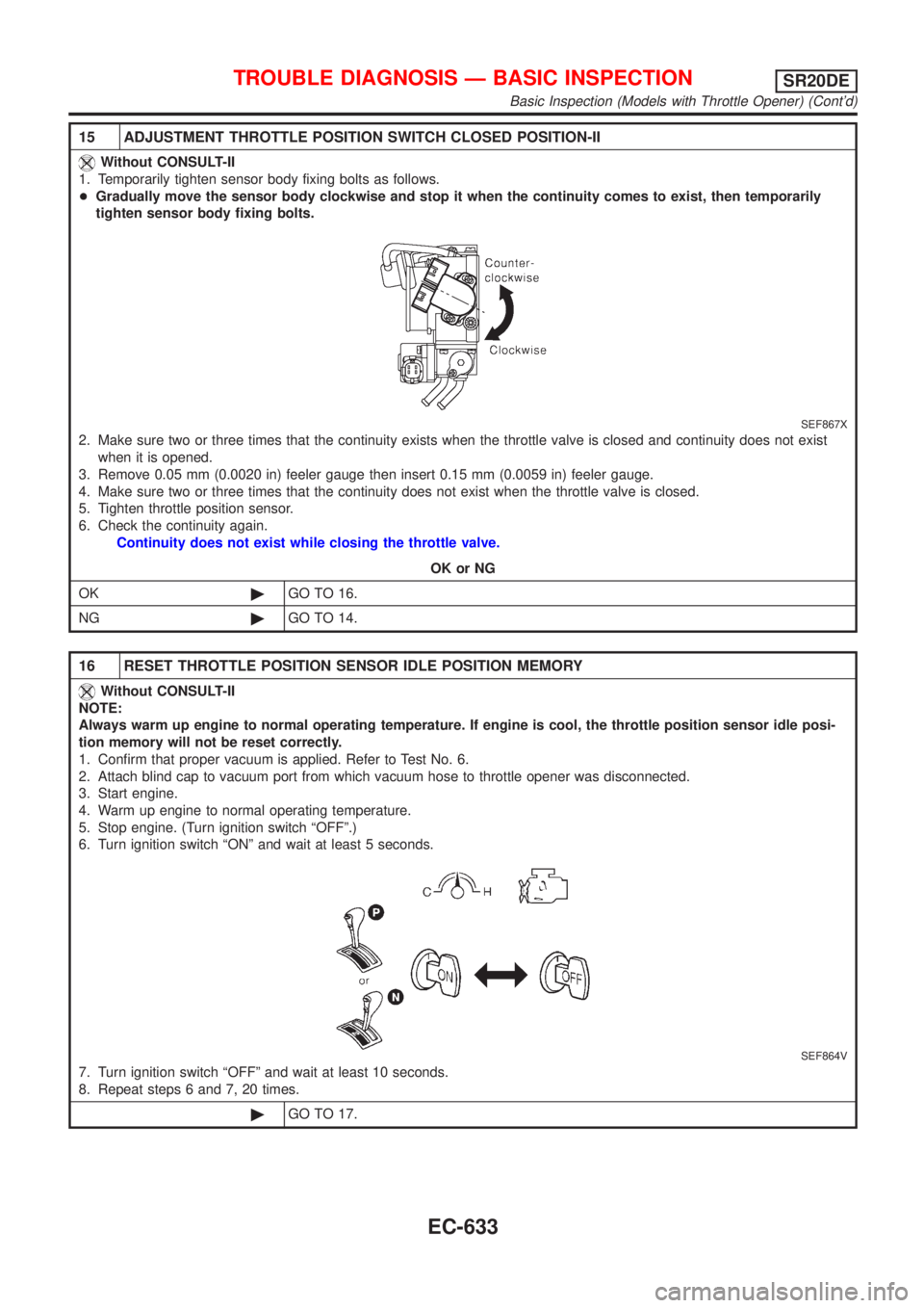
1. Temporarily tighten sensor body fixing bolts as follows.
+Gradually move the sensor body clockwise and stop it when the continuity comes to exist, then temporarily
tighten sensor body fixing bolts.
SEF867X
2. Make sure two or three times that the continuity exists when the throttle valve is closed and continuity does not exist
when it is opened.
3. Remove 0.05 mm (0.0020 in) feeler gauge then insert 0.15 mm (0.0059 in) feeler gauge.
4. Make sure two or three times that the continuity does not exist when the throttle valve is closed.
5. Tighten throttle position sensor.
6. Check the continuity again.
Continuity does not exist while closing the throttle valve.
OK or NG
OK©GO TO 16.
NG©GO TO 14.
16 RESET THROTTLE POSITION SENSOR IDLE POSITION MEMORY
Without CONSULT-II
NOTE:
Always warm up engine to normal operating temperature. If engine is cool, the throttle position sensor idle posi-
tion memory will not be reset correctly.
1. Confirm that proper vacuum is applied. Refer to Test No. 6.
2. Attach blind cap to vacuum port from which vacuum hose to throttle opener was disconnected.
3. Start engine.
4. Warm up engine to normal operating temperature.
5. Stop engine. (Turn ignition switch ªOFFº.)
6. Turn ignition switch ªONº and wait at least 5 seconds.
SEF864V
7. Turn ignition switch ªOFFº and wait at least 10 seconds.
8. Repeat steps 6 and 7, 20 times.
©GO TO 17.
TROUBLE DIAGNOSIS Ð BASIC INSPECTIONSR20DE
Basic Inspection (Models with Throttle Opener) (Cont'd)
EC-633
Page 1066 of 3051
9 ADJUST THROTTLE POSITION SENSOR IDLE POSITION
Without CONSULT-II
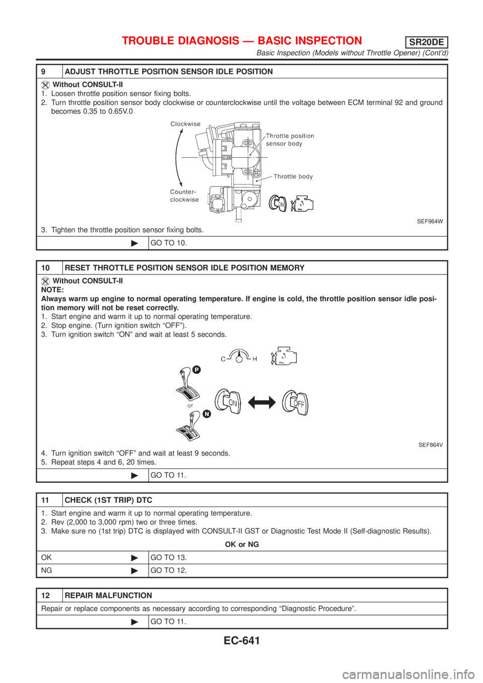
1. Loosen throttle position sensor fixing bolts.
2. Turn throttle position sensor body clockwise or counterclockwise until the voltage between ECM terminal 92 and ground
becomes 0.35 to 0.65V.0
SEF964W
3. Tighten the throttle position sensor fixing bolts.
©GO TO 10.
10 RESET THROTTLE POSITION SENSOR IDLE POSITION MEMORY
Without CONSULT-II
NOTE:
Always warm up engine to normal operating temperature. If engine is cold, the throttle position sensor idle posi-
tion memory will not be reset correctly.
1. Start engine and warm it up to normal operating temperature.
2. Stop engine. (Turn ignition switch ªOFFº).
3. Turn ignition switch ªONº and wait at least 5 seconds.
SEF864V
4. Turn ignition switch ªOFFº and wait at least 9 seconds.
5. Repeat steps 4 and 6, 20 times.
©GO TO 11.
11 CHECK (1ST TRIP) DTC
1. Start engine and warm it up to normal operating temperature.
2. Rev (2,000 to 3,000 rpm) two or three times.
3. Make sure no (1st trip) DTC is displayed with CONSULT-II GST or Diagnostic Test Mode II (Self-diagnostic Results).
OK or NG
OK©GO TO 13.
NG©GO TO 12.
12 REPAIR MALFUNCTION
Repair or replace components as necessary according to corresponding ªDiagnostic Procedureº.
©GO TO 11.
TROUBLE DIAGNOSIS Ð BASIC INSPECTIONSR20DE
Basic Inspection (Models without Throttle Opener) (Cont'd)
EC-641
Page 1733 of 3051
Electrical Components Inspection ...........................164
WARNING CHIME.......................................................165
Component Parts and Harness Connector
Location ...................................................................165
System Description ..................................................165
Wiring Diagram - CHIME - ......................................166
Trouble Diagnoses...................................................170
FRONT WIPER AND WASHER..................................176
System Description ..................................................176
Wiring Diagram - WIPER - ......................................178
Removal and Installation .........................................182
Washer Nozzle Adjustment .....................................183
Washer Tube Layout ...............................................183
REAR WIPER AND WASHER....................................184
Wiring Diagram - WIP/R -........................................184
Removal and Installation .........................................188
Washer Nozzle Adjustment .....................................188
Washer Tube Layout ...............................................189
HEADLAMP WASHER................................................190
Wiring Diagram - HLC - ...........................................190
Washer Tube Layout ...............................................192
HORN...........................................................................193
Wiring Diagram - HORN - .......................................193
CIGARETTE LIGHTER................................................195
Wiring Diagram - CIGAR -.......................................195
CLOCK.........................................................................196
Wiring Diagram - CLOCK -......................................196
REAR WINDOW DEFOGGER.....................................198
System Description ..................................................198
Wiring Diagram - DEF - ...........................................199
Trouble Diagnoses...................................................203
Electrical Components Inspection ...........................205
Filament Check ........................................................206
Filament Repair .......................................................207
AUDIO..........................................................................208
System Description ..................................................208
Schematic ................................................................210
Wiring Diagram - AUDIO - .......................................212
Trouble Diagnoses...................................................230
Inspection.................................................................232
AUDIO ANTENNA.......................................................233
Location of Antenna .................................................233
Antenna Rod Replacement .....................................233
HEATED SEAT............................................................234
Wiring Diagram - H/SEAT - .....................................234
POWER SUNROOF.....................................................238
Wiring Diagram - SROOF - .....................................238
Trouble Diagnoses...................................................240
DOOR MIRROR...........................................................241
Wiring Diagram - MIRROR - ...................................241
POWER WINDOW.......................................................245
System Description ..................................................245Schematic ................................................................247
Wiring Diagram - WINDOW - ..................................248
Trouble Diagnoses...................................................256
POWER DOOR LOCK.................................................257
Component Parts and Harness Connector
Location/LHD Models ..............................................257
System Description/LHD Models .............................257
Schematic/LHD Models ...........................................258
Wiring Diagram - D/LOCK -/LHD Models................260
Trouble Diagnoses/LHD Models..............................272
POWER DOOR LOCK - SUPER LOCK -...................281
System Description/RHD Models ............................281
Schematic/RHD Models...........................................284
Wiring Diagram - S/LOCK -/RHD Models ...............286
Trouble Diagnoses/RHD Models .............................300
MULTI-REMOTE CONTROL SYSTEM.......................314
System Description ..................................................314
Wiring Diagram - MULTI - .......................................315
Trouble Diagnoses...................................................319
ID Code Entry Procedure ........................................324
Remote Controller Battery Replacement.................325
TIME CONTROL UNIT................................................326
Description ...............................................................326
Trouble Diagnoses...................................................327
Schematic ................................................................330
NATS (NISSAN ANTI-THEFT SYSTEM).....................334
Component Parts and Harness Connector
Location ...................................................................334
System Description ..................................................334
System Composition ................................................335
Schematic ................................................................336
Wiring Diagram - NATS -.........................................338
CONSULT-II .............................................................346
Trouble Diagnoses...................................................349
How to Replace NATS IMMU ..................................369
NAVIGATION SYSTEM...............................................370
Precautions ..............................................................370
Component Parts Location ......................................370
System Description ..................................................370
Schematic ................................................................379
Wiring Diagram - NAVI - ..........................................381
Self-diagnosis Mode ................................................401
Confirmation/Adjustment Mode ...............................404
Control Panel Mode .................................................416
Guide Volume Setting ..............................................423
Anti-theft System .....................................................424
CONSULT-II .............................................................425
Trouble Diagnoses...................................................426
This Condition Is Not Abnormal...............................432
Program Loading .....................................................441
ELECTRICAL UNITS LOCATION...............................442
Engine Compartment ...............................................442
CONTENTS(Cont'd)
EL-2
Page 2137 of 3051
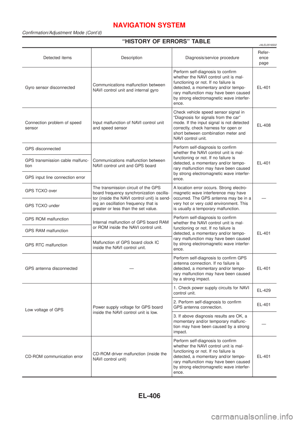
ªHISTORY OF ERRORSº TABLE=NLEL0516S02
Detected items Description Diagnosis/service procedureRefer-
ence
page
Gyro sensor disconnectedCommunications malfunction between
NAVI control unit and internal gyroPerform self-diagnosis to confirm
whether the NAVI control unit is mal-
functioning or not. If no failure is
detected, a momentary and/or tempo-
rary malfunction may have been caused
by strong electromagnetic wave interfer-
ence.EL-401
Connection problem of speed
sensorInput malfunction of NAVI control unit
and speed sensorCheck vehicle speed sensor signal in
ªDiagnosis for signals from the carº
mode. If the input signal is not detected
correctly, check harness for open or
short between combination meter and
NAVI control unit.EL-408
GPS disconnected
Communications malfunction between
NAVI control unit and GPS boardPerform self-diagnosis to confirm
whether the NAVI control unit is mal-
functioning or not. If no failure is
detected, a momentary and/or tempo-
rary malfunction may have been caused
by strong electromagnetic wave interfer-
ence.EL-401 GPS transmission cable malfunc-
tion
GPS input line connection error
GPS TCXO overThe transmission circuit of the GPS
board frequency synchronization oscilla-
tor (inside the NAVI control unit) is send-
ing an oscillation frequency that is
greater or less than the set value.A location error occurs. Strong electro-
magnetic wave interference may have
occurred. The GPS antenna may be in a
very hot or very cold environment. This
is usually a temporary malfunction.Ð
GPS TCXO under
GPS ROM malfunction
Internal malfunction of GPS board RAM
or ROM inside the NAVI control unit.Perform self-diagnosis to confirm
whether the NAVI control unit is mal-
functioning or not. If no failure is
detected, a momentary and/or tempo-
rary malfunction may have been caused
by strong electromagnetic wave interfer-
ence.EL-401 GPS RAM malfunction
GPS RTC malfunctionMalfunction of GPS board clock IC
inside the NAVI control unit.
GPS antenna disconnected ÐPerform self-diagnosis to confirm GPS
antenna connection. If no failure is
detected, a momentary and/or tempo-
rary malfunction may have been caused
by a strong impact.EL-401
Low voltage of GPSPower supply voltage for GPS board
inside the NAVI control unit is low.1. Check power supply circuits for NAVI
control unit.EL-429
2. Perform self-diagnosis to confirm
GPS antenna connection.EL-401
3. If above diagnosis results are OK, a
momentary and/or temporary malfunc-
tion may have been caused by a strong
impact.Ð
CD-ROM communication errorCD-ROM driver malfunction (inside the
NAVI control unit)Perform self-diagnosis to confirm
whether the NAVI control unit is mal-
functioning or not. If no failure is
detected, a momentary and/or tempo-
rary malfunction may have been caused
by strong electromagnetic wave interfer-
ence.EL-401
NAVIGATION SYSTEM
Confirmation/Adjustment Mode (Cont'd)
EL-406
Page 2284 of 3051
SEM886F
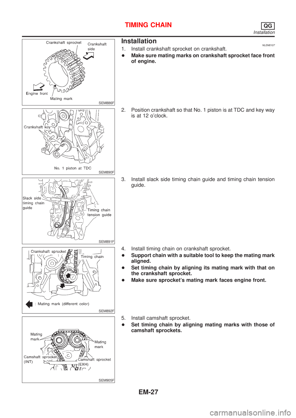
InstallationNLEM01071. Install crankshaft sprocket on crankshaft.
+Make sure mating marks on crankshaft sprocket face front
of engine.
SEM890F
2. Position crankshaft so that No. 1 piston is at TDC and key way
is at 12 o'clock.
SEM891F
3. Install slack side timing chain guide and timing chain tension
guide.
SEM892F
4. Install timing chain on crankshaft sprocket.
+Support chain with a suitable tool to keep the mating mark
aligned.
+Set timing chain by aligning its mating mark with that on
the crankshaft sprocket.
+Make sure sprocket's mating mark faces engine front.
SEM905F
5. Install camshaft sprocket.
+Set timing chain by aligning mating marks with those of
camshaft sprockets.
TIMING CHAINQG
Installation
EM-27
Page 2357 of 3051
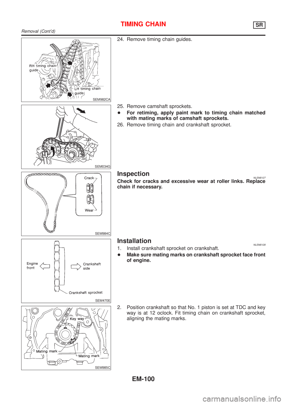
SEM982CA
24. Remove timing chain guides.
SEM034G
25. Remove camshaft sprockets.
+For retiming, apply paint mark to timing chain matched
with mating marks of camshaft sprockets.
26. Remove timing chain and crankshaft sprocket.
SEM984C
InspectionNLEM0127Check for cracks and excessive wear at roller links. Replace
chain if necessary.
SEM470E
InstallationNLEM01281. Install crankshaft sprocket on crankshaft.
+Make sure mating marks on crankshaft sprocket face front
of engine.
SEM985C
2. Position crankshaft so that No. 1 piston is set at TDC and key
way is at 12 oclock. Fit timing chain on crankshaft sprocket,
aligning the mating marks.
TIMING CHAINSR
Removal (Cont'd)
EM-100
Page 2400 of 3051
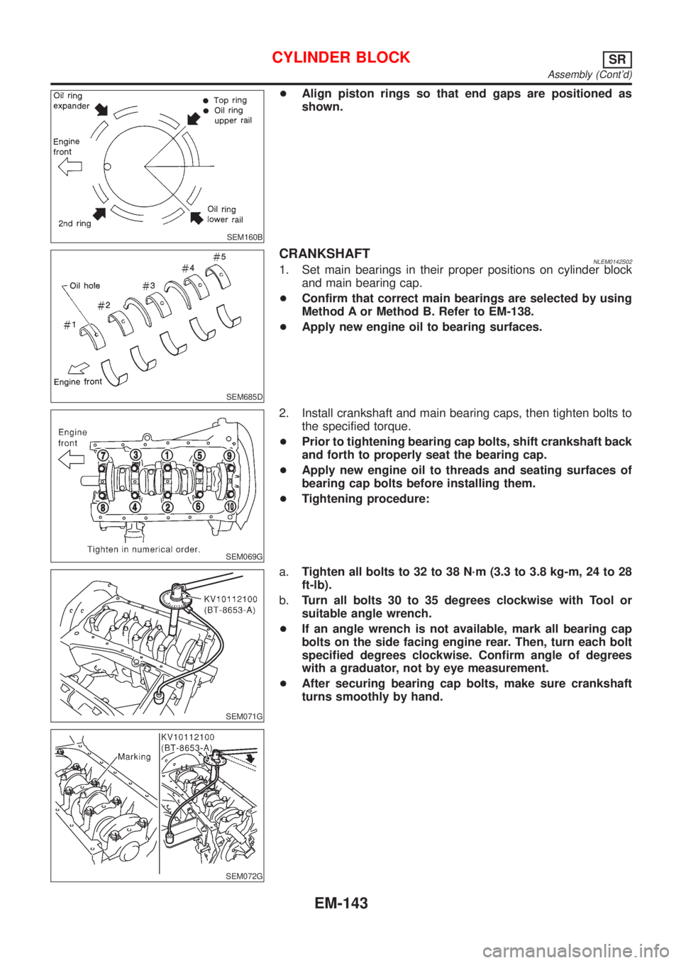
SEM160B
+Align piston rings so that end gaps are positioned as
shown.
SEM685D
CRANKSHAFTNLEM0142S021. Set main bearings in their proper positions on cylinder block
and main bearing cap.
+Confirm that correct main bearings are selected by using
Method A or Method B. Refer to EM-138.
+Apply new engine oil to bearing surfaces.
SEM069G
2. Install crankshaft and main bearing caps, then tighten bolts to
the specified torque.
+Prior to tightening bearing cap bolts, shift crankshaft back
and forth to properly seat the bearing cap.
+Apply new engine oil to threads and seating surfaces of
bearing cap bolts before installing them.
+Tightening procedure:
SEM071G
SEM072G
a.Tighten all bolts to 32 to 38 N´m (3.3 to 3.8 kg-m, 24 to 28
ft-lb).
b.Turn all bolts 30 to 35 degrees clockwise with Tool or
suitable angle wrench.
+If an angle wrench is not available, mark all bearing cap
bolts on the side facing engine rear. Then, turn each bolt
specified degrees clockwise. Confirm angle of degrees
with a graduator, not by eye measurement.
+After securing bearing cap bolts, make sure crankshaft
turns smoothly by hand.
CYLINDER BLOCKSR
Assembly (Cont'd)
EM-143