2001 NISSAN ALMERA TINO key
[x] Cancel search: keyPage 4 of 3051

CONTROL UNIT (EEPROM).......................................182
Description ...............................................................182
Diagnostic Procedure ..............................................183
TROUBLE DIAGNOSES FOR NON-DETECTABLE
ITEMS...........................................................................184
PNP Switch, Stop Lamp Switch and Throttle
Position Switch ........................................................184
Diagnostic Procedure ..............................................184
Wiring Diagram - AT - NONDTC .............................188
TROUBLE DIAGNOSES FOR SYMPTOMS...............192
SPORT Indicator Lamp Does Not Come On ..........192
A/T SHIFT LOCK SYSTEM.........................................195
Description ...............................................................195
Shift Lock System Electrical Parts Location............195
Wiring Diagram - SHIFT -........................................196
Diagnostic Procedure ..............................................198
KEY INTERLOCK CABLE..........................................202
Components.............................................................202
Removal ...................................................................202
Installation ................................................................203ON-VEHICLE SERVICE..............................................204
Control Cable Adjustment ........................................204
Park/Neutral Position (PNP) Switch Adjustment .....204
Differential Side Oil Seal Replacement ...................204
REMOVAL AND INSTALLATION...............................206
Removal ...................................................................206
Inspection.................................................................206
Installation ................................................................207
Air Breather Hose ....................................................208
CVT Fluid Cooler .....................................................208
Components.............................................................209
SERVICE DATA AND SPECIFICATIONS (SDS).......210
General Specifications .............................................210
Stall Revolution ........................................................210
Line Pressure...........................................................210
Removal and Installation .........................................210
A/T Fluid Temperature Sensor.................................210
Solenoid Valves .......................................................210
Dropping Resistor ....................................................210
CONTENTS(Cont'd)
AT-3
Page 8 of 3051

AAT470A
+When connecting or disconnecting pin connectors into or
from TCM, take care not to damage pin terminals (bend or
break).
Make sure that there are not any bends or breaks on TCM
pin terminal, when connecting pin connectors.
MEF040DA
+Before replacing TCM, perform TCM input/output signal
inspection and make sure whether TCM functions prop-
erly or not. (See page AT-58.)
SAT652J
+After performing each TROUBLE DIAGNOSIS, perform
ªDTC (Diagnostic Trouble Code) CONFIRMATION PROCE-
DUREº.
The DTC should not be displayed in the ªDTC CONFIRMA-
TION PROCEDUREº if the repair is completed.
+It is very important to perform functional tests whenever they
are indicated.
+Extreme care should be taken to avoid damage to O-rings,
seals and gaskets when assembling.
+When the CVT drain plug is removed, only some of the fluid is
drained. Old CVT fluid will remain in torque converter and CVT
fluid cooling system.
Always follow the procedures under ªChanging CVT Fluidº in
the MA section when changing CVT fluid.
Service Notice or PrecautionsNLAT0004FAIL-SAFENLAT0004S01The TCM has an electronic Fail-Safe (limp home mode). This allows the vehicle to be driven even if a major
electrical input/output device circuit is damaged.
Under Fail-Safe, the vehicle always runs even with a shift lever position of ªLº or ªDº. The customer may com-
plain of sluggish or poor acceleration.
When the ignition key is turned ªONº following Fail-Safe operation, SPORT indicator lamp blinks for about 8
seconds. [For ªTCM SELF-DIAGNOSTIC PROCEDURE (No Tools)º, refer to AT-28.]
The blinking of the SPORT indicator lamp for about 8 seconds will appear only once and be cleared. The cus-
tomer may resume normal driving conditions.
Always follow the ªWORK FLOWº (Refer to AT-44).
PRECAUTIONS
Precautions (Cont'd)
AT-7
Page 43 of 3051

DIAGNOSTIC WORKSHEET=NLAT0023S01Information from CustomerNLAT0023S0101KEY POINTS
WHAT..... Vehicle & CVT model
WHEN..... Date, Frequencies
WHERE..... Road conditions
HOW..... Operating conditions, Symptoms
Customer name MR/MS Model & Year VIN
Trans. model Engine Mileage
Incident Date Manuf. Date In Service Date
FrequencyNContinuousNIntermittent ( times a day)
NVehicle does not move. (NAny positionNParticular position)
SymptomsNLockup malfunction
NShift point too high or too low.
NShift shock or slip (NN®DNLockupNAny drive position)
NNoise or vibration
NNo pattern select
NOthers
()
SPORT indicator lamp Blinks for about 8 seconds.
NContinuously litNNot lit
Malfunction indicator (MI)NContinuously litNNot lit
TROUBLE DIAGNOSIS Ð INTRODUCTIONEURO-OBD
Introduction (Cont'd)
AT-42
Page 48 of 3051
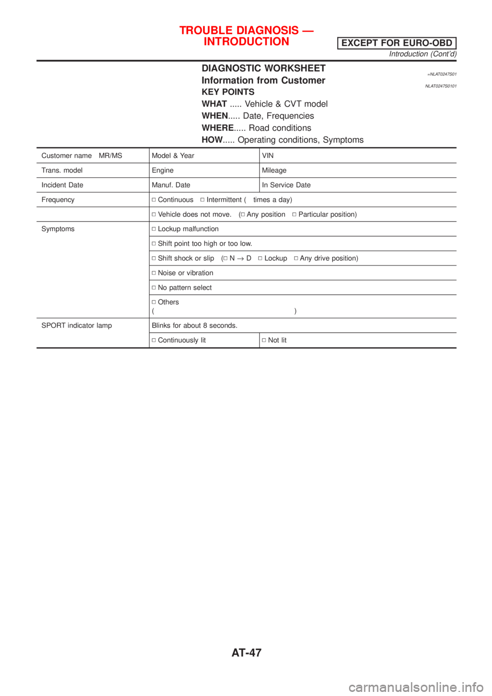
DIAGNOSTIC WORKSHEET=NLAT0247S01Information from CustomerNLAT0247S0101KEY POINTS
WHAT..... Vehicle & CVT model
WHEN..... Date, Frequencies
WHERE..... Road conditions
HOW..... Operating conditions, Symptoms
Customer name MR/MS Model & Year VIN
Trans. model Engine Mileage
Incident Date Manuf. Date In Service Date
FrequencyNContinuousNIntermittent ( times a day)
NVehicle does not move. (NAny positionNParticular position)
SymptomsNLockup malfunction
NShift point too high or too low.
NShift shock or slip (NN®DNLockupNAny drive position)
NNoise or vibration
NNo pattern select
NOthers
()
SPORT indicator lamp Blinks for about 8 seconds.
NContinuously litNNot lit
TROUBLE DIAGNOSIS Ð
INTRODUCTION
EXCEPT FOR EURO-OBD
Introduction (Cont'd)
AT-47
Page 60 of 3051
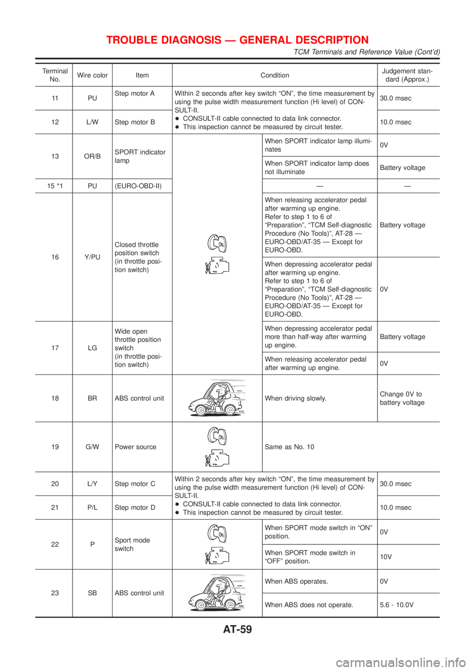
Terminal
No.Wire color Item ConditionJudgement stan-
dard (Approx.)
11 P UStep motor A Within 2 seconds after key switch ªONº, the time measurement by
using the pulse width measurement function (Hi level) of CON-
SULT-II.
+CONSULT-II cable connected to data link connector.
+This inspection cannot be measured by circuit tester.30.0 msec
12 L/W Step motor B10.0 msec
13 OR/BSPORT indicator
lamp
When SPORT indicator lamp illumi-
nates0V
When SPORT indicator lamp does
not illuminateBattery voltage
15 *1 PU (EURO-OBD-II) Ð Ð
16 Y/PUClosed throttle
position switch
(in throttle posi-
tion switch)When releasing accelerator pedal
after warming up engine.
Refer to step 1 to 6 of
ªPreparationº, ªTCM Self-diagnostic
Procedure (No Tools)º, AT-28 Ð
EURO-OBD/AT-35 Ð Except for
EURO-OBD.Battery voltage
When depressing accelerator pedal
after warming up engine.
Refer to step 1 to 6 of
ªPreparationº, ªTCM Self-diagnostic
Procedure (No Tools)º, AT-28 Ð
EURO-OBD/AT-35 Ð Except for
EURO-OBD.0V
17 LGWide open
throttle position
switch
(in throttle posi-
tion switch)When depressing accelerator pedal
more than half-way after warming
up engine.Battery voltage
When releasing accelerator pedal
after warming up engine.0V
18 BR ABS control unit
When driving slowly.Change 0V to
battery voltage
19 G/W Power source
Same as No. 10
20 L/Y Step motor CWithin 2 seconds after key switch ªONº, the time measurement by
using the pulse width measurement function (Hi level) of CON-
SULT-II.
+CONSULT-II cable connected to data link connector.
+This inspection cannot be measured by circuit tester.30.0 msec
21 P/L Step motor D10.0 msec
22 PSport mode
switch
When SPORT mode switch in ªONº
position.0V
When SPORT mode switch in
ªOFFº position.10V
23 SB ABS control unit
When ABS operates. 0V
When ABS does not operate. 5.6 - 10.0V
TROUBLE DIAGNOSIS Ð GENERAL DESCRIPTION
TCM Terminals and Reference Value (Cont'd)
AT-59
Page 113 of 3051
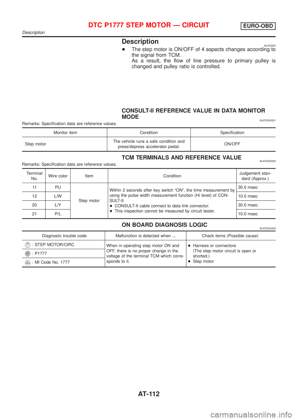
DescriptionNLAT0224+The step motor is ON/OFF of 4 aspects changes according to
the signal from TCM.
As a result, the flow of line pressure to primary pulley is
changed and pulley ratio is controlled.
CONSULT-II REFERENCE VALUE IN DATA MONITOR
MODE
NLAT0224S01Remarks: Specification data are reference values.
Monitor item Condition Specification
Step motorThe vehicle runs a safe condition and
press/depress accelerator pedal.ON/OFF
TCM TERMINALS AND REFERENCE VALUENLAT0224S02Remarks: Specification data are reference values.
Terminal
No.Wire color Item ConditionJudgement stan-
dard (Approx.)
11 P U
Step motorWithin 2 seconds after key switch ªONº, the time measurement by
using the pulse width measurement function (Hi level) of CON-
SULT-II.
+CONSULT-II cable connect to data link connector.
+This inspection cannot be measured by circuit tester.30.0 msec
12 L/W10.0 msec
20 L/Y30.0 msec
21 P/L10.0 msec
ON BOARD DIAGNOSIS LOGICNLAT0224S03
Diagnostic trouble code Malfunction is detected when ... Check items (Possible cause)
: STEP MOTOR/CIRC
When in operating step motor ON and
OFF, there is no proper change in the
voltage of the terminal TCM which corre-
sponds to it.+Harness or connectors
(The step motor circuit is open or
shorted.)
+Step motor
: P1777
: MI Code No. 1777
DTC P1777 STEP MOTOR Ð CIRCUITEURO-OBD
Description
AT-112
Page 147 of 3051
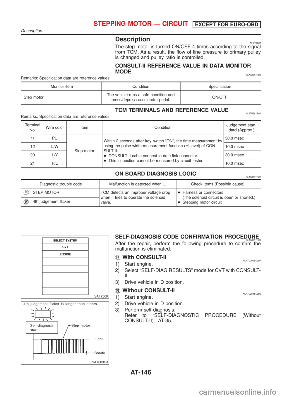
DescriptionNLAT0261The step motor is turned ON/OFF 4 times according to the signal
from TCM. As a result, the flow of line pressure to primary pulley
is changed and pulley ratio is controlled.
CONSULT-II REFERENCE VALUE IN DATA MONITOR
MODE
NLAT0261S05Remarks: Specification data are reference values.
Monitor item Condition Specification
Step motorThe vehicle runs a safe condition and
press/depress accelerator pedal.ON/OFF
TCM TERMINALS AND REFERENCE VALUENLAT0261S01Remarks: Specification data are reference values.
Terminal
No.Wire color Item ConditionJudgement stan-
dard (Approx.)
11 P U
Step motorWithin 2 seconds after key switch ªONº, the time measurement by
using the pulse width measurement function (Hi level) of CON-
SULT-II.
+CONSULT-II cable connect to data link connector.
+This inspection cannot be measured by circuit tester.30.0 msec
12 L/W10.0 msec
20 L/Y30.0 msec
21 P/L10.0 msec
ON BOARD DIAGNOSIS LOGICNLAT0261S02
Diagnostic trouble code Malfunction is detected when ... Check items (Possible cause)
: STEP MOTOR TCM detects an improper voltage drop
when it tries to operate the solenoid
valve.+Harness or connectors
(The solenoid circuit is open or shorted.)
+Stepping motor circuit
: 4th judgement flicker
SAT250K
SAT809HA
SELF-DIAGNOSIS CODE CONFIRMATION PROCEDURENLAT0261S03After the repair, perform the following procedure to confirm the
malfunction is eliminated.
With CONSULT-IINLAT0261S03011) Start engine.
2) Select ªSELF-DIAG RESULTSº mode for CVT with CONSULT-
II.
3) Drive vehicle in D position.
Without CONSULT-IINLAT0261S03021) Start engine.
2) Drive vehicle in D position.
3) Perform self-diagnosis.
Refer to ªSELF-DIAGNOSTIC PROCEDURE (Without
CONSULT-II)º, AT-35.
STEPPING MOTOR Ð CIRCUITEXCEPT FOR EURO-OBD
Description
AT-146
Page 196 of 3051
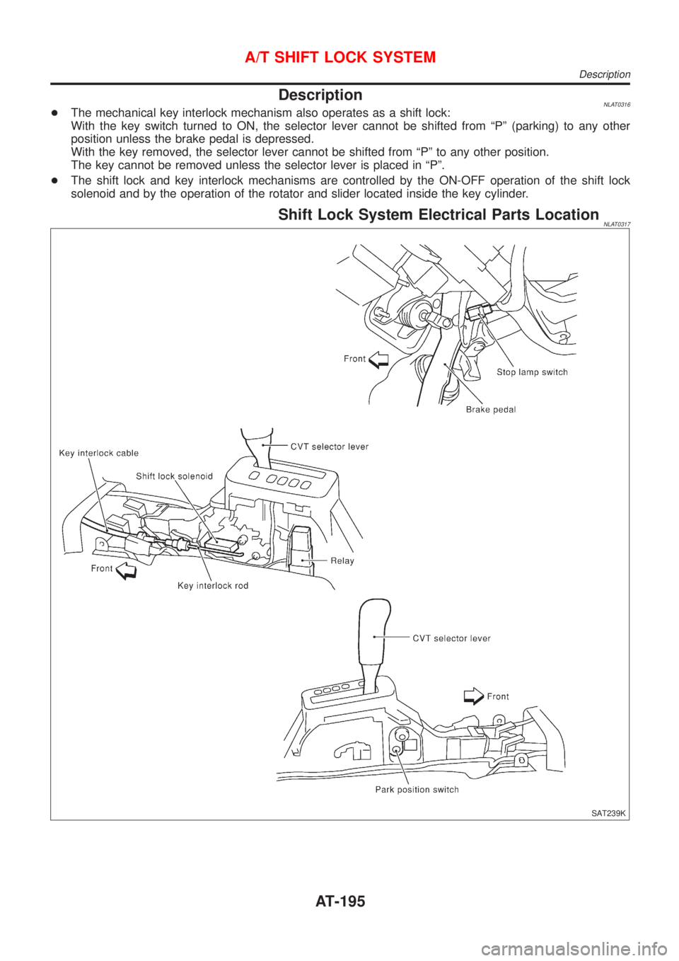
DescriptionNLAT0316+The mechanical key interlock mechanism also operates as a shift lock:
With the key switch turned to ON, the selector lever cannot be shifted from ªPº (parking) to any other
position unless the brake pedal is depressed.
With the key removed, the selector lever cannot be shifted from ªPº to any other position.
The key cannot be removed unless the selector lever is placed in ªPº.
+The shift lock and key interlock mechanisms are controlled by the ON-OFF operation of the shift lock
solenoid and by the operation of the rotator and slider located inside the key cylinder.
Shift Lock System Electrical Parts LocationNLAT0317
SAT239K
A/T SHIFT LOCK SYSTEM
Description
AT-195