Page 1069 of 3051

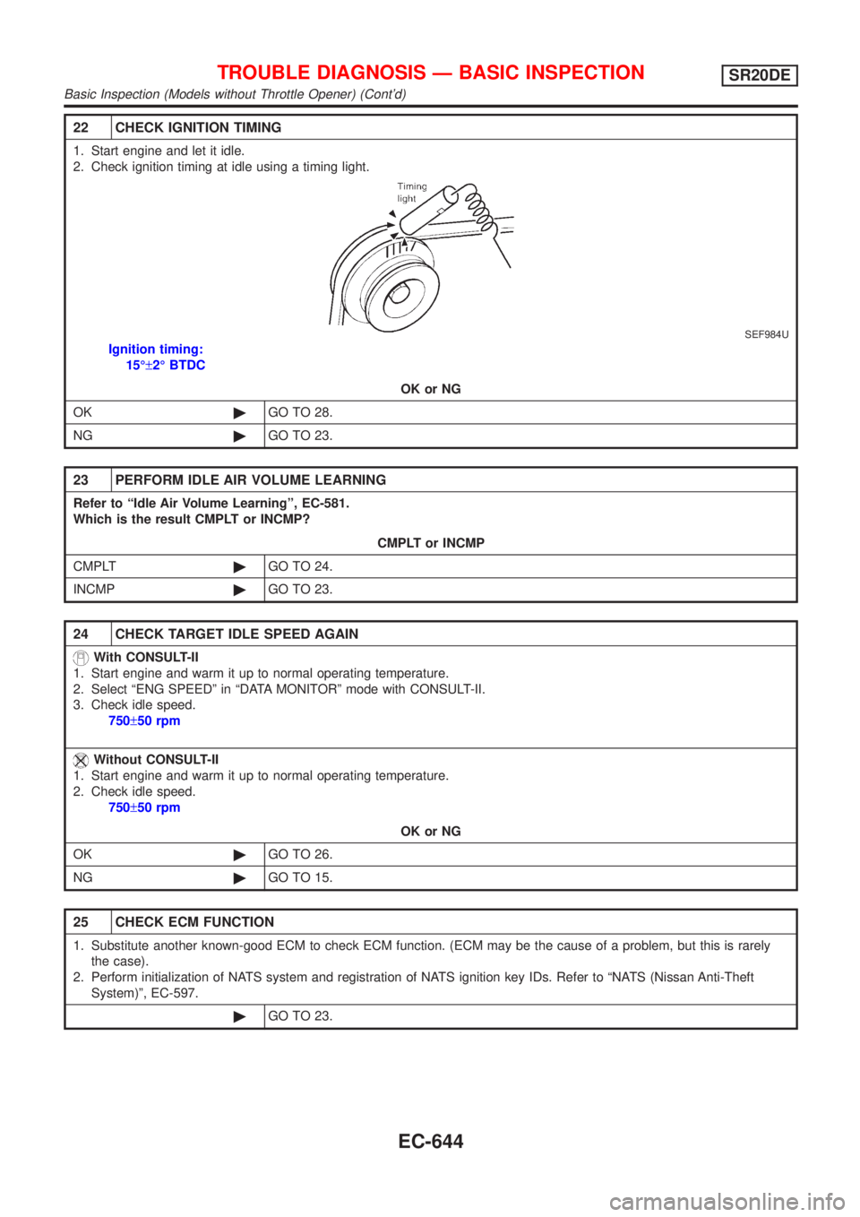
22 CHECK IGNITION TIMING
1. Start engine and let it idle.
2. Check ignition timing at idle using a timing light.
SEF984U
Ignition timing:
15ɱ2É BTDC
OK or NG
OK©GO TO 28.
NG©GO TO 23.
23 PERFORM IDLE AIR VOLUME LEARNING
Refer to ªIdle Air Volume Learningº, EC-581.
Which is the result CMPLT or INCMP?
CMPLT or INCMP
CMPLT©GO TO 24.
INCMP©GO TO 23.
24 CHECK TARGET IDLE SPEED AGAIN
With CONSULT-II
1. Start engine and warm it up to normal operating temperature.
2. Select ªENG SPEEDº in ªDATA MONITORº mode with CONSULT-II.
3. Check idle speed.
750±50 rpm
Without CONSULT-II
1. Start engine and warm it up to normal operating temperature.
2. Check idle speed.
750±50 rpm
OK or NG
OK©GO TO 26.
NG©GO TO 15.
25 CHECK ECM FUNCTION
1. Substitute another known-good ECM to check ECM function. (ECM may be the cause of a problem, but this is rarely
the case).
2. Perform initialization of NATS system and registration of NATS ignition key IDs. Refer to ªNATS (Nissan Anti-Theft
System)º, EC-597.
©GO TO 23.
TROUBLE DIAGNOSIS Ð BASIC INSPECTIONSR20DE
Basic Inspection (Models without Throttle Opener) (Cont'd)
EC-644
Page 1306 of 3051
Diagnostic Procedure=NLEC1599
1 INSPECTION START
With CONSULT-II
1. Turn ignition switch ªONº.
2. Select ªSELF DIAG RESULTSº mode with CONSULT-II.
3. Touch ªERASEº.
4. Perform ªDTC Confirmation Procedureº.
See EC-880.
5. Is the 1st trip DTC P0605 displayed again?
With GST
1. Turn ignition switch ªONº.
2. Select MODE 4 with GST.
3. Touch ªERASEº.
4. Perform ªDTC Confirmation Procedureº.
See EC-880.
5. Is the 1st trip DTC P0605 displayed again?
YesorNo
Ye s©GO TO 2.
No©INSPECTION END
2 REPLACE ECM
1. Replace ECM.
2. Perform initialization of NATS (NISSAN ANTI-THEFT SYSTEM) system and registration of all NATS ignition key IDs.
Refer to ªNATS (NISSAN ANTI-THEFT SYSTEM)º, EC-597.
3. Perform ªIdle Air Volume Learningº, EC-581.
Is the result CMPLT or INCMP?
CMPLT or INCMP
CMPLT©INSPECTION END
INCMP©Follow the construction of ªIdle Air Volume Learningº.
DTC P0605 ECMSR20DE
Diagnostic Procedure
EC-881
Page 1523 of 3051
On Board Diagnostic System FunctionNLEC0628S01The on board diagnostic system has the following three functions.
Diagnostic Test
ModeKEY and ENG.
StatusFunction Explanation of Function
Mode I Ignition switch in
ON position
Engine stopped
BULB CHECK This function checks the MI bulb for damage (blown,
open circuit, etc.).
If the MI does not come on, check MI circuit. (See
EC-1303.)
Engine running
MALFUNCTION
WARNINGThis is a usual driving condition. When ECM detects a
malfunction, the MI will light up to inform the driver that
a malfunction has been detected.
Mode II Ignition switch in
ON position
Engine stopped
SELF-DIAGNOSTIC RESULTS This function allows DTCs to be read.
ON BOARD DIAGNOSTIC SYSTEM DESCRIPTIONYD22DDTI
Malfunction Indicator (MI) (Cont'd)
EC-1098
Page 1847 of 3051
![NISSAN ALMERA TINO 2001 Service Repair Manual System DescriptionNLEL0435POWER SUPPLY AND GROUNDNLEL0435S01Power is supplied at all times:
+through 15A fuse [No. 5, located in the fuse block (J/B)]
+to time control unit terminal 9,
+through 10A fu NISSAN ALMERA TINO 2001 Service Repair Manual System DescriptionNLEL0435POWER SUPPLY AND GROUNDNLEL0435S01Power is supplied at all times:
+through 15A fuse [No. 5, located in the fuse block (J/B)]
+to time control unit terminal 9,
+through 10A fu](/manual-img/5/57352/w960_57352-1846.png)
System DescriptionNLEL0435POWER SUPPLY AND GROUNDNLEL0435S01Power is supplied at all times:
+through 15A fuse [No. 5, located in the fuse block (J/B)]
+to time control unit terminal 9,
+through 10A fuse [No. 12, located in the fuse block (J/B)]
+to key switch terminal 1 and
+through 10A fuse [No. 13, located in the fuse block (J/B)]
+to spot lamp terminal 1, and
+to interior room lamp terminal 1.
When the key is removed from ignition key cylinder, power is interrupted:
+through key switch terminal 2
+to time control unit terminal 22.
With the ignition key switch in the ON or START position, power is supplied:
+through 10A fuse [No. 10, located in the fuse block (J/B)]
+to time control unit terminal 1.
Ground is supplied:
+through body grounds terminals M28 and M48
+to time control unit terminal 16
When the driver side door is opened, ground is supplied:
+through body grounds B24 and B30
+to door switch driver side terminal 3
+from door switch driver side terminal 2
+to time control unit terminal 6.
When any door is opened, ground is supplied:
+through case ground of each door switch
+to each door switch terminal 1
+to time control unit terminal 7.
When the driver side door is unlocked, the time control unit receives a ground signal:
+through body grounds terminals M28 and M48
+to door unlock sensor terminal 2 (LHD models) or 4 (RHD models)
+from door unlock sensor terminal 5 (LHD models) or 2 (RHD models)
+to time control unit terminal 35.
When a signal, or combination of signals is received by the time control unit, ground is supplied:
+through time control unit terminal 12
+to spot lamp terminal 2, and
+to interior room lamp terminal 2.
With power and ground supplied, the interior room lamp and spot lamp illuminates when the lamp switch is
in ªDOORº position.
SWITCH OPERATIONNLEL0435S02When interior room lamp switch is in ªONº position, ground is supplied:
+through case grounds of interior room lamp
+to interior room lamp.
With power and ground supplied, the interior room lamp illuminates.
INTERIOR ROOM LAMP TIMER OPERATIONNLEL0435S03When interior room lamp switch is in the ªDOORº position, the time control unit keeps the interior room lamp
illuminated for about 30 seconds when:
+unlock signal is supplied from driver's door unlock sensor while all doors are closed
+key is removed from ignition key cylinder while all doors are closed
+driver's door is opened and then closed
INTERIOR ROOM LAMP
System Description
EL-116
Page 1856 of 3051
7 CHECK DOOR SWITCHES
1. Disconnect door switch harness connector.
2. Check continuity between door switch terminal 1 and ground.
NEL652
OK or NG
OK©Check the following.
+Door switch ground condition
+Harness for open or short between time control unit and door switch
NG©Replace door switch.
8 CHECK KEY SWITCH INPUT SIGNAL
Check voltage between time control unit harness connector terminal 22 and ground.
NEL653
OK or NG
OK©Replace time control unit.
NG©GO TO 9.
INTERIOR ROOM LAMP
Trouble Diagnoses (Cont'd)
EL-125
Page 1857 of 3051
9 CHECK KEY SWITCH (INSERT)
Check continuity between terminals 1 and 2.
NEL787
OK or NG
OK©Check the following.
+10A fuse [No. 12, located in fuse block (J/B)]
+Harness for open or short between key switch and fuse
+Harness for open or short between time control unit and key switch
NG©Replace key switch.
DIAGNOSTIC PROCEDURE 2NLEL0437S02SYMPTOM: Interior lamp timer does not cancel properly.
1 CHECK IGNITION ON SIGNAL
Check voltage between time control unit harness connector terminal 1 and ground.
NEL646
OK or NG
OK©GO TO 2.
NG©Check the following.
+10A fuse [No. 10, located in fuse block (J/B)]
+Harness for open or short between time control unit and fuse
INTERIOR ROOM LAMP
Trouble Diagnoses (Cont'd)
EL-126
Page 1896 of 3051

Component Parts and Harness Connector
Location
NLEL0452For details, refer to ªELECTRICAL UNIT LOCATIONº (EL-442) and ªHARNESS LAYOUTº (EL-452).
System DescriptionNLEL0453The warning chime is controlled by the time control unit.
The warning chime is located in the time control unit.
Power is supplied at all times
+through 15A fuse [No. 5, located in fuse block (J/B)]
+to time control unit terminal 9.
+through 10A fuse [No. 12, located in the fuse block (J/B)]
+to key switch terminal 1.
+through 10A fuse (No. 38, located in the fuse and fusible link box)
+to lighting switch terminal 11.
With the ignition switch in the ON or START position, power is supplied
+through 10A fuse [No. 10, located in the fuse block (J/B)]
+to time control unit terminal 1.
Ground is supplied to time control unit terminal 16 through body grounds M28 and M48.
When a signal, or combination of signals, is received by the time control unit, the warning chime will sound.
IGNITION KEY WARNING CHIMENLEL0453S01With the key in the ignition switch in the OFF position, the driver's door open and driver's door locked, the
warning chime will sound. Power is supplied
+from key switch terminal 2
+to time control unit terminal 22.
Ground is supplied
+from body grounds B24 and B30
+through front door switch (driver side) terminals 3 and 2
+to time control unit terminal 6, and
Ground is interrupted,
+from body grounds M28 and M48
+to time control unit terminal 35
LIGHT WARNING CHIMENLEL0453S02With ignition switch OFF, driver's door open, and lighting switch in 1ST or 2ND position, warning chime will
sound. Power is supplied.
+from lighting switch terminal 12
+to time control unit terminal 10
Ground is supplied
+from front door switch (driver side) terminal 2
+to time control unit terminal 6.
Front door switch (driver side) terminal 3 is grounded through body grounds B24 and B30.
TRAILER DIRECTION INDICATOR WARNING CHIMENLEL0453S04This warning chime will be sounded while the direction indicator (turn signal lamp) is in operation with towing
the trailer.
This is an audible feedback (warning chime) to the driver.
If no audible feedback is heard while towing the trailer and operating the turn signal, this indicates the bulb
failure of the trailer.
Time control unit will detect the additional electrical load of a turn signal lamp for trailer automatically. Then
the chime will be sounded by the time control unit internally with the operation of the turn signal.
WARNING CHIME
Component Parts and Harness Connector Location
EL-165
Page 1901 of 3051
Trouble DiagnosesNLEL0455SYMPTOM CHARTNLEL0455S01
REFERENCE PAGE (EL- ) 170 171 172 173 174
SYMPTOM
POWER SUPPLY AND
GROUND CIRCUIT CHECK
DIAGNOSTIC PROCEDURE 1
(LIGHTING SWITCH INPUT
SIGNAL CHECK)
DIAGNOSTIC PROCEDURE 2
(KEY SWITCH INSERT
SIGNAL CHECK)
DIAGNOSTIC PROCEDURE 3
(DOOR UNLOCK SENSOR CHECK)
DIAGNOSTIC PROCEDURE 4
Light warning chime does not acti-
vate.XX X
Ignition key warning chime does not
activate.XXXX
All warning chimes do not activate. XX
POWER SUPPLY AND GROUND CIRCUIT CHECKNLEL0455S02Power Supply Circuit CheckNLEL0455S0201
NEL665
Ground Circuit CheckNLEL0455S0202
NEL666
WARNING CHIME
Trouble Diagnoses
EL-170