2001 NISSAN ALMERA TINO remote control
[x] Cancel search: remote controlPage 1733 of 3051
Electrical Components Inspection ...........................164
WARNING CHIME.......................................................165
Component Parts and Harness Connector
Location ...................................................................165
System Description ..................................................165
Wiring Diagram - CHIME - ......................................166
Trouble Diagnoses...................................................170
FRONT WIPER AND WASHER..................................176
System Description ..................................................176
Wiring Diagram - WIPER - ......................................178
Removal and Installation .........................................182
Washer Nozzle Adjustment .....................................183
Washer Tube Layout ...............................................183
REAR WIPER AND WASHER....................................184
Wiring Diagram - WIP/R -........................................184
Removal and Installation .........................................188
Washer Nozzle Adjustment .....................................188
Washer Tube Layout ...............................................189
HEADLAMP WASHER................................................190
Wiring Diagram - HLC - ...........................................190
Washer Tube Layout ...............................................192
HORN...........................................................................193
Wiring Diagram - HORN - .......................................193
CIGARETTE LIGHTER................................................195
Wiring Diagram - CIGAR -.......................................195
CLOCK.........................................................................196
Wiring Diagram - CLOCK -......................................196
REAR WINDOW DEFOGGER.....................................198
System Description ..................................................198
Wiring Diagram - DEF - ...........................................199
Trouble Diagnoses...................................................203
Electrical Components Inspection ...........................205
Filament Check ........................................................206
Filament Repair .......................................................207
AUDIO..........................................................................208
System Description ..................................................208
Schematic ................................................................210
Wiring Diagram - AUDIO - .......................................212
Trouble Diagnoses...................................................230
Inspection.................................................................232
AUDIO ANTENNA.......................................................233
Location of Antenna .................................................233
Antenna Rod Replacement .....................................233
HEATED SEAT............................................................234
Wiring Diagram - H/SEAT - .....................................234
POWER SUNROOF.....................................................238
Wiring Diagram - SROOF - .....................................238
Trouble Diagnoses...................................................240
DOOR MIRROR...........................................................241
Wiring Diagram - MIRROR - ...................................241
POWER WINDOW.......................................................245
System Description ..................................................245Schematic ................................................................247
Wiring Diagram - WINDOW - ..................................248
Trouble Diagnoses...................................................256
POWER DOOR LOCK.................................................257
Component Parts and Harness Connector
Location/LHD Models ..............................................257
System Description/LHD Models .............................257
Schematic/LHD Models ...........................................258
Wiring Diagram - D/LOCK -/LHD Models................260
Trouble Diagnoses/LHD Models..............................272
POWER DOOR LOCK - SUPER LOCK -...................281
System Description/RHD Models ............................281
Schematic/RHD Models...........................................284
Wiring Diagram - S/LOCK -/RHD Models ...............286
Trouble Diagnoses/RHD Models .............................300
MULTI-REMOTE CONTROL SYSTEM.......................314
System Description ..................................................314
Wiring Diagram - MULTI - .......................................315
Trouble Diagnoses...................................................319
ID Code Entry Procedure ........................................324
Remote Controller Battery Replacement.................325
TIME CONTROL UNIT................................................326
Description ...............................................................326
Trouble Diagnoses...................................................327
Schematic ................................................................330
NATS (NISSAN ANTI-THEFT SYSTEM).....................334
Component Parts and Harness Connector
Location ...................................................................334
System Description ..................................................334
System Composition ................................................335
Schematic ................................................................336
Wiring Diagram - NATS -.........................................338
CONSULT-II .............................................................346
Trouble Diagnoses...................................................349
How to Replace NATS IMMU ..................................369
NAVIGATION SYSTEM...............................................370
Precautions ..............................................................370
Component Parts Location ......................................370
System Description ..................................................370
Schematic ................................................................379
Wiring Diagram - NAVI - ..........................................381
Self-diagnosis Mode ................................................401
Confirmation/Adjustment Mode ...............................404
Control Panel Mode .................................................416
Guide Volume Setting ..............................................423
Anti-theft System .....................................................424
CONSULT-II .............................................................425
Trouble Diagnoses...................................................426
This Condition Is Not Abnormal...............................432
Program Loading .....................................................441
ELECTRICAL UNITS LOCATION...............................442
Engine Compartment ...............................................442
CONTENTS(Cont'd)
EL-2
Page 1832 of 3051
![NISSAN ALMERA TINO 2001 Service Repair Manual System DescriptionNLEL0430TURN SIGNAL OPERATIONNLEL0430S01Power is supplied at all times
+through 15A fuse [No. 5, located in fuse block (J/B)]
+to time control unit terminal 9
With the ignition switc NISSAN ALMERA TINO 2001 Service Repair Manual System DescriptionNLEL0430TURN SIGNAL OPERATIONNLEL0430S01Power is supplied at all times
+through 15A fuse [No. 5, located in fuse block (J/B)]
+to time control unit terminal 9
With the ignition switc](/manual-img/5/57352/w960_57352-1831.png)
System DescriptionNLEL0430TURN SIGNAL OPERATIONNLEL0430S01Power is supplied at all times
+through 15A fuse [No. 5, located in fuse block (J/B)]
+to time control unit terminal 9
With the ignition switch in the ON or START position, power is supplied
+through 10A fuse [No. 10, located in fuse block (J/B)]
+to time control unit terminal 1
Ground is supplied to time control unit terminal 16 through body grounds M28 and M48.
LH TurnNLEL0430S0101When the turn signal switch is moved to the L position, ground is supplied from body grounds E24 and E73
to
+time control unit terminal 2
+through turn signal switch terminals 3 and 1
With ground is supplied, time control unit controls the flashing of the LH turn signal lamps.
RH TurnNLEL0430S0102When the turn signal switch is moved to the R position, ground is supplied from body grounds E30 and E73
to
+time control unit terminal 4
+through turn signal switch terminals 2 and 1
With ground is supplied, time control unit controls the flashing of the RH turn signal lamps.
HAZARD LAMP OPERATIONNLEL0430S02Power is supplied at all times
+through 15A fuse [No. 5, located in fuse block (J/B)]
+to time control unit terminal 9
Ground is supplied to time control unit terminal 16 through body grounds M28 and M48.
With the hazard switch in the ON position, ground is supplied from body grounds M28 and M48 to
+time control unit terminal 5
+through hazard switch terminals 6 and 4
With ground is supplied, time control unit controls the flashing of the hazard warning lamps.
HAZARD REMINDER OPERATION FOR MULTI-REMOTE CONTROL SYSTEMNLEL0430S04When the doors are locked or unlocked by multi-remote controller, time control unit controls turn lamps haz-
ard reminder flashes as follows.
+Locked operation: Flash once
+Unlock operation: Flash twice
TURN SIGNAL AND HAZARD WARNING LAMPS
System Description
EL-101
Page 1988 of 3051
Component Parts and Harness Connector
Location/LHD Models
NLEL0526For details, refer to ªELECTRICAL UNIT LOCATIONº (EL-442) and ªHARNESS LAYOUTº (EL-452).
System Description/LHD ModelsNLEL0502OPERATIONNLEL0502S02Power door lock/unlock operation by door key cylinder
+With the key inserted into front door key cylinder, turning it to LOCK will lock all doors.
+With the key inserted into front door key cylinder, turning it to UNLOCK will unlock all doors.
Power door lock/unlock operation by multi-remote controller (If equipped)
+Pressing multi-remote controller LOCK button will lock all doors.
+Pressing multi-remote controller UNLOCK button once will unlock driver door. Then, if an unlock signal is
sent from the remote controller again within 5 seconds, all other doors will be unlocked.
Power door lock/unlock operation by lock/unlock switch
+With lock/unlock switch on driver door trim setting to LOCK will lock all doors.
+With lock/unlock switch on driver door trim setting to UNLOCK will unlock all doors.
Key reminder system
+If the ignition key is in the ignition key cylinder and driver door is open, setting lock/unlock switch, lock
knob, key or multi-remote controller to ªLOCKº locks the door once but then immediately unlocks all doors.
(signal from door unlock sensor driver side)
POWER DOOR LOCK
Component Parts and Harness Connector Location/LHD Models
EL-257
Page 2012 of 3051
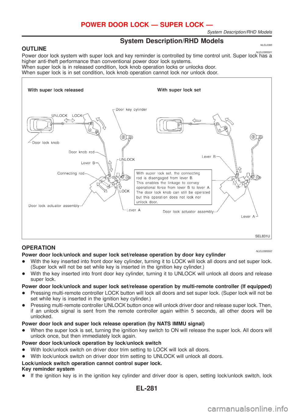
System Description/RHD ModelsNLEL0395OUTLINENLEL0395S01Power door lock system with super lock and key reminder is controlled by time control unit. Super lock has a
higher anti-theft performance than conventional power door lock systems.
When super lock is in released condition, lock knob operation locks or unlocks door.
When super lock is in set condition, lock knob operation cannot lock nor unlock door.
SEL831U
OPERATIONNLEL0395S02Power door lock/unlock and super lock set/release operation by door key cylinder
+With the key inserted into front door key cylinder, turning it to LOCK will lock all doors and set super lock.
(Super lock will not be set while key is inserted in the ignition key cylinder.)
+With the key inserted into front door key cylinder, turning it to UNLOCK will unlock all doors and release
super lock.
Power door lock/unlock and super lock set/release operation by multi-remote controller (If equipped)
+Pressing multi-remote controller LOCK button will lock all doors and set super lock. (Super lock will not be
set while key is inserted in the ignition key cylinder.)
+Pressing multi-remote controller UNLOCK button once will unlock driver door and release super lock. Then,
if an unlock signal is sent from the remote controller again within 5 seconds, all other doors will be
unlocked.
Power door lock and super lock release operation (by NATS IMMU signal)
+When the super lock is set, turning the ignition key switch to ON will release the super lock. All doors will
unlock once, but then immediately lock again.
Power door lock/unlock operation by lock/unlock switch
+With lock/unlock switch on driver door trim setting to LOCK will lock all doors.
+With lock/unlock switch on driver door trim setting to UNLOCK will unlock all doors.
Lock/unlock switch operation cannot control super lock.
Key reminder system
+If the ignition key is in the ignition key cylinder and driver door is open, setting lock/unlock switch, lock
POWER DOOR LOCK Ð SUPER LOCK Ð
System Description/RHD Models
EL-281
Page 2013 of 3051
knob, key or multi-remote controller to ªLOCKº locks the door once but then immediately unlocks all doors.
(signal from door unlock sensor driver side)
System initialization
+System initialization is required when battery cables are reconnected. Conduct the following to release
super lock once;
Ð insert the key into the ignition key cylinder and turn it to ON.
Ð LOCK/UNLOCK operation using door key cylinder or multi-remote controller.
POWER DOOR LOCK Ð SUPER LOCK Ð
System Description/RHD Models (Cont'd)
EL-282
Page 2032 of 3051
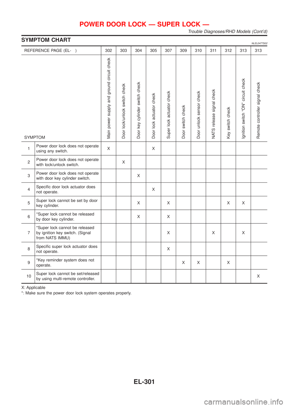
SYMPTOM CHARTNLEL0477S02
REFERENCE PAGE (EL- ) 302 303 304 305 307 309 310 311 312 313 313
SYMPTOM
Main power supply and ground circuit check
Door lock/unlock switch check
Door key cylinder switch check
Door lock actuator check
Super lock actuator check
Door switch check
Door unlock sensor check
NATS release signal check
Key switch check
Ignition switch ªONº circuit check
Remote controller signal check
1Power door lock does not operate
using any switch.XX
2Power door lock does not operate
with lock/unlock switch.X
3Power door lock does not operate
with door key cylinder switch.X
4Specific door lock actuator does
not operate.X
5Super lock cannot be set by door
key cylinder.XX XX
6*Super lock cannot be released
by door key cylinder.XX
7*Super lock cannot be released
by ignition key switch. (Signal
from NATS IMMU)XXX
8Specific super lock actuator does
not operate.X
9*Key reminder system does not
operate.XX X
10Super lock cannot be set/released
by using multi-remote controller.X
X: Applicable
*: Make sure the power door lock system operates properly.
POWER DOOR LOCK Ð SUPER LOCK Ð
Trouble Diagnoses/RHD Models (Cont'd)
EL-301
Page 2044 of 3051
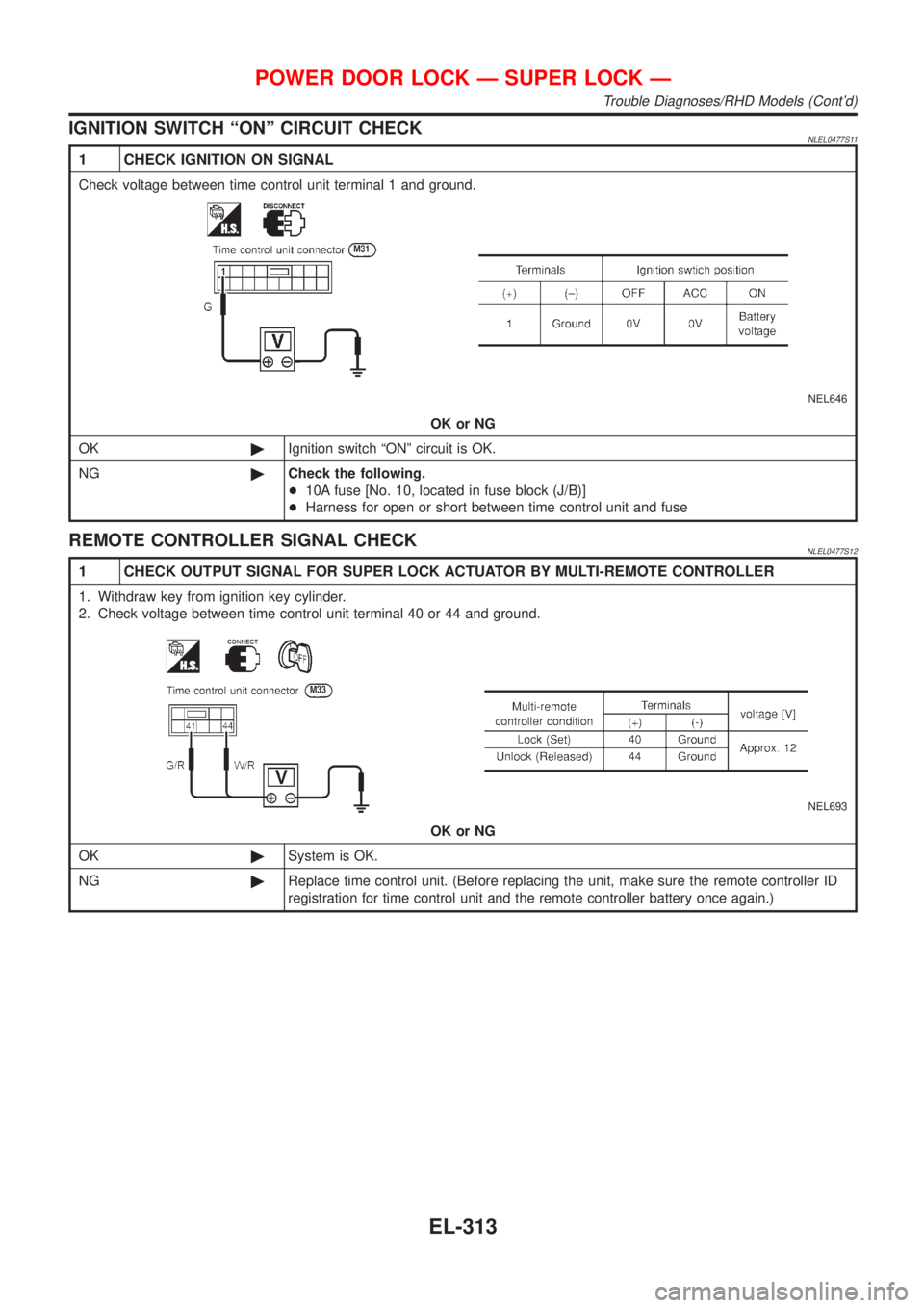
IGNITION SWITCH ªONº CIRCUIT CHECKNLEL0477S11
1 CHECK IGNITION ON SIGNAL
Check voltage between time control unit terminal 1 and ground.
NEL646
OK or NG
OK©Ignition switch ªONº circuit is OK.
NG©Check the following.
+10A fuse [No. 10, located in fuse block (J/B)]
+Harness for open or short between time control unit and fuse
REMOTE CONTROLLER SIGNAL CHECKNLEL0477S12
1 CHECK OUTPUT SIGNAL FOR SUPER LOCK ACTUATOR BY MULTI-REMOTE CONTROLLER
1. Withdraw key from ignition key cylinder.
2. Check voltage between time control unit terminal 40 or 44 and ground.
NEL693
OK or NG
OK©System is OK.
NG©Replace time control unit. (Before replacing the unit, make sure the remote controller ID
registration for time control unit and the remote controller battery once again.)
POWER DOOR LOCK Ð SUPER LOCK Ð
Trouble Diagnoses/RHD Models (Cont'd)
EL-313
Page 2045 of 3051
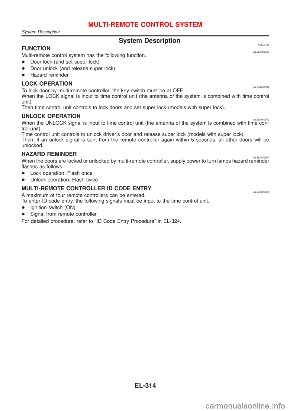
System DescriptionNLEL0480FUNCTIONNLEL0480S01Multi-remote control system has the following function.
+Door lock (and set super lock)
+Door unlock (and release super lock)
+Hazard reminder
LOCK OPERATIONNLEL0480S02To lock door by multi-remote controller, the key switch must be at OFF.
When the LOCK signal is input to time control unit (the antenna of the system is combined with time control
unit)
Then time control unit controls to lock doors and set super lock (models with super lock).
UNLOCK OPERATIONNLEL0480S03When the UNLOCK signal is input to time control unit (the antenna of the system is combined with time con-
trol unit)
Time control unit controls to unlock driver's door and release super lock (models with super lock).
Then, if an unlock signal is sent from the remote controller again within 5 seconds, all other doors will be
unlocked.
HAZARD REMINDERNLEL0480S04When the doors are locked or unlocked by multi-remote controller, supply power to turn lamps hazard reminder
flashes as follows
+Lock operation: Flash once
+Unlock operation: Flash twice
MULTI-REMOTE CONTROLLER ID CODE ENTRYNLEL0480S05A maximum of four remote controllers can be entered.
To enter ID code entry, the following signals must be input to the time control unit.
+Ignition switch (ON)
+Signal from remote controller
For detailed procedure, refer to ªID Code Entry Procedureº in EL-324.
MULTI-REMOTE CONTROL SYSTEM
System Description
EL-314