Page 199 of 3051

Diagnostic ProcedureNLAT0319SYMPTOM 1:
+Selector lever cannot be moved from ªPº position with key
in ON position and brake pedal applied.
+Selector lever can be moved from ªPº position with key in
ON position and brake pedal released.
+Selector lever can be moved from ªPº position when key
is removed from key cylinder.
SYMPTOM 2:
Ignition key cannot be removed when selector lever is set to
ªPº position. It can be removed when selector lever is set to
any position except ªPº.
1 CHECK KEY INTERLOCK CABLE
Check key interlock cable for damage.
OK or NG
OK©GO TO 2.
NG©Repair key interlock cable. Refer to AT-202.
2 CHECK SELECTOR LEVER POSITION
Check selector lever position for damage.
OK or NG
OK©GO TO 3.
NG©Check selector lever. Refer to ªON-VEHICLE SERVICE Ð PNP Switch and Control
Cable Adjustmentº, AT-204.
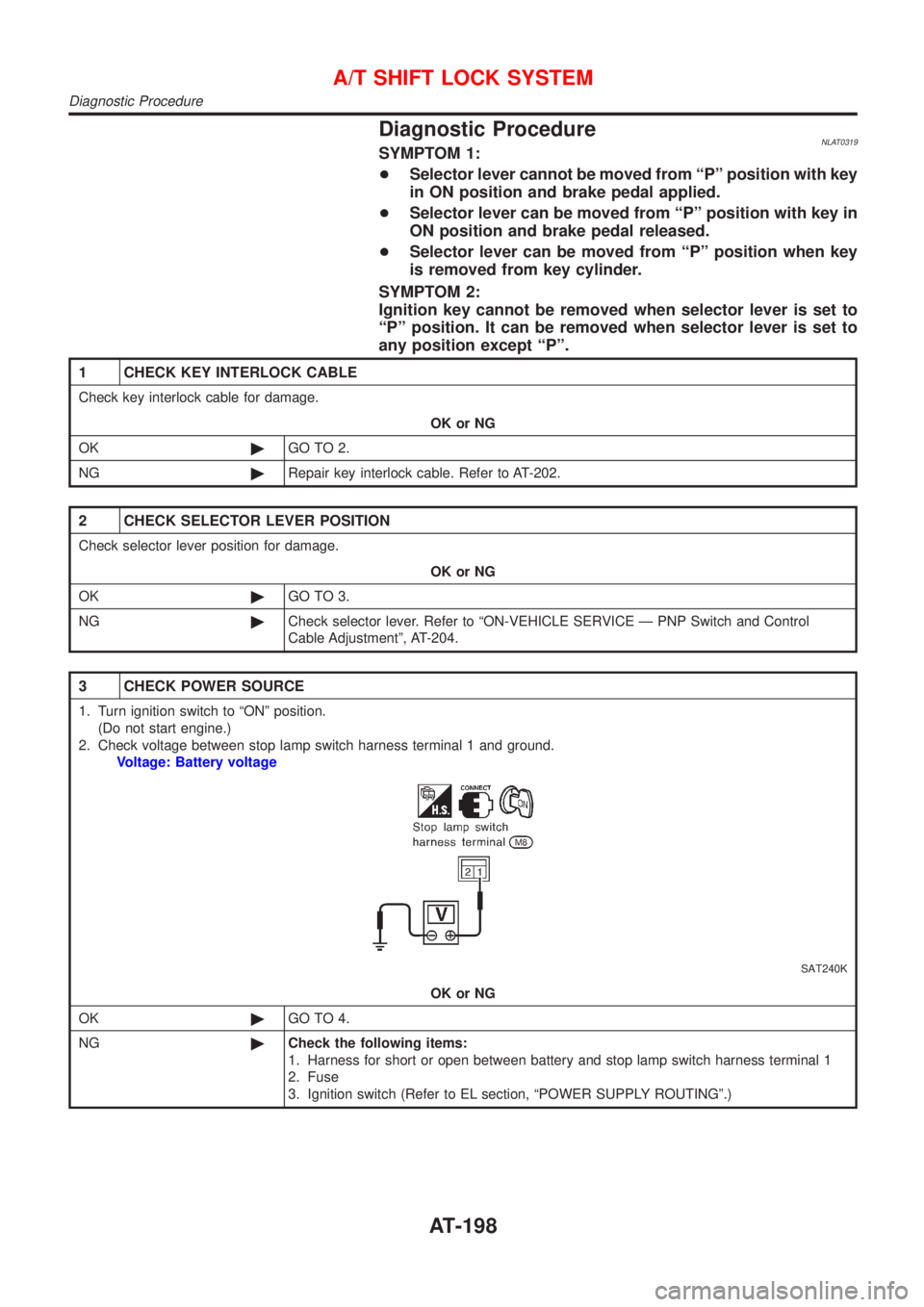
3 CHECK POWER SOURCE
1. Turn ignition switch to ªONº position.
(Do not start engine.)
2. Check voltage between stop lamp switch harness terminal 1 and ground.
Voltage: Battery voltage
SAT240K
OK or NG
OK©GO TO 4.
NG©Check the following items:
1. Harness for short or open between battery and stop lamp switch harness terminal 1
2. Fuse
3. Ignition switch (Refer to EL section, ªPOWER SUPPLY ROUTINGº.)
A/T SHIFT LOCK SYSTEM
Diagnostic Procedure
AT-198
Page 203 of 3051
ComponentsNLAT0320
SAT245K
CAUTION:
+Install key interlock cable in such a way that it will not be
damaged by sharp bends, twists or interference with adja-
cent parts.
+After installing key interlock cable to control device, make
sure that casing cap and bracket are firmly secured in
their positions.
SAT246K
RemovalNLAT03211. Unlock slider by squeezing lock tabs on slider from adjuster
holder and remove interlock rod from cable.
KEY INTERLOCK CABLE
Components
AT-202
Page 204 of 3051
SAT247K
2. Remove lock plate from steering lock assembly and remove
key interlock cable.
SAT247K
InstallationNLAT03221. Turn ignition key to lock position.
2. Set A/T selector lever to P position.
3. Set key interlock cable to steering lock assembly and install
lock plate.
4. Clamp cable to steering column and fix to control cable with
band.
SAT248K
5. Insert interlock rod into adjuster holder.
SAT249K
6. Install casing cap to bracket.
7. Move slider in order to fix adjuster holder to interlock rod.
KEY INTERLOCK CABLE
Removal (Cont'd)
AT-203
Page 265 of 3051
ComponentNLBR0038
NBR366
1. Cable guide
2. Cylinder
3. Toggle lever
4. Pin
5. Pin boot
6. Torque member
7. Inner shim
8. Inner pad
9. Outer pad
10. Outer shim11. Strut
12. O-ring
13. Push rod
14. Key plate
15. Retaining washer
16. Spring
17. Spring cover
18. Snap ring B
19. Piston seal
20. Snap ring A21. Washer
22. Wave washer
23. Washer
24. Bearing
25. Adjuster
26. Cup
27. Piston
28. Piston boot
29. Sleeve
Pad ReplacementNLBR0037WARNING:
Clean brake pads with a vacuum dust collector to minimize the
hazard of airborne particles or other materials.
CAUTION:
+When cylinder body is open, do not depress brake pedal
because piston will pop out.
+Be careful not to damage piston boot or get oil on rotor.
Always replace shims in replacing pads.
+If shims are rusted or show peeling of rubber coat, replace
them with new shims.
REAR DISC BRAKE (CAM & STRUT TYPE)
Component
BR-28
Page 268 of 3051

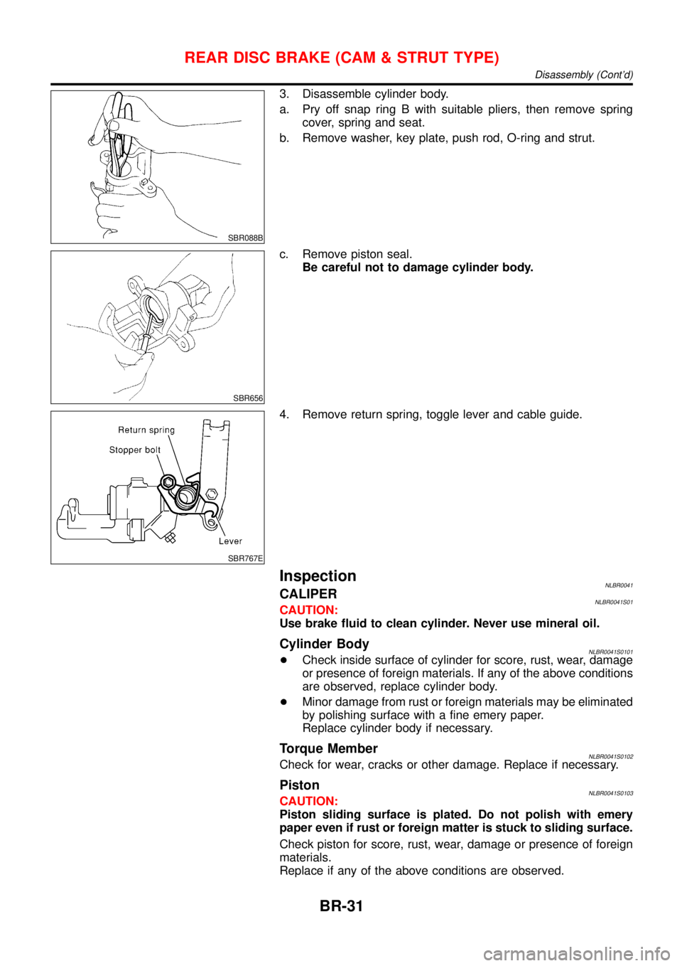
SBR088B
3. Disassemble cylinder body.
a. Pry off snap ring B with suitable pliers, then remove spring
cover, spring and seat.
b. Remove washer, key plate, push rod, O-ring and strut.
SBR656
c. Remove piston seal.
Be careful not to damage cylinder body.
SBR767E
4. Remove return spring, toggle lever and cable guide.
InspectionNLBR0041CALIPERNLBR0041S01CAUTION:
Use brake fluid to clean cylinder. Never use mineral oil.
Cylinder BodyNLBR0041S0101+Check inside surface of cylinder for score, rust, wear, damage
or presence of foreign materials. If any of the above conditions
are observed, replace cylinder body.
+Minor damage from rust or foreign materials may be eliminated
by polishing surface with a fine emery paper.
Replace cylinder body if necessary.
Torque MemberNLBR0041S0102Check for wear, cracks or other damage. Replace if necessary.
PistonNLBR0041S0103CAUTION:
Piston sliding surface is plated. Do not polish with emery
paper even if rust or foreign matter is stuck to sliding surface.
Check piston for score, rust, wear, damage or presence of foreign
materials.
Replace if any of the above conditions are observed.
REAR DISC BRAKE (CAM & STRUT TYPE)
Disassembly (Cont’d)
BR-31
Page 270 of 3051
SBR248B
2. Generously apply rubber grease to strut and push rod to make
insertion easy.
SBR893
3. Fit push rod into square hole in key plate. Also match convex
portion of key plate with concave portion of cylinder.
SBR754E
4. Install rod, push rod and key plate.
SBR869CB
SBR879-B
5. Install seat, spring, spring cover and snap ring B with suitable
press and drift.
REAR DISC BRAKE (CAM & STRUT TYPE)
Assembly (Cont’d)
BR-33
Page 299 of 3051
PBR455D
ACTIVE TEST PROCEDURENLBR0093S04+When conducting Active test, vehicle must be stationary.
+When ABS warning lamp stays on, never conduct Active test.
1. Turn ignition switch OFF.
2. Connect CONSULT-II to data link connector.
3. Start engine.
4. Touch“START”on CONSULT-II screen.
C2SSE01
5. Touch“ABS”.
C2SDM01
6. Touch“ACTIVE TEST”.
PBR976C
7. Select active test item by touching screen.
PBR934C
8. Touch“START”.
9. Carry out the active test by touching screen key.
ON BOARD DIAGNOSTIC SYSTEM DESCRIPTIONABS
CONSULT-II Inspection Procedure (Cont’d)
BR-62
Page 350 of 3051
NBT100
2. Remove inside handle escutcheon A.
3. Remove screw securing inside handle.
4. Detach bell crank at lock knob joining area.
5. Detach inside handle rod on the door lock assembly side.
6. Slide inside handle backward and remove inside handle.
7. Remove rod from inside handle.
NBT101
8. Detach key lock rod and outside handle rod at joining area (on
the outside handle side).
9. Disconnect door lock actuator connector.
10. Remove screws securing door lock assembly, then remove
door lock assembly.
11. Remove bolts securing outside handle, then remove outside
handle assembly.
DOOR
Front Door Lock (Cont'd)
BT-19