Page 1903 of 3051
DIAGNOSTIC PROCEDURE 2 (KEY SWITCH INSERT
SIGNAL CHECK)
=NLEL0455S04
1 CHECK KEY SWITCH INPUT SIGNAL
Check voltage between time control unit terminal 22 and ground.
NEL653
OK or NG
OK©Key switch is OK.
NG©GO TO 2.
2 CHECK KEY SWITCH (INSERT)
Check continuity between terminals 1 and 2.
NEL787
OK or NG
OK©Check the following.
+10A fuse [No. 12, located in fuse block (J/B)]
+Harness for open or short between key switch and fuse
+Harness for open or short between time control unit and key switch
NG©Replace key switch.
WARNING CHIME
Trouble Diagnoses (Cont'd)
EL-172
Page 1940 of 3051

carried out. Subsequently, when the repaired audio unit is delivered to the final user again, it will be in the
ªNEWº state as to enable re-linking the audio unit to the vehicle's immobiliser system. As a result of the above,
repair of the audio unit can only be done by an authorized Clarion representative.
Service instruction
Item Radio linked with IMMU and/or SECU
Battery disconnection No additional action required
Radio needs repair Repair needs to be done by authorised representative of radio manufacturer since radio
cannot be operated unless it is reset to NEW state, using special decoding equipment
Replacement of radio by new part Radio is delivered in NEW state. If possible, the radio will automatically link up with the
immobiliser system. If this appears not possible, CATS code needs to be manually input
Transferring radio to another vehicle /
replacement of radio by an ªoldº partRadio needs to be reset to NEW state by authorised representative of radio manufacturer
Replacement of IMMU by new part Radio will request for CATS code input prior to establishing the link with the IMMU
Replacement of IMMU by old part If a radio code has already been stored in memory of the IMMU, the radio cannot be
linked to it. After switching on the radio, it will display ªSECUREº after 1 minute. Operation
can only be established after resetting the ratio by an authorised representative of radio
manufacturer
No communication from IMMU to
radioRadio will display ªSECUREº after 180 attempts to communicate with IMMU. Further use
of radio impossible until communication is established again, or after radio is reset by
authorised representative of (radio) manufacturer
CATS code input procedure
1. Radio displays ªCODE INº after the power is switched ON.
2. Enter CATS code (4±digits) by pressing the preset buttons (using 1 to 4).
Press the preset buttons for the necessary amount of times for the number of each digits.
e.g. CATS code is ª5432º
Press No. 1 preset button for 5 times
Press No. 2 preset button for 4 times
Press No. 3 preset button for 3 times
Press No. 4 preset button for 2 times
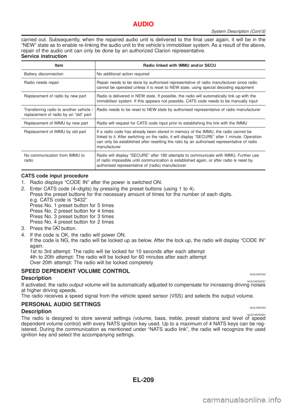
3. Press the
button.
4. If the code is OK, the radio will power ON.
If the code is NG, the radio will be locked up as below. After the lock up, the radio will display ªCODE INº
again.
1st to 3rd attempt: The radio will be locked for 10 seconds after each attempt
4th to 20th attempt: The radio will be locked for 60 minutes after each attempt
Over 20th attempt: The radio will be locked completely
SPEED DEPENDENT VOLUME CONTROLNLEL0497S02DescriptionNLEL0497S0201If activated, the radio output volume will be automatically adjusted to compensate for increasing driving noises
at higher driving speeds.
The radio receives a speed signal from the vehicle speed sensor (VSS) and selects the output volume.
PERSONAL AUDIO SETTINGSNLEL0497S03DescriptionNLEL0497S0301The radio is designed to store several settings (volume, bass, treble, preset stations and level of speed
dependent volume control) with every NATS ignition key used. Up to a maximum of 4 NATS keys can be reg-
istered. During the communication as mentioned under ªNATS audio linkº, the radio will recognize the used
ignition key and select the accompanying settings.
AUDIO
System Description (Cont'd)
EL-209
Page 1988 of 3051

Component Parts and Harness Connector
Location/LHD Models
NLEL0526For details, refer to ªELECTRICAL UNIT LOCATIONº (EL-442) and ªHARNESS LAYOUTº (EL-452).
System Description/LHD ModelsNLEL0502OPERATIONNLEL0502S02Power door lock/unlock operation by door key cylinder
+With the key inserted into front door key cylinder, turning it to LOCK will lock all doors.
+With the key inserted into front door key cylinder, turning it to UNLOCK will unlock all doors.
Power door lock/unlock operation by multi-remote controller (If equipped)
+Pressing multi-remote controller LOCK button will lock all doors.
+Pressing multi-remote controller UNLOCK button once will unlock driver door. Then, if an unlock signal is
sent from the remote controller again within 5 seconds, all other doors will be unlocked.
Power door lock/unlock operation by lock/unlock switch
+With lock/unlock switch on driver door trim setting to LOCK will lock all doors.
+With lock/unlock switch on driver door trim setting to UNLOCK will unlock all doors.
Key reminder system
+If the ignition key is in the ignition key cylinder and driver door is open, setting lock/unlock switch, lock
knob, key or multi-remote controller to ªLOCKº locks the door once but then immediately unlocks all doors.
(signal from door unlock sensor driver side)
POWER DOOR LOCK
Component Parts and Harness Connector Location/LHD Models
EL-257
Page 2003 of 3051
Trouble Diagnoses/LHD ModelsNLEL0505SYMPTOM CHARTNLEL0505S02
REFERENCE PAGE (EL- ) 273 274 275 276 277 278 279
SYMPTOM
Main power supply and ground circuit check
Door lock/unlock switch check
Door key cylinder switch check
Door lock actuator check
Door switch check
Door unlock sensor check
Key switch check
1Power door lock does not operate using any
switch.XX
2Power door lock does not operate with lock/
unlock switch.X
3Power door lock does not operate with door key
cylinder switch.X
4 Specific door lock actuator does not operate. X
5 *Key reminder system does not operate. X X X
X: Applicable
*: Make sure the power door lock system operates properly.
POWER DOOR LOCK
Trouble Diagnoses/LHD Models
EL-272
Page 2006 of 3051
DOOR KEY CYLINDER SWITCH CHECKNLEL0505S05
1 CHECK DOOR KEY CYLINDER SWITCH INPUT SIGNAL (LOCK/UNLOCK SIGNAL)
Check voltage between time control unit harness connector terminals 28 or 29 and ground.
NEL676
Refer to wiring diagram.
OK or NG
OK©Door key cylinder switch is OK.
NG©GO TO 2.
2 CHECK DOOR KEY CYLINDER SWITCH
1. Disconnect door key cylinder switch harness connector.
2. Check continuity between door key cylinder switch terminals.
NEL677
OK or NG
OK©Check the following.
+Door key cylinder switch ground circuit
+Harness for open or short between time control unit and door key cylinder switch
NG©Replace door key cylinder switch.
POWER DOOR LOCK
Trouble Diagnoses/LHD Models (Cont'd)
EL-275
Page 2010 of 3051
2 CHECK DOOR UNLOCK SENSOR
1. Disconnect door unlock sensor connector.
2. Check continuity between door unlock sensor terminals 2 and 4.
NEL683
OK or NG
OK©Check the following.
+Door unlock sensor ground circuit
+Harness for open or short between time control unit and door unlock sensor
NG©Replace door unlock sensor.
KEY SWITCH (INSERT) CHECKNLEL0505S11
1 CHECK KEY SWITCH INPUT SIGNAL
Check voltage between time control unit terminal 22 and ground.
NEL653
Refer to wiring diagram.
OK or NG
OK©Key switch is OK.
NG©GO TO 2.
POWER DOOR LOCK
Trouble Diagnoses/LHD Models (Cont'd)
EL-279
Page 2011 of 3051
2 CHECK KEY SWITCH (INSERT)
Check continuity between key switch terminals 1 and 2.
NEL787
OK or NG
OK©Check the following.
+10A fuse [No. 12, located in fuse block (J/B)]
+Harness for open or short between key switch and fuse
+Harness for open or short between time control unit and key switch
NG©Replace key switch.
POWER DOOR LOCK
Trouble Diagnoses/LHD Models (Cont'd)
EL-280
Page 2012 of 3051

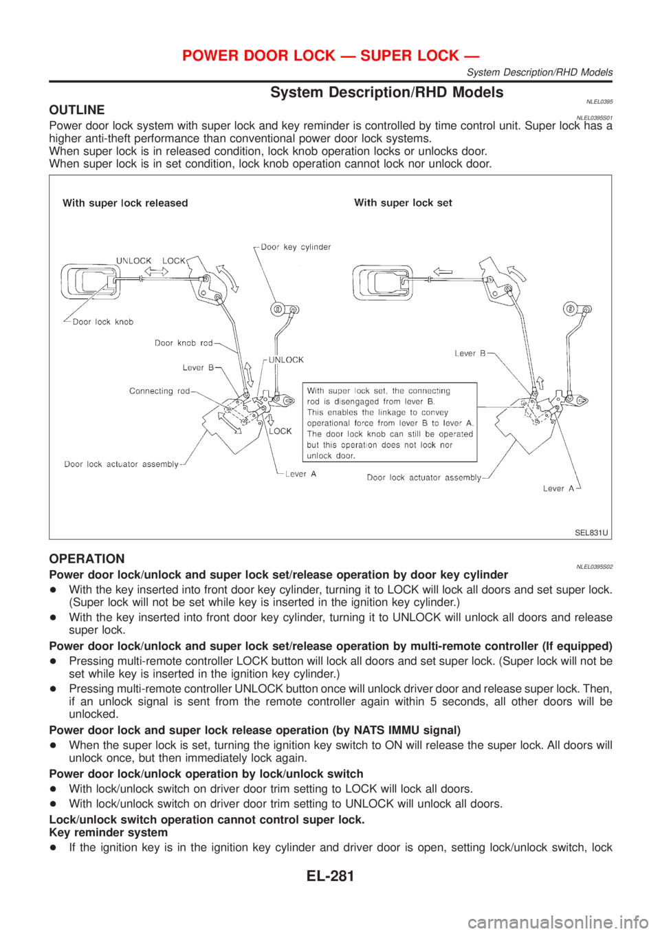
System Description/RHD ModelsNLEL0395OUTLINENLEL0395S01Power door lock system with super lock and key reminder is controlled by time control unit. Super lock has a
higher anti-theft performance than conventional power door lock systems.
When super lock is in released condition, lock knob operation locks or unlocks door.
When super lock is in set condition, lock knob operation cannot lock nor unlock door.
SEL831U
OPERATIONNLEL0395S02Power door lock/unlock and super lock set/release operation by door key cylinder
+With the key inserted into front door key cylinder, turning it to LOCK will lock all doors and set super lock.
(Super lock will not be set while key is inserted in the ignition key cylinder.)
+With the key inserted into front door key cylinder, turning it to UNLOCK will unlock all doors and release
super lock.
Power door lock/unlock and super lock set/release operation by multi-remote controller (If equipped)
+Pressing multi-remote controller LOCK button will lock all doors and set super lock. (Super lock will not be
set while key is inserted in the ignition key cylinder.)
+Pressing multi-remote controller UNLOCK button once will unlock driver door and release super lock. Then,
if an unlock signal is sent from the remote controller again within 5 seconds, all other doors will be
unlocked.
Power door lock and super lock release operation (by NATS IMMU signal)
+When the super lock is set, turning the ignition key switch to ON will release the super lock. All doors will
unlock once, but then immediately lock again.
Power door lock/unlock operation by lock/unlock switch
+With lock/unlock switch on driver door trim setting to LOCK will lock all doors.
+With lock/unlock switch on driver door trim setting to UNLOCK will unlock all doors.
Lock/unlock switch operation cannot control super lock.
Key reminder system
+If the ignition key is in the ignition key cylinder and driver door is open, setting lock/unlock switch, lock
POWER DOOR LOCK Ð SUPER LOCK Ð
System Description/RHD Models
EL-281