Page 889 of 3051
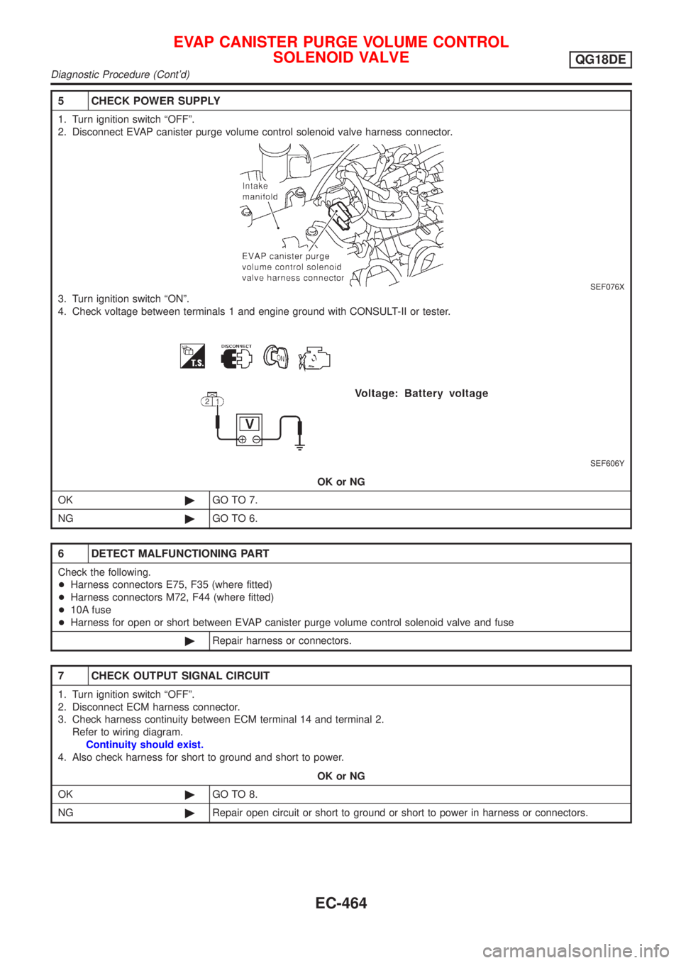
5 CHECK POWER SUPPLY
1. Turn ignition switch ªOFFº.
2. Disconnect EVAP canister purge volume control solenoid valve harness connector.
SEF076X
3. Turn ignition switch ªONº.
4. Check voltage between terminals 1 and engine ground with CONSULT-II or tester.
SEF606Y
OK or NG
OK©GO TO 7.
NG©GO TO 6.
6 DETECT MALFUNCTIONING PART
Check the following.
+Harness connectors E75, F35 (where fitted)
+Harness connectors M72, F44 (where fitted)
+10A fuse
+Harness for open or short between EVAP canister purge volume control solenoid valve and fuse
©Repair harness or connectors.
7 CHECK OUTPUT SIGNAL CIRCUIT
1. Turn ignition switch ªOFFº.
2. Disconnect ECM harness connector.
3. Check harness continuity between ECM terminal 14 and terminal 2.
Refer to wiring diagram.
Continuity should exist.
4. Also check harness for short to ground and short to power.
OK or NG
OK©GO TO 8.
NG©Repair open circuit or short to ground or short to power in harness or connectors.
EVAP CANISTER PURGE VOLUME CONTROL
SOLENOID VALVE
QG18DE
Diagnostic Procedure (Cont'd)
EC-464
Page 896 of 3051
3 DETECT MALFUNCTIONING PART
Check the following.
+15A fuse
+Harness connectors E76, F36
+Harness for open or short between fuse and ECM relay
+ECM relay
+Harness for open or short between IACV-AAC and ECM relay
©Repair harness or connectors or replace fuse or ECM relay.
4 CHECK OUTPUT SIGNAL CIRCUIT
1. Turn ignition switch ªOFFº.
2. Disconnect ECM harness connector.
3. Check harness continuity between
ECM terminal 6 and IACV-AAC valve terminal 1,
ECM terminal 7 and IACV-AAC valve terminal 4,
ECM terminal 15 and IACV-AAC valve terminal 3,
ECM terminal 16 and IACV-AAC valve terminal 6.
Refer to wiring diagram.
Continuity should exist.
4. Also check harness for short to ground and short to power.
OK or NG
OK©GO TO 5.
NG©Repair open circuit or short to ground or short to power in harness or connectors.
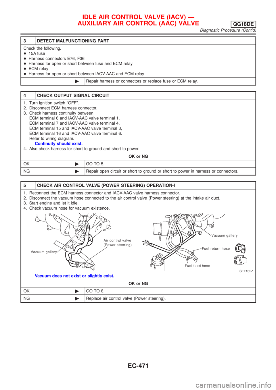
5 CHECK AIR CONTROL VALVE (POWER STEERING) OPERATION-I
1. Reconnect the ECM harness connector and IACV-AAC valve harness connector.
2. Disconnect the vacuum hose connected to the air control valve (Power steering) at the intake air duct.
3. Start engine and let it idle.
4. Check vacuum hose for vacuum existence.
SEF162Z
Vacuum does not exist or slightly exist.
OK or NG
OK©GO TO 6.
NG©Replace air control valve (Power steering).
IDLE AIR CONTROL VALVE (IACV) Ð
AUXILIARY AIR CONTROL (AAC) VALVE
QG18DE
Diagnostic Procedure (Cont'd)
EC-471
Page 904 of 3051
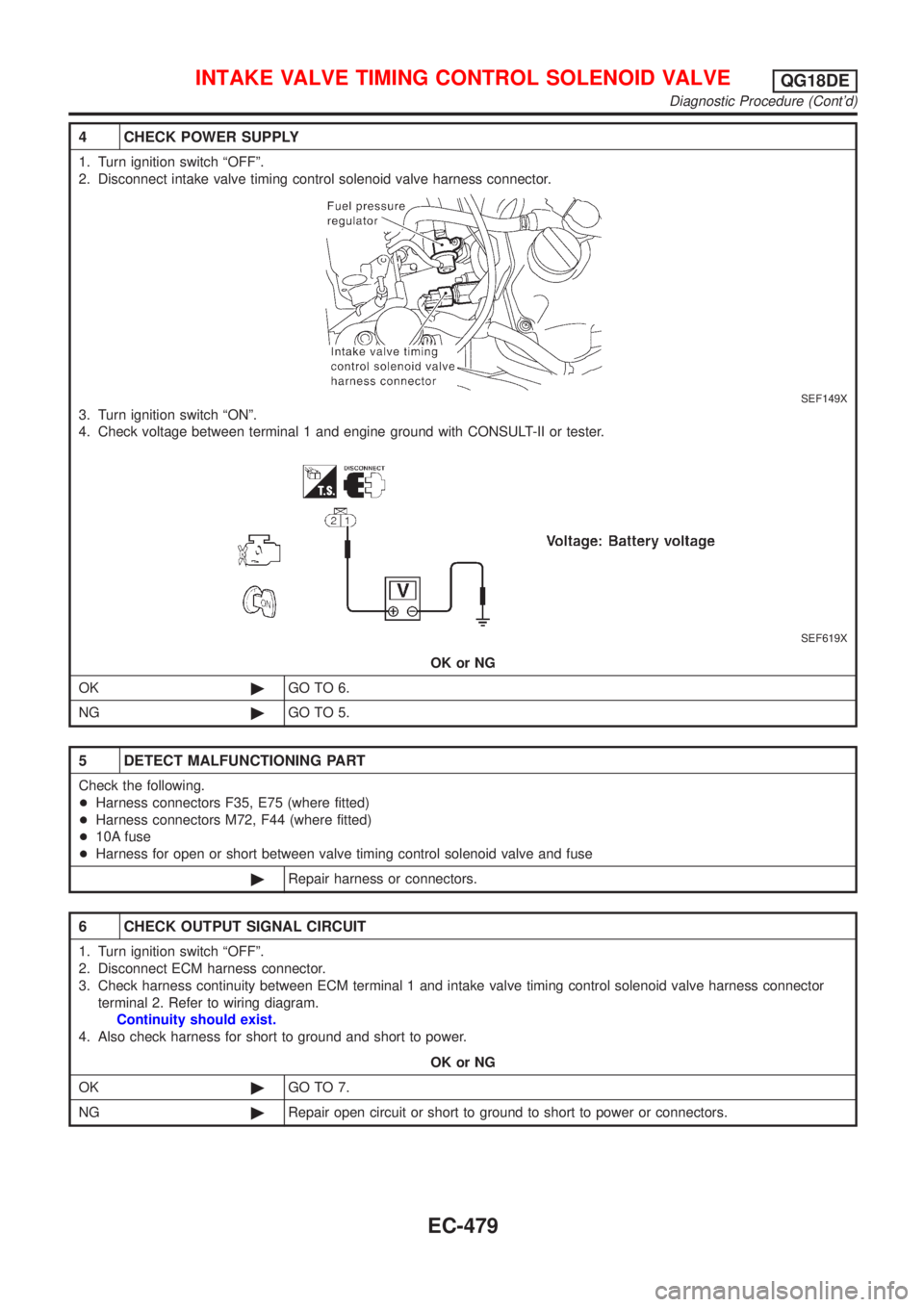
4 CHECK POWER SUPPLY
1. Turn ignition switch ªOFFº.
2. Disconnect intake valve timing control solenoid valve harness connector.
SEF149X
3. Turn ignition switch ªONº.
4. Check voltage between terminal 1 and engine ground with CONSULT-II or tester.
SEF619X
OK or NG
OK©GO TO 6.
NG©GO TO 5.
5 DETECT MALFUNCTIONING PART
Check the following.
+Harness connectors F35, E75 (where fitted)
+Harness connectors M72, F44 (where fitted)
+10A fuse
+Harness for open or short between valve timing control solenoid valve and fuse
©Repair harness or connectors.
6 CHECK OUTPUT SIGNAL CIRCUIT
1. Turn ignition switch ªOFFº.
2. Disconnect ECM harness connector.
3. Check harness continuity between ECM terminal 1 and intake valve timing control solenoid valve harness connector
terminal 2. Refer to wiring diagram.
Continuity should exist.
4. Also check harness for short to ground and short to power.
OK or NG
OK©GO TO 7.
NG©Repair open circuit or short to ground to short to power or connectors.
INTAKE VALVE TIMING CONTROL SOLENOID VALVEQG18DE
Diagnostic Procedure (Cont'd)
EC-479
Page 912 of 3051
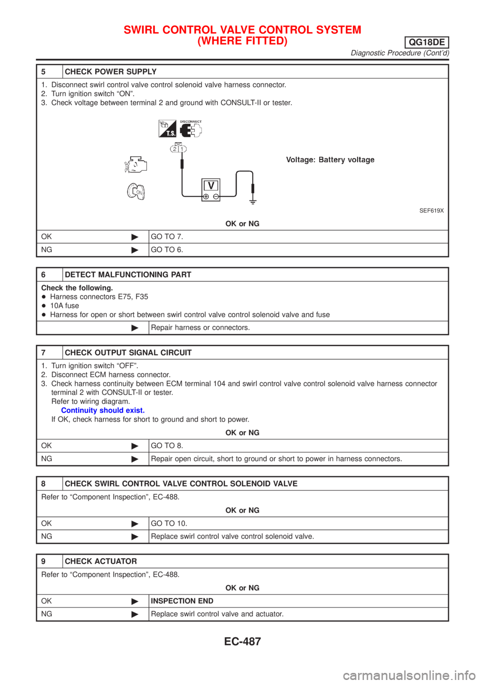
5 CHECK POWER SUPPLY
1. Disconnect swirl control valve control solenoid valve harness connector.
2. Turn ignition switch ªONº.
3. Check voltage between terminal 2 and ground with CONSULT-II or tester.
SEF619X
OK or NG
OK©GO TO 7.
NG©GO TO 6.
6 DETECT MALFUNCTIONING PART
Check the following.
+Harness connectors E75, F35
+10A fuse
+Harness for open or short between swirl control valve control solenoid valve and fuse
©Repair harness or connectors.
7 CHECK OUTPUT SIGNAL CIRCUIT
1. Turn ignition switch ªOFFº.
2. Disconnect ECM harness connector.
3. Check harness continuity between ECM terminal 104 and swirl control valve control solenoid valve harness connector
terminal 2 with CONSULT-II or tester.
Refer to wiring diagram.
Continuity should exist.
If OK, check harness for short to ground and short to power.
OK or NG
OK©GO TO 8.
NG©Repair open circuit, short to ground or short to power in harness connectors.
8 CHECK SWIRL CONTROL VALVE CONTROL SOLENOID VALVE
Refer to ªComponent Inspectionº, EC-488.
OK or NG
OK©GO TO 10.
NG©Replace swirl control valve control solenoid valve.
9 CHECK ACTUATOR
Refer to ªComponent Inspectionº, EC-488.
OK or NG
OK©INSPECTION END
NG©Replace swirl control valve and actuator.
SWIRL CONTROL VALVE CONTROL SYSTEM
(WHERE FITTED)
QG18DE
Diagnostic Procedure (Cont'd)
EC-487
Page 923 of 3051
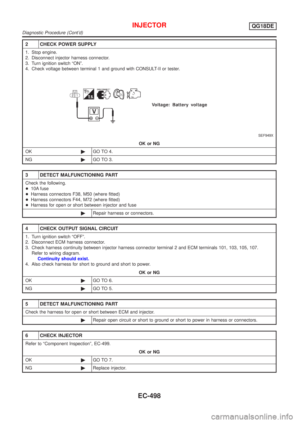
2 CHECK POWER SUPPLY
1. Stop engine.
2. Disconnect injector harness connector.
3. Turn ignition switch ªONº.
4. Check voltage between terminal 1 and ground with CONSULT-II or tester.
SEF949X
OK or NG
OK©GO TO 4.
NG©GO TO 3.
3 DETECT MALFUNCTIONING PART
Check the following.
+10A fuse
+Harness connectors F38, M50 (where fitted)
+Harness connectors F44, M72 (where fitted)
+Harness for open or short between injector and fuse
©Repair harness or connectors.
4 CHECK OUTPUT SIGNAL CIRCUIT
1. Turn ignition switch ªOFFº.
2. Disconnect ECM harness connector.
3. Check harness continuity between injector harness connector terminal 2 and ECM terminals 101, 103, 105, 107.
Refer to wiring diagram.
Continuity should exist.
4. Also check harness for short to ground and short to power.
OK or NG
OK©GO TO 6.
NG©GO TO 5.
5 DETECT MALFUNCTIONING PART
Check the harness for open or short between ECM and injector.
©Repair open circuit or short to ground or short to power in harness or connectors.
6 CHECK INJECTOR
Refer to ªComponent Inspectionº, EC-499.
OK or NG
OK©GO TO 7.
NG©Replace injector.
INJECTORQG18DE
Diagnostic Procedure (Cont'd)
EC-498
Page 932 of 3051
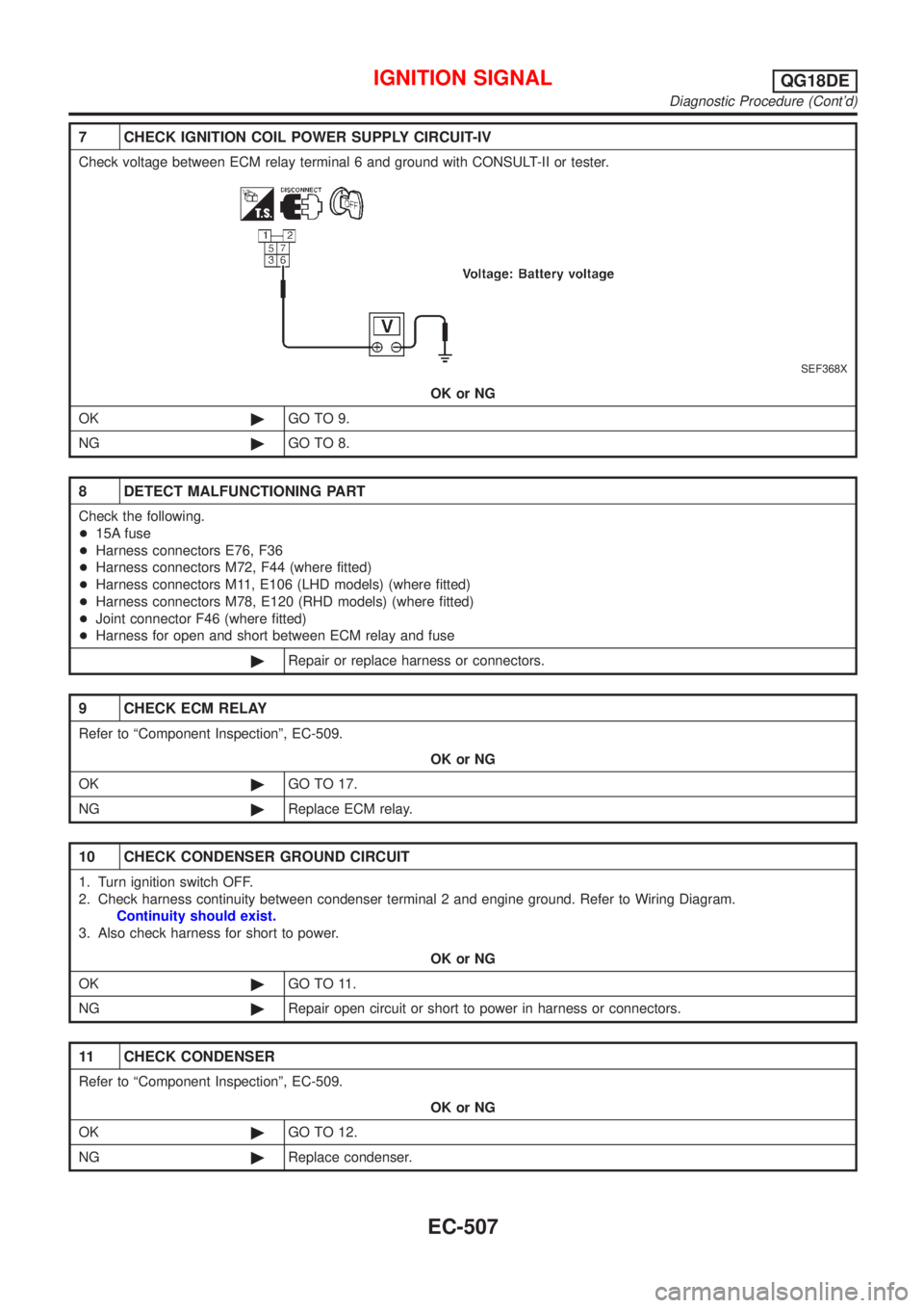
7 CHECK IGNITION COIL POWER SUPPLY CIRCUIT-IV
Check voltage between ECM relay terminal 6 and ground with CONSULT-II or tester.
SEF368X
OK or NG
OK©GO TO 9.
NG©GO TO 8.
8 DETECT MALFUNCTIONING PART
Check the following.
+15A fuse
+Harness connectors E76, F36
+Harness connectors M72, F44 (where fitted)
+Harness connectors M11, E106 (LHD models) (where fitted)
+Harness connectors M78, E120 (RHD models) (where fitted)
+Joint connector F46 (where fitted)
+Harness for open and short between ECM relay and fuse
©Repair or replace harness or connectors.
9 CHECK ECM RELAY
Refer to ªComponent Inspectionº, EC-509.
OK or NG
OK©GO TO 17.
NG©Replace ECM relay.
10 CHECK CONDENSER GROUND CIRCUIT
1. Turn ignition switch OFF.
2. Check harness continuity between condenser terminal 2 and engine ground. Refer to Wiring Diagram.
Continuity should exist.
3. Also check harness for short to power.
OK or NG
OK©GO TO 11.
NG©Repair open circuit or short to power in harness or connectors.
11 CHECK CONDENSER
Refer to ªComponent Inspectionº, EC-509.
OK or NG
OK©GO TO 12.
NG©Replace condenser.
IGNITION SIGNALQG18DE
Diagnostic Procedure (Cont'd)
EC-507
Page 946 of 3051
3 DETECT MALFUNCTIONING PART
Check the following.
+10A fuse
+15A fuse
+Harness for open or short between fuse and fuel pump relay
©Repair harness or connectors.
4 CHECK POWER GROUND CIRCUIT
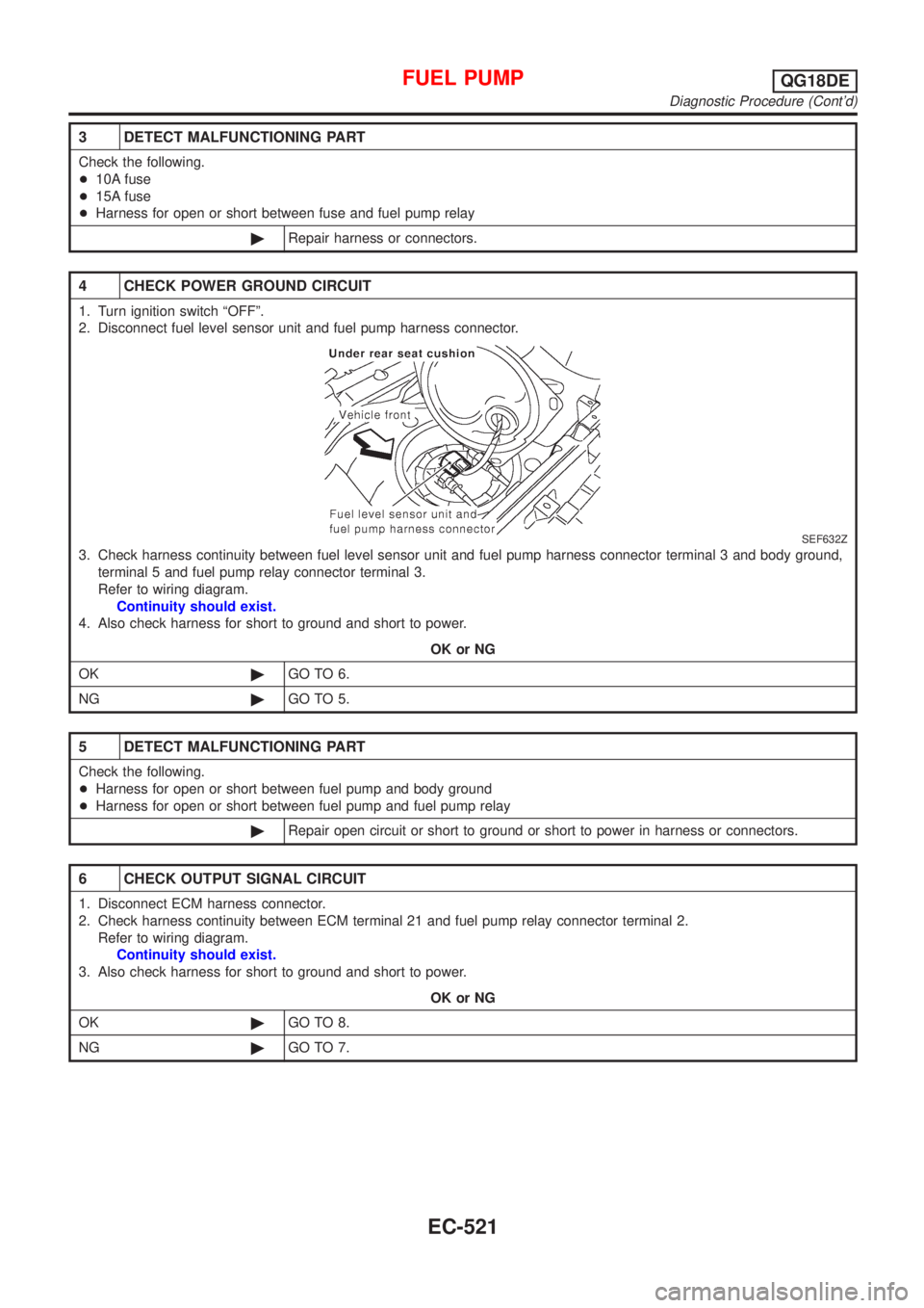
1. Turn ignition switch ªOFFº.
2. Disconnect fuel level sensor unit and fuel pump harness connector.
SEF632Z
3. Check harness continuity between fuel level sensor unit and fuel pump harness connector terminal 3 and body ground,
terminal 5 and fuel pump relay connector terminal 3.
Refer to wiring diagram.
Continuity should exist.
4. Also check harness for short to ground and short to power.
OK or NG
OK©GO TO 6.
NG©GO TO 5.
5 DETECT MALFUNCTIONING PART
Check the following.
+Harness for open or short between fuel pump and body ground
+Harness for open or short between fuel pump and fuel pump relay
©Repair open circuit or short to ground or short to power in harness or connectors.
6 CHECK OUTPUT SIGNAL CIRCUIT
1. Disconnect ECM harness connector.
2. Check harness continuity between ECM terminal 21 and fuel pump relay connector terminal 2.
Refer to wiring diagram.
Continuity should exist.
3. Also check harness for short to ground and short to power.
OK or NG
OK©GO TO 8.
NG©GO TO 7.
FUEL PUMPQG18DE
Diagnostic Procedure (Cont'd)
EC-521
Page 1099 of 3051
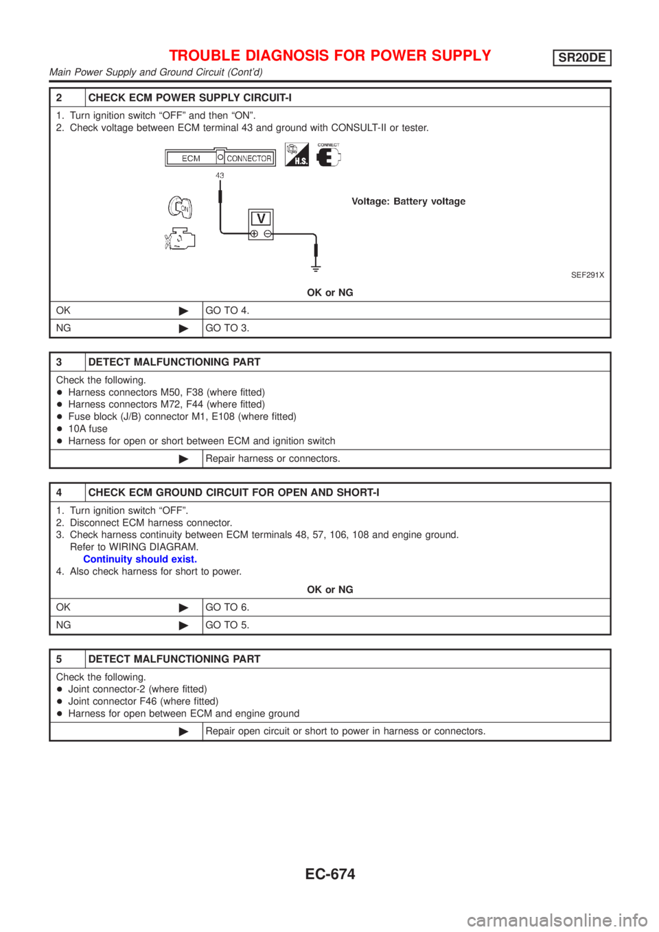
2 CHECK ECM POWER SUPPLY CIRCUIT-I
1. Turn ignition switch ªOFFº and then ªONº.
2. Check voltage between ECM terminal 43 and ground with CONSULT-II or tester.
SEF291X
OK or NG
OK©GO TO 4.
NG©GO TO 3.
3 DETECT MALFUNCTIONING PART
Check the following.
+Harness connectors M50, F38 (where fitted)
+Harness connectors M72, F44 (where fitted)
+Fuse block (J/B) connector M1, E108 (where fitted)
+10A fuse
+Harness for open or short between ECM and ignition switch
©Repair harness or connectors.
4 CHECK ECM GROUND CIRCUIT FOR OPEN AND SHORT-I
1. Turn ignition switch ªOFFº.
2. Disconnect ECM harness connector.
3. Check harness continuity between ECM terminals 48, 57, 106, 108 and engine ground.
Refer to WIRING DIAGRAM.
Continuity should exist.
4. Also check harness for short to power.
OK or NG
OK©GO TO 6.
NG©GO TO 5.
5 DETECT MALFUNCTIONING PART
Check the following.
+Joint connector-2 (where fitted)
+Joint connector F46 (where fitted)
+Harness for open between ECM and engine ground
©Repair open circuit or short to power in harness or connectors.
TROUBLE DIAGNOSIS FOR POWER SUPPLYSR20DE
Main Power Supply and Ground Circuit (Cont'd)
EC-674