Page 1425 of 3051
3 DETECT MALFUNCTIONING PART
Check the following.
+15A fuse
+Harness connectors E76, F36
+Harness for open or short between fuse and ECM relay
+ECM relay
+Harness for open or short between IACV-AAC and ECM relay
©Repair harness or connectors or replace fuse or ECM relay.
4 CHECK OUTPUT SIGNAL CIRCUIT
1. Turn ignition switch ªOFFº.
2. Disconnect ECM harness connector.
3. Check harness continuity between
ECM terminal 6 and IACV-AAC valve terminal 1,
ECM terminal 7 and IACV-AAC valve terminal 4,
ECM terminal 15 and IACV-AAC valve terminal 3,
ECM terminal 16 and IACV-AAC valve terminal 6.
Refer to wiring diagram.
Continuity should exist.
4. Also check harness for short to ground and short to power.
OK or NG
OK©GO TO 5.
NG©Repair open circuit or short to ground or short to power in harness or connectors.
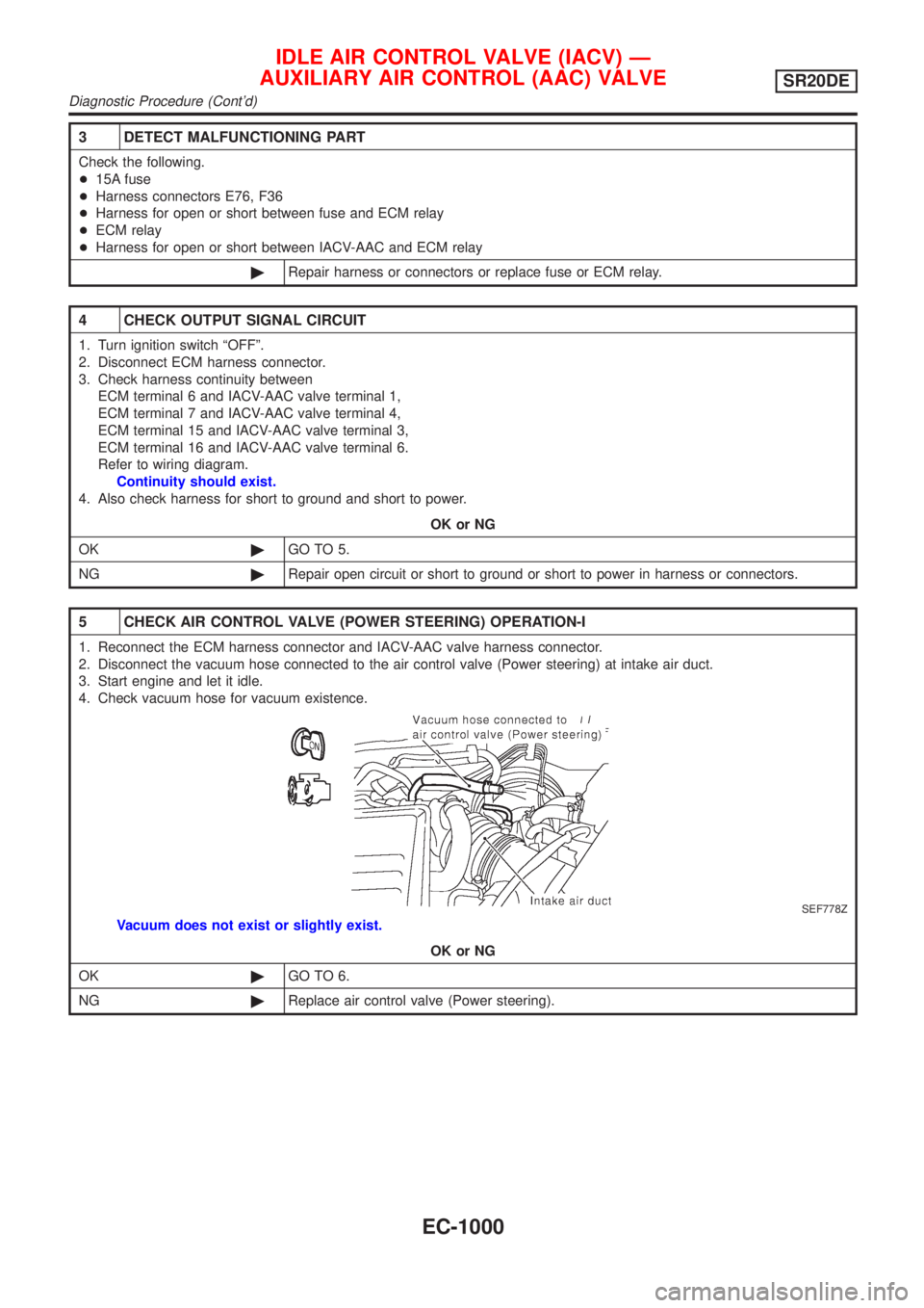
5 CHECK AIR CONTROL VALVE (POWER STEERING) OPERATION-I
1. Reconnect the ECM harness connector and IACV-AAC valve harness connector.
2. Disconnect the vacuum hose connected to the air control valve (Power steering) at intake air duct.
3. Start engine and let it idle.
4. Check vacuum hose for vacuum existence.
SEF778Z
Vacuum does not exist or slightly exist.
OK or NG
OK©GO TO 6.
NG©Replace air control valve (Power steering).
IDLE AIR CONTROL VALVE (IACV) Ð
AUXILIARY AIR CONTROL (AAC) VALVE
SR20DE
Diagnostic Procedure (Cont'd)
EC-1000
Page 1450 of 3051
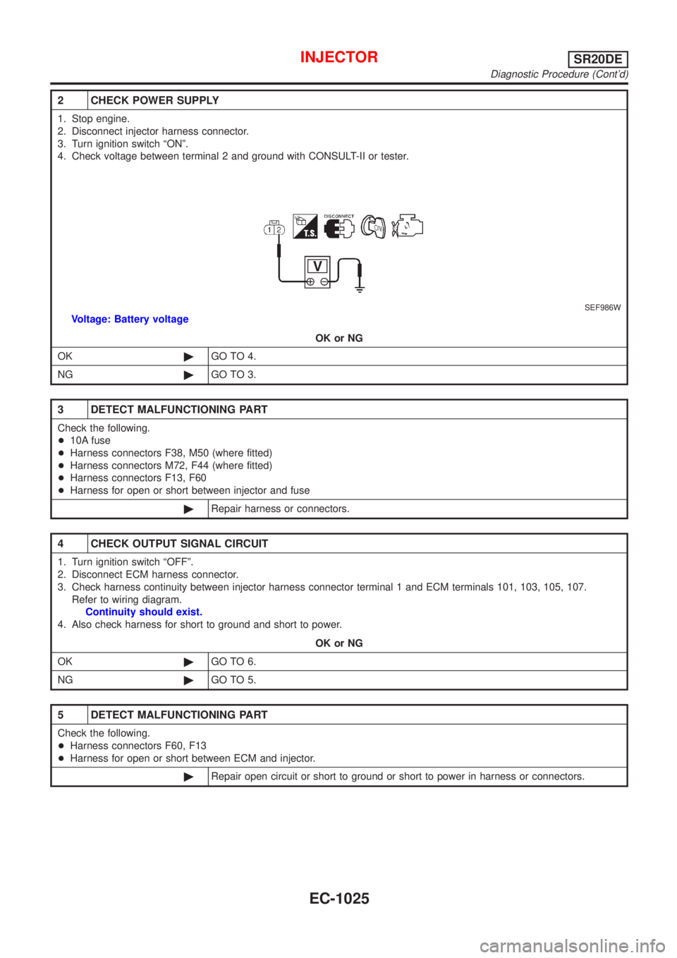
2 CHECK POWER SUPPLY
1. Stop engine.
2. Disconnect injector harness connector.
3. Turn ignition switch ªONº.
4. Check voltage between terminal 2 and ground with CONSULT-II or tester.
SEF986W
Voltage: Battery voltage
OK or NG
OK©GO TO 4.
NG©GO TO 3.
3 DETECT MALFUNCTIONING PART
Check the following.
+10A fuse
+Harness connectors F38, M50 (where fitted)
+Harness connectors M72, F44 (where fitted)
+Harness connectors F13, F60
+Harness for open or short between injector and fuse
©Repair harness or connectors.
4 CHECK OUTPUT SIGNAL CIRCUIT
1. Turn ignition switch ªOFFº.
2. Disconnect ECM harness connector.
3. Check harness continuity between injector harness connector terminal 1 and ECM terminals 101, 103, 105, 107.
Refer to wiring diagram.
Continuity should exist.
4. Also check harness for short to ground and short to power.
OK or NG
OK©GO TO 6.
NG©GO TO 5.
5 DETECT MALFUNCTIONING PART
Check the following.
+Harness connectors F60, F13
+Harness for open or short between ECM and injector.
©Repair open circuit or short to ground or short to power in harness or connectors.
INJECTORSR20DE
Diagnostic Procedure (Cont'd)
EC-1025
Page 1462 of 3051
3 DETECT MALFUNCTIONING PART
Check the following.
+10A fuse
+15A fuse
+Harness for open or short between fuse and fuel pump relay
©Repair harness or connectors.
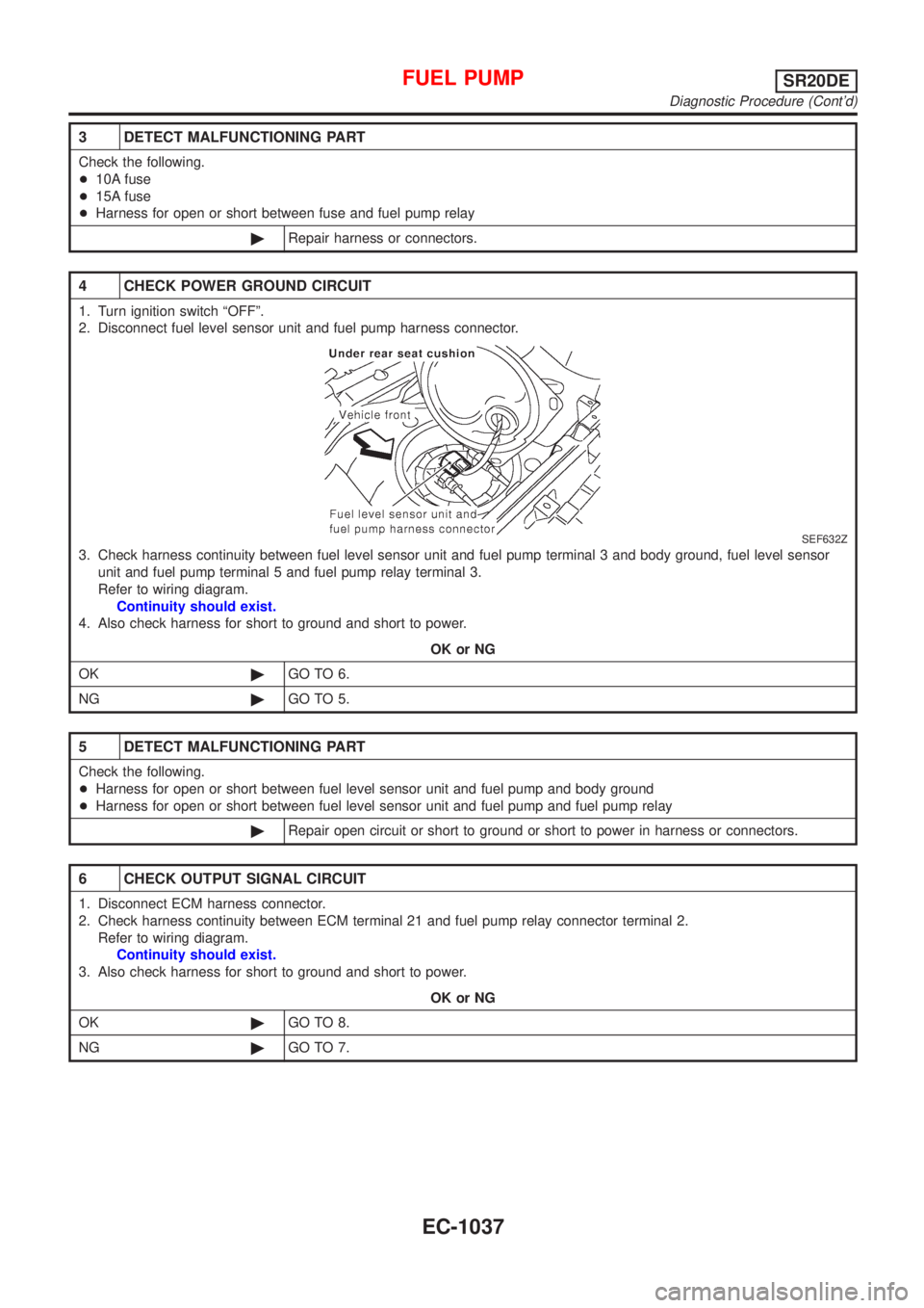
4 CHECK POWER GROUND CIRCUIT
1. Turn ignition switch ªOFFº.
2. Disconnect fuel level sensor unit and fuel pump harness connector.
SEF632Z
3. Check harness continuity between fuel level sensor unit and fuel pump terminal 3 and body ground, fuel level sensor
unit and fuel pump terminal 5 and fuel pump relay terminal 3.
Refer to wiring diagram.
Continuity should exist.
4. Also check harness for short to ground and short to power.
OK or NG
OK©GO TO 6.
NG©GO TO 5.
5 DETECT MALFUNCTIONING PART
Check the following.
+Harness for open or short between fuel level sensor unit and fuel pump and body ground
+Harness for open or short between fuel level sensor unit and fuel pump and fuel pump relay
©Repair open circuit or short to ground or short to power in harness or connectors.
6 CHECK OUTPUT SIGNAL CIRCUIT
1. Disconnect ECM harness connector.
2. Check harness continuity between ECM terminal 21 and fuel pump relay connector terminal 2.
Refer to wiring diagram.
Continuity should exist.
3. Also check harness for short to ground and short to power.
OK or NG
OK©GO TO 8.
NG©GO TO 7.
FUEL PUMPSR20DE
Diagnostic Procedure (Cont'd)
EC-1037
Page 1564 of 3051
DIAGNOSTIC PROCEDURENLEC0641
1 INSPECTION START
Start engine.
Is engine running?
YesorNo
Ye s©GO TO 11.
No©GO TO 2.
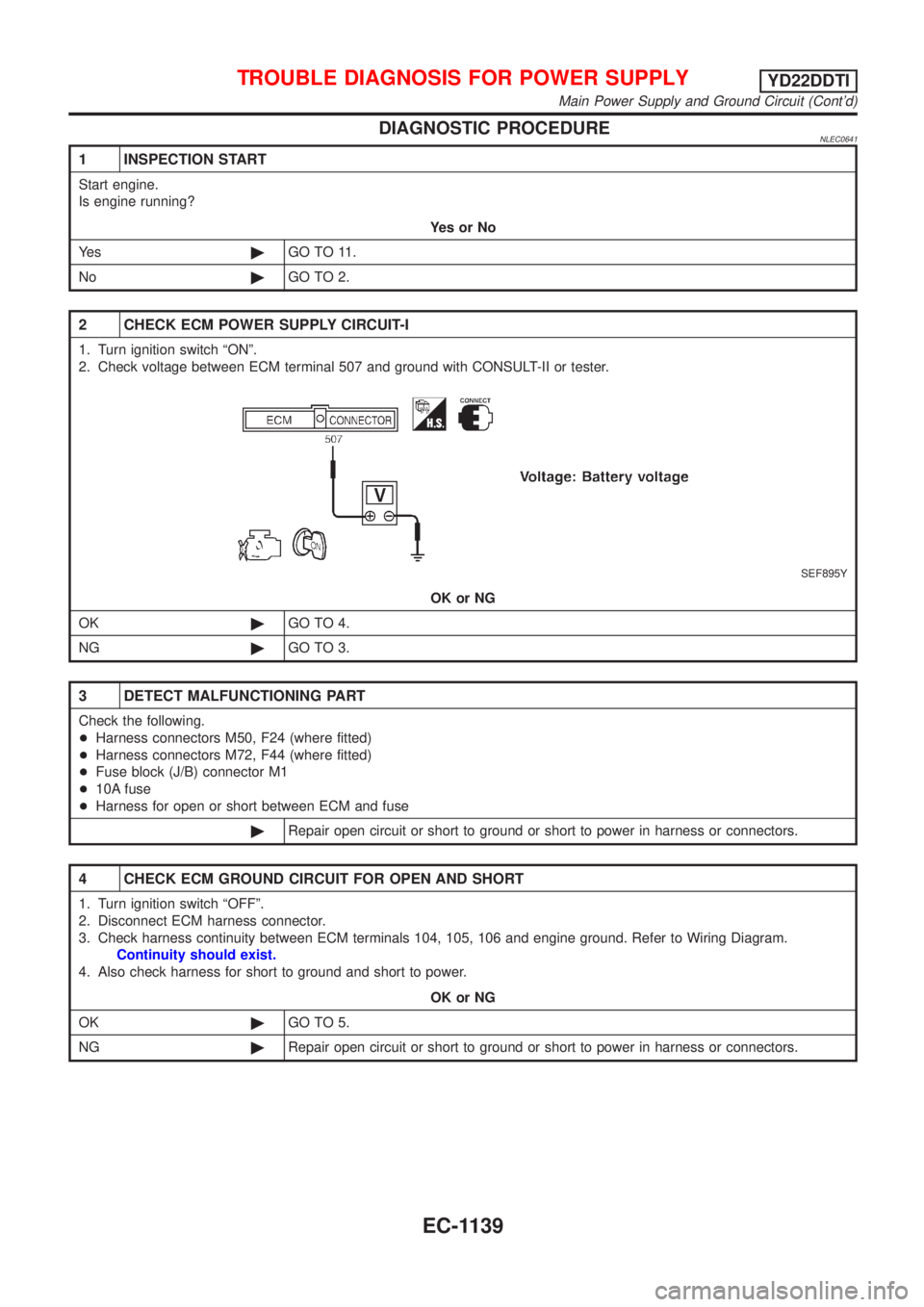
2 CHECK ECM POWER SUPPLY CIRCUIT-I
1. Turn ignition switch ªONº.
2. Check voltage between ECM terminal 507 and ground with CONSULT-II or tester.
SEF895Y
OK or NG
OK©GO TO 4.
NG©GO TO 3.
3 DETECT MALFUNCTIONING PART
Check the following.
+Harness connectors M50, F24 (where fitted)
+Harness connectors M72, F44 (where fitted)
+Fuse block (J/B) connector M1
+10A fuse
+Harness for open or short between ECM and fuse
©Repair open circuit or short to ground or short to power in harness or connectors.
4 CHECK ECM GROUND CIRCUIT FOR OPEN AND SHORT
1. Turn ignition switch ªOFFº.
2. Disconnect ECM harness connector.
3. Check harness continuity between ECM terminals 104, 105, 106 and engine ground. Refer to Wiring Diagram.
Continuity should exist.
4. Also check harness for short to ground and short to power.
OK or NG
OK©GO TO 5.
NG©Repair open circuit or short to ground or short to power in harness or connectors.
TROUBLE DIAGNOSIS FOR POWER SUPPLYYD22DDTI
Main Power Supply and Ground Circuit (Cont'd)
EC-1139
Page 1629 of 3051
Wiring DiagramNLEC0665MODELS WITH FUSE AND FUSIBLE LINK BOX E43NLEC0665S03
YEC725
DTC P1217 OVER HEATYD22DDTI
Wiring Diagram
EC-1204
Page 1630 of 3051
MODELS WITH FUSE AND FUSIBLE LINK BOX E90NLEC0665S04
YEC863
DTC P1217 OVER HEATYD22DDTI
Wiring Diagram (Cont'd)
EC-1205
Page 1637 of 3051
2 DETECT MALFUNCTIONING PART
Check the following.
+Fuse block (J/B) connector E109
+10A fuse
+40A fusible link
+Harness for open or short between cooling fan relay-1 and fuse
+Harness for open or short between cooling fan relay-1 and battery
©Repair open circuit or short to ground or short to power in harness or connectors.
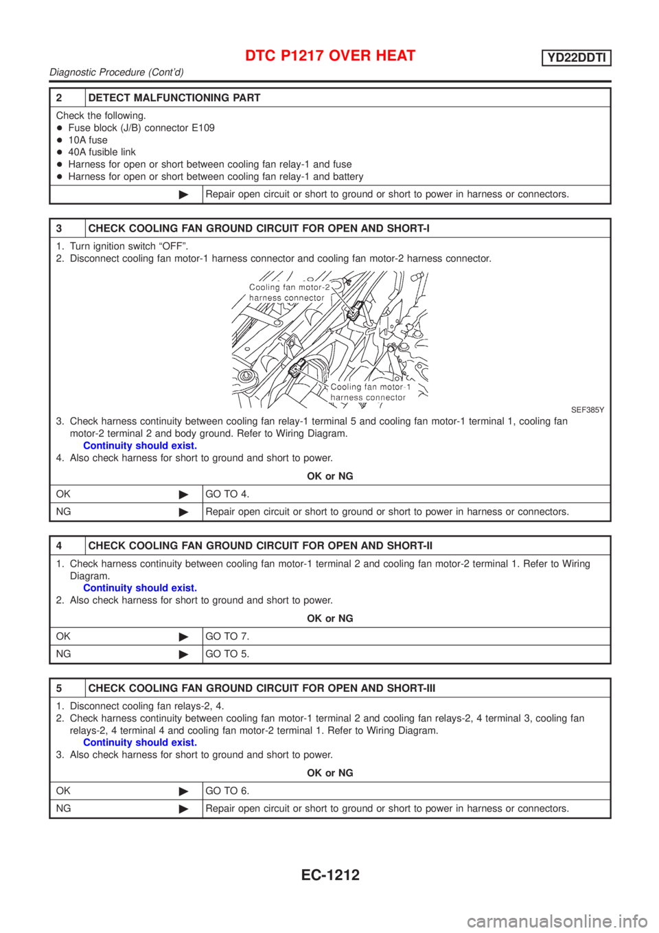
3 CHECK COOLING FAN GROUND CIRCUIT FOR OPEN AND SHORT-I
1. Turn ignition switch ªOFFº.
2. Disconnect cooling fan motor-1 harness connector and cooling fan motor-2 harness connector.
SEF385Y
3. Check harness continuity between cooling fan relay-1 terminal 5 and cooling fan motor-1 terminal 1, cooling fan
motor-2 terminal 2 and body ground. Refer to Wiring Diagram.
Continuity should exist.
4. Also check harness for short to ground and short to power.
OK or NG
OK©GO TO 4.
NG©Repair open circuit or short to ground or short to power in harness or connectors.
4 CHECK COOLING FAN GROUND CIRCUIT FOR OPEN AND SHORT-II
1. Check harness continuity between cooling fan motor-1 terminal 2 and cooling fan motor-2 terminal 1. Refer to Wiring
Diagram.
Continuity should exist.
2. Also check harness for short to ground and short to power.
OK or NG
OK©GO TO 7.
NG©GO TO 5.
5 CHECK COOLING FAN GROUND CIRCUIT FOR OPEN AND SHORT-III
1. Disconnect cooling fan relays-2, 4.
2. Check harness continuity between cooling fan motor-1 terminal 2 and cooling fan relays-2, 4 terminal 3, cooling fan
relays-2, 4 terminal 4 and cooling fan motor-2 terminal 1. Refer to Wiring Diagram.
Continuity should exist.
3. Also check harness for short to ground and short to power.
OK or NG
OK©GO TO 6.
NG©Repair open circuit or short to ground or short to power in harness or connectors.
DTC P1217 OVER HEATYD22DDTI
Diagnostic Procedure (Cont'd)
EC-1212
Page 1640 of 3051
2 DETECT MALFUNCTIONING PART
Check the following.
+40A fusible link
+Harness for open or short between cooling fan relays-2, 3, 4 and fuse
+Harness for open or short between cooling fan relay-3 and fusible link
©Repair harness or connectors.
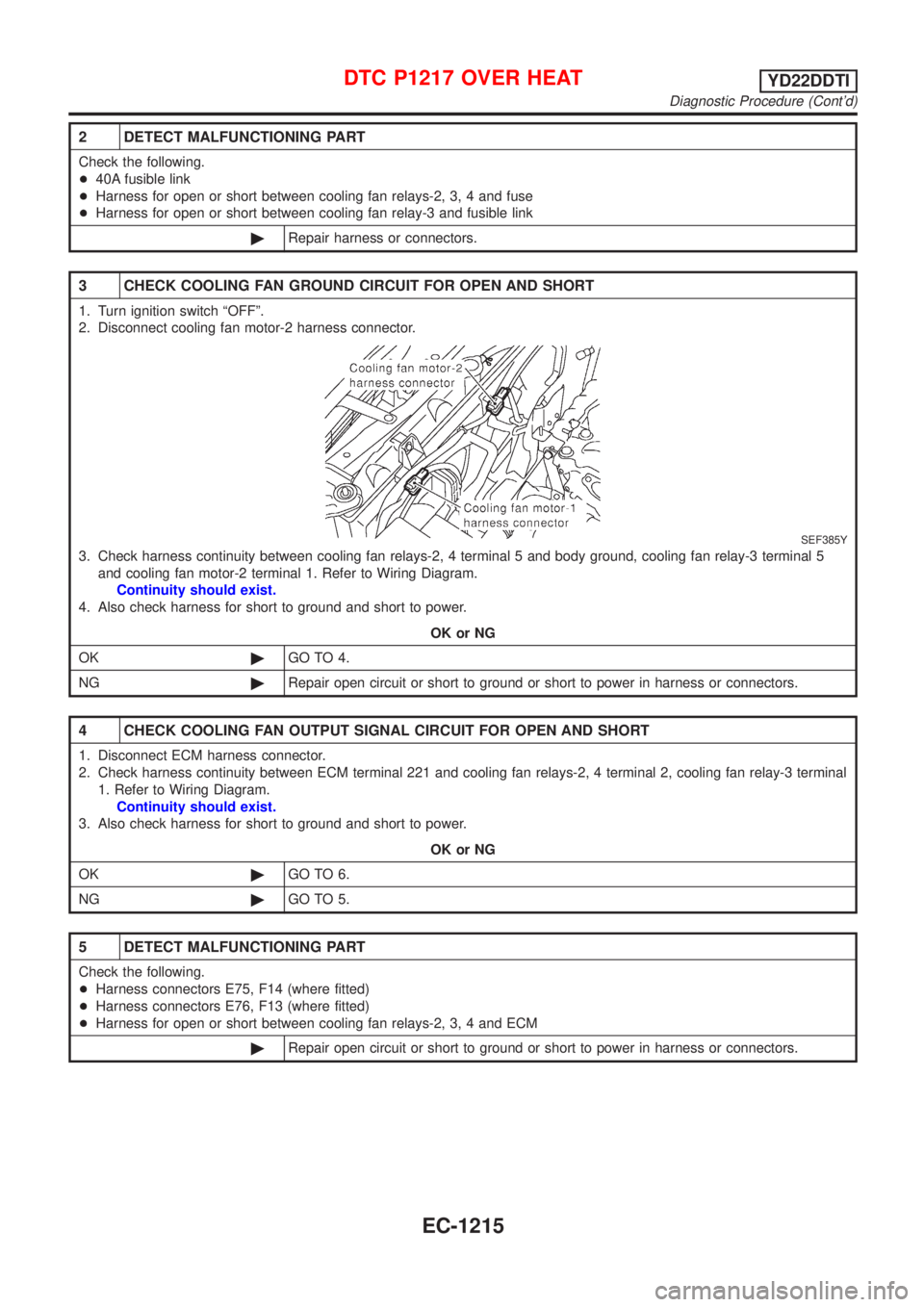
3 CHECK COOLING FAN GROUND CIRCUIT FOR OPEN AND SHORT
1. Turn ignition switch ªOFFº.
2. Disconnect cooling fan motor-2 harness connector.
SEF385Y
3. Check harness continuity between cooling fan relays-2, 4 terminal 5 and body ground, cooling fan relay-3 terminal 5
and cooling fan motor-2 terminal 1. Refer to Wiring Diagram.
Continuity should exist.
4. Also check harness for short to ground and short to power.
OK or NG
OK©GO TO 4.
NG©Repair open circuit or short to ground or short to power in harness or connectors.
4 CHECK COOLING FAN OUTPUT SIGNAL CIRCUIT FOR OPEN AND SHORT
1. Disconnect ECM harness connector.
2. Check harness continuity between ECM terminal 221 and cooling fan relays-2, 4 terminal 2, cooling fan relay-3 terminal
1. Refer to Wiring Diagram.
Continuity should exist.
3. Also check harness for short to ground and short to power.
OK or NG
OK©GO TO 6.
NG©GO TO 5.
5 DETECT MALFUNCTIONING PART
Check the following.
+Harness connectors E75, F14 (where fitted)
+Harness connectors E76, F13 (where fitted)
+Harness for open or short between cooling fan relays-2, 3, 4 and ECM
©Repair open circuit or short to ground or short to power in harness or connectors.
DTC P1217 OVER HEATYD22DDTI
Diagnostic Procedure (Cont'd)
EC-1215