Page 235 of 3051
SRA711A
1. Remove brake caliper assembly.
2. Remove wheel bearing lock nut.
3. Remove brake rotor (models with disk brake) or brake drum
(models with drum brakes).
4. Remove wheel hub bearing from spindle.
CAUTION:
Do not disconnect brake hose from caliper.
+Suspend caliper assembly with wire so as not to stretch
brake hose.
+Be careful not to depress brake pedal, or piston will pop
out.
Make sure brake hose is not twisted.
ARA082
5. Remove the sensor rotor using suitable puller, drift and bea
ring replacer.
SAX014
INSTALLATIONNLAX0030+With vehicles equipped with ABS, press-fit ABS sensor rotor
into wheel hub bearing using a drift.
Do not reuse ABS sensor rotor. When installing, replace it
with a new one.
SRA734AB
+Press-fit ABS sensor rotor as far as the location shown in fig-
ure at left.
Height“h”:
12.5 - 13.5 mm (0.492 - 0.531 in)
REAR AXLE
Wheel Hub (Cont’d)
AX-24
Page 248 of 3051
Removal and InstallationNLBR0015
NBR359
SBR997
InspectionNLBR0016Check brake pedal for following items.
+Brake pedal bend
+Clevis pin deformation
+Crack of any welded portion
+Crack or deformation of clevis pin stopper
SBR657EA
AdjustmentNLBR0017Check brake pedal free height from metal panel. Adjust if neces-
sary.
H: Free height
Refer to SDS, BR-93.
C
1,C2: Clearance between pedal stopper and threaded
end of stop lamp switch and brake switch.
0.75 - 2.00 mm (0.0295 - 0.0787 in)
D: Depressed height
LHD/RHD (M/T): 60 -70 (2.36 - 2.76 in)
LHD/RHD (CVT): 69 -79 (2.72 - 3.11 in)
Under force of 490 N (50 kg, 110 lb) with engine run-
ning.
A: Pedal free play at pedal pad
1.0 - 3.0 mm (0.039 - 0.118 in)
BRAKE PEDAL AND BRACKET
Removal and Installation
BR-11
Page 249 of 3051
SBR229E
1. Loosen lock nut and adjust pedal free height by turning brake
booster input rod. Then tighten lock nut.
2. Check pedal free play.
Make sure that stop lamps go off when pedal is released.
3. Check brake pedal’s depressed height while engine is running.
If lower than specification, check brake system for leaks, accu-
mulation of air or any damage to components (master cylinder,
wheel cylinder, etc.), then make necessary repairs.
BRAKE PEDAL AND BRACKET
Adjustment (Cont’d)
BR-12
Page 330 of 3051

General SpecificationsNLBR0077Unit: mm (in)
EngineQG18DE, SR20DE YD22DDTi
Front BrakeBrake model CL25VCG
Cylinder bore diameter 57.2 (2.2529)
Pad
Length×width×thickness110.6×54.2×11.0 (4.35×2.13×0.433)
Rotor outer
diameter×thickness280×28 (11.02×1.10)
Rear BrakeBrake model CL11HDG (disc brake)
Cylinder bore diam-
eterCam & Strut type 38 (1.496)
Ball & Ramp type 38.2 (1.504)
Pad
Length×width×thickness79.8×38.5×9.3 (3.142×1.516×0.37)
Rotor outer diameter×thickness 278×10 (10.94×0.39)
Master cylinder Cylinder bore diameter 23.81 (15/16)
Brake boosterBooster model S255 M215T S255
DiaphragmPrimary 255 (10.04) 230 (9.06) 255 (10.04)
Secondary—205 (8.07)—
Specified brake fluidDOT 4
Disc BrakeNLBR0078Unit: mm (in)
Brake modelCL25VCG CL11HDG
Pad wear limit Minimum thickness 2.0 (0.078) 2.0 (0.079)
Rotor repair limitMaximum runout 0.07 (0.0028) 0.07 (0.0028)
Minimum thickness 26.0 (1.024) 9 (0.35)
Brake PedalNLBR0079Unit: mm (in)
Free height“H”*LHDM/T 154.8 - 164.8 (6.09 - 6.49)
CVT 164 - 174 (6.46 - 6.85)
RHDM/T 154.8 - 164.8 (6.09 - 6.49)
CVT 164 - 174 (6.46 - 6.85)
Clearance“C”between pedal stopper and threaded end of stop lamp switch or brake switch 0.75 - 2.00 (0.0295 - 0.0787)
*: Measured from surface of dash panel to surface of pedal pad
Parking BrakeNLBR0080
TypeCenter lever
Number of notches
[under force of 196 N (20 kg, 44 lb)]5-6
Number of notches
when warning lamp switch comes on1
SERVICE DATA AND SPECIFICATIONS (SDS)
General Specifications
BR-93
Page 387 of 3051
ADJUSTMENTNLBT0022S03
NBT150
If any height difference between glass lid and roof is found, check
glass lid fit and adjust as follows:
Height Difference AdjustmentNLBT0022S03021. Tilt glass lid up and down.
2. Check height difference between roof panel and glass lid to
see if it is as ªA-Aº as shown in the figure above.
3. If necessary, adjust it by using one of following procedures.
+Adjust by adding or removing adjustment shim(s) between
glass lid and link assembly.
+If glass lid protrudes above roof panel, add shim(s) or plain
washer(s) at sunroof mounting bracket or stud bolt locations to
adjust sunroof installation as required.
SUNROOF
Trouble Diagnoses (Cont'd)
BT-56
Page 425 of 3051

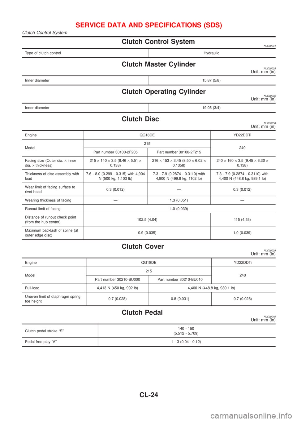
Clutch Control SystemNLCL0034
Type of clutch controlHydraulic
Clutch Master CylinderNLCL0035Unit: mm (in)
Inner diameter15.87 (5/8)
Clutch Operating CylinderNLCL0036Unit: mm (in)
Inner diameter19.05 (3/4)
Clutch DiscNLCL0038Unit: mm (in)
Engine QG18DE YD22DDTi
Model215
240
Part number 30100-2F205 Part number 30100-2F215
Facing size (Outer dia.´inner
dia.´thickness)215´140´3.5 (8.46´5.51´
0.138)216´153´3.45 (8.50´6.02´
0.1358)240´160´3.5 (9.45´6.30´
0.138)
Thickness of disc assembly with
load7.6 - 8.0 (0.299 - 0.315) with 4,904
N (500 kg, 1,103 lb)7.3 - 7.9 (0.2874 - 0.3110) with
4,900 N (499.8 kg, 1102 lb)7.3 - 7.9 (0.2874 - 0.3110) with
4,400 N (448.8 kg, 989.1 lb)
Wear limit of facing surface to
rivet head0.3 (0.012) Ð 0.3 (0.012)
Wearing thickness of facing Ð 1.3 (0.051) Ð
Runout limit of facing 1.0 (0.039)
Distance of runout check point
(from the hub center)102.5 (4.04) 115 (4.53)
Maximum backlash of spline (at
outer edge disc)0.9 (0.035) 1.0 (0.039)
Clutch CoverNLCL0039Unit: mm (in)
Engine QG18DE YD22DDTi
Model215
240
Part number 30210-BU000 Part number 30210-BU010
Full-load 4,413 N (450 kg, 992 lb) 4,400 N (448.8 kg, 989.1 lb)
Uneven limit of diaphragm spring
toe height0.7 (0.028) 0.8 (0.031) 0.7 (0.028)
Clutch PedalNLCL0040Unit: mm (in)
Clutch pedal stroke ªSº140 - 150
(5.512 - 5.709)
Pedal free play ªAº1 - 3 (0.04 - 0.12)
SERVICE DATA AND SPECIFICATIONS (SDS)
Clutch Control System
CL-24
Page 615 of 3051

SEF646Y
SEF647Y
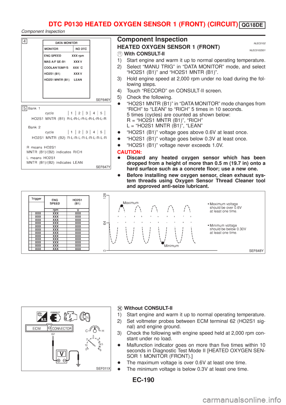
Component InspectionNLEC0102HEATED OXYGEN SENSOR 1 (FRONT)NLEC0102S01With CONSULT-II
1) Start engine and warm it up to normal operating temperature.
2) Select ªMANU TRIGº in ªDATA MONITORº mode, and select
ªHO2S1 (B1)º and ªHO2S1 MNTR (B1)º.
3) Hold engine speed at 2,000 rpm under no load during the fol-
lowing steps.
4) Touch ªRECORDº on CONSULT-II screen.
5) Check the following.
+ªHO2S1 MNTR (B1)º in ªDATA MONITORº mode changes from
ªRICHº to ªLEANº to ªRICHº 5 times in 10 seconds.
5 times (cycles) are counted as shown below:
R = ªHO2S1 MNTR (B1)º, ªRICHº
L = ªHO2S1 MNTR (B1)º, ªLEANº
+ªHO2S1 (B1)º voltage goes above 0.6V at least once.
+ªHO2S1 (B1)º voltage goes below 0.3V at least once.
+ªHO2S1 (B1)º voltage never exceeds 1.0V.
CAUTION:
+Discard any heated oxygen sensor which has been
dropped from a height of more than 0.5 m (19.7 in) onto a
hard surface such as a concrete floor; use a new one.
+Before installing new oxygen sensor, clean exhaust sys-
tem threads using Oxygen Sensor Thread Cleaner tool
and approved anti-seize lubricant.
SEF648Y
SEF011X
Without CONSULT-II
1) Start engine and warm it up to normal operating temperature.
2) Set voltmeter probes between ECM terminal 62 (HO2S1 sig-
nal) and engine ground.
3) Check the following with engine speed held at 2,000 rpm con-
stant under no load.
+Malfunction indicator goes on more than five times within 10
seconds in Diagnostic Test Mode II [HEATED OXYGEN SEN-
SOR 1 MONITOR (FRONT).]
+The maximum voltage is over 0.6V at least one time.
+The minimum voltage is below 0.3V at least one time.
DTC P0130 HEATED OXYGEN SENSOR 1 (FRONT) (CIRCUIT)QG18DE
Component Inspection
EC-190
Page 616 of 3051
+The voltage never exceeds 1.0V.
CAUTION:
+Discard any heated oxygen sensor which has been
dropped from a height of more than 0.5 m (19.7 in) onto a
hard surface such as a concrete floor; use a new one.
+Before installing new oxygen sensor, clean exhaust sys-
tem threads using Oxygen Sensor Thread Cleaner tool
and approved anti-seize lubricant.
DTC P0130 HEATED OXYGEN SENSOR 1 (FRONT) (CIRCUIT)QG18DE
Component Inspection (Cont'd)
EC-191