Page 845 of 3051
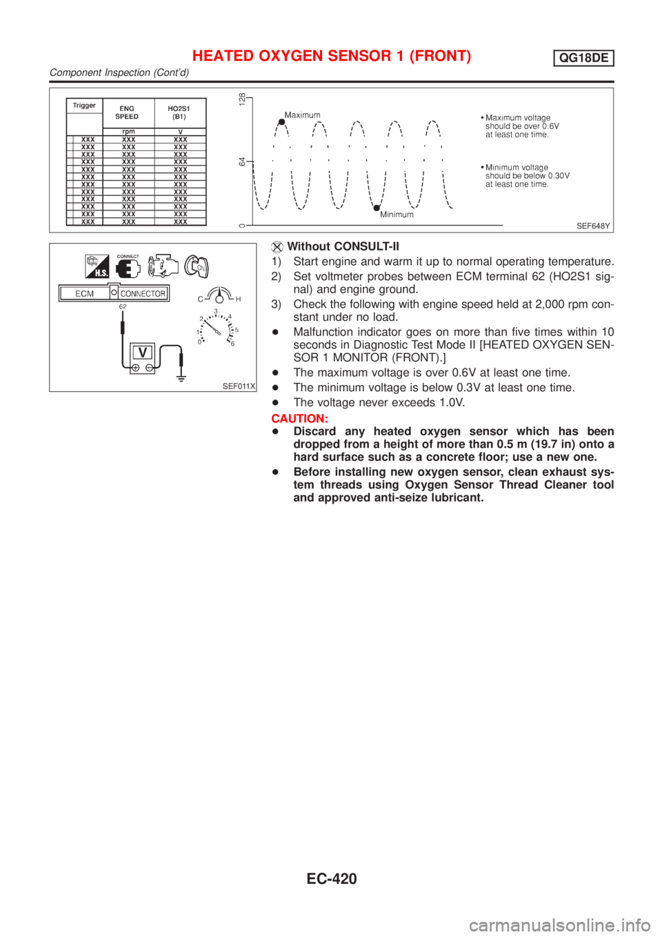
SEF648Y
SEF011X
Without CONSULT-II
1) Start engine and warm it up to normal operating temperature.
2) Set voltmeter probes between ECM terminal 62 (HO2S1 sig-
nal) and engine ground.
3) Check the following with engine speed held at 2,000 rpm con-
stant under no load.
+Malfunction indicator goes on more than five times within 10
seconds in Diagnostic Test Mode II [HEATED OXYGEN SEN-
SOR 1 MONITOR (FRONT).]
+The maximum voltage is over 0.6V at least one time.
+The minimum voltage is below 0.3V at least one time.
+The voltage never exceeds 1.0V.
CAUTION:
+Discard any heated oxygen sensor which has been
dropped from a height of more than 0.5 m (19.7 in) onto a
hard surface such as a concrete floor; use a new one.
+Before installing new oxygen sensor, clean exhaust sys-
tem threads using Oxygen Sensor Thread Cleaner tool
and approved anti-seize lubricant.
HEATED OXYGEN SENSOR 1 (FRONT)QG18DE
Component Inspection (Cont'd)
EC-420
Page 850 of 3051
3 DETECT MALFUNCTIONING PART
Check the following.
+Harness connectors F38, M50 (where fitted)
+Harness connectors M72, F44 (where fitted)
+10A fuse
+Harness for open or short between heated oxygen sensor 1 (front) and fuse
©Repair harness or connectors.
4 CHECK OUTPUT SIGNAL CIRCUIT
1. Turn ignition switch ªOFFº.
2. Disconnect ECM harness connector.
3. Check harness continuity between heated oxygen sensor 1 (front) harness connector terminal 3 and ECM terminal 4.
Refer to wiring diagram.
Continuity should exist.
4. Also check harness for short to ground and short to power.
OK or NG
OK©GO TO 5.
NG©Repair open circuit or short to ground or short to power in harness or connectors.
5 CHECK HEATED OXYGEN SENSOR 1 HEATER (FRONT)
Refer to ªComponent Inspectionº, EC-425.
OK or NG
OK©GO TO 6.
NG©Replace heated oxygen sensor 1 (front).
6 CHECK INTERMITTENT INCIDENT
Perform ªTROUBLE DIAGNOSIS FOR INTERMITTENT INCIDENTº, EC-145.
©INSPECTION END
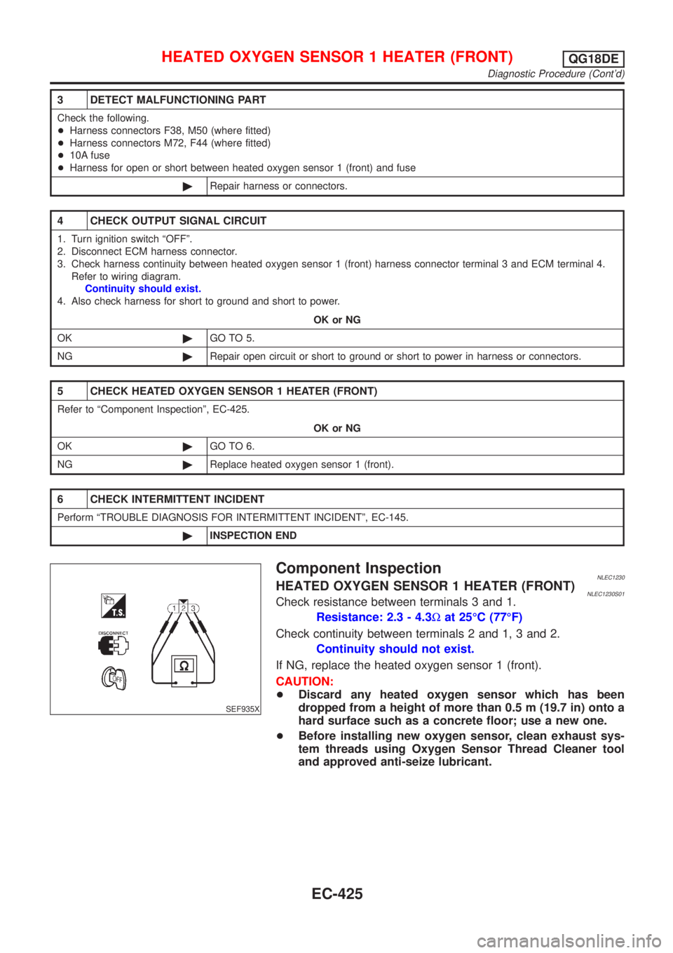
SEF935X
Component InspectionNLEC1230HEATED OXYGEN SENSOR 1 HEATER (FRONT)NLEC1230S01Check resistance between terminals 3 and 1.
Resistance: 2.3 - 4.3Wat 25ÉC (77ÉF)
Check continuity between terminals 2 and 1, 3 and 2.
Continuity should not exist.
If NG, replace the heated oxygen sensor 1 (front).
CAUTION:
+Discard any heated oxygen sensor which has been
dropped from a height of more than 0.5 m (19.7 in) onto a
hard surface such as a concrete floor; use a new one.
+Before installing new oxygen sensor, clean exhaust sys-
tem threads using Oxygen Sensor Thread Cleaner tool
and approved anti-seize lubricant.
HEATED OXYGEN SENSOR 1 HEATER (FRONT)QG18DE
Diagnostic Procedure (Cont'd)
EC-425
Page 856 of 3051
6 CHECK GROUND CIRCUIT
1. Check harness continuity between heated oxygen sensor 2 (rear) harness connector terminal 4 and body ground.
Refer to wiring diagram.
Continuity should exist.
2. Also check harness for short to power.
OK or NG
OK©GO TO 7.
NG©Repair open circuit or short to power in harness or connectors.
7 CHECK HEATED OXYGEN SENSOR 2 (REAR)
Refer to ªComponent Inspectionº, EC-431.
OK or NG
OK©GO TO 8.
NG©Replace heated oxygen sensor 2 (rear).
8 CHECK INTERMITTENT INCIDENT
Perform ªTROUBLE DIAGNOSIS FOR INTERMITTENT INCIDENTº, EC-145.
©INSPECTION END
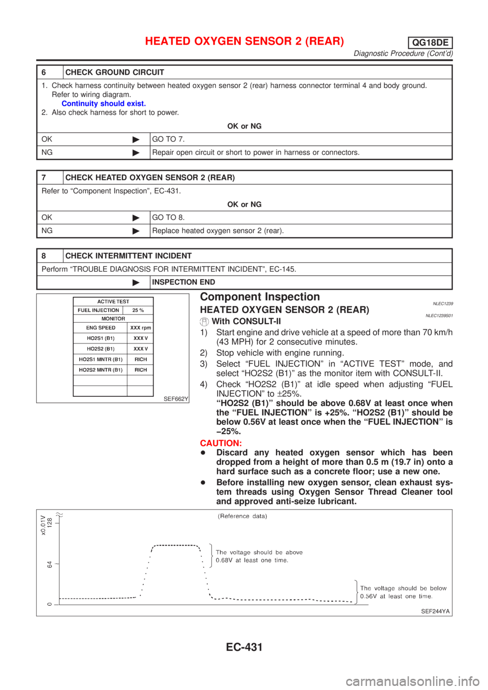
SEF662Y
Component InspectionNLEC1239HEATED OXYGEN SENSOR 2 (REAR)NLEC1239S01With CONSULT-II
1) Start engine and drive vehicle at a speed of more than 70 km/h
(43 MPH) for 2 consecutive minutes.
2) Stop vehicle with engine running.
3) Select ªFUEL INJECTIONº in ªACTIVE TESTº mode, and
select ªHO2S2 (B1)º as the monitor item with CONSULT-II.
4) Check ªHO2S2 (B1)º at idle speed when adjusting ªFUEL
INJECTIONº to±25%.
ªHO2S2 (B1)º should be above 0.68V at least once when
the ªFUEL INJECTIONº is +25%. ªHO2S2 (B1)º should be
below 0.56V at least once when the ªFUEL INJECTIONº is
þ25%.
CAUTION:
+Discard any heated oxygen sensor which has been
dropped from a height of more than 0.5 m (19.7 in) onto a
hard surface such as a concrete floor; use a new one.
+Before installing new oxygen sensor, clean exhaust sys-
tem threads using Oxygen Sensor Thread Cleaner tool
and approved anti-seize lubricant.
SEF244YA
HEATED OXYGEN SENSOR 2 (REAR)QG18DE
Diagnostic Procedure (Cont'd)
EC-431
Page 857 of 3051
SEF032X
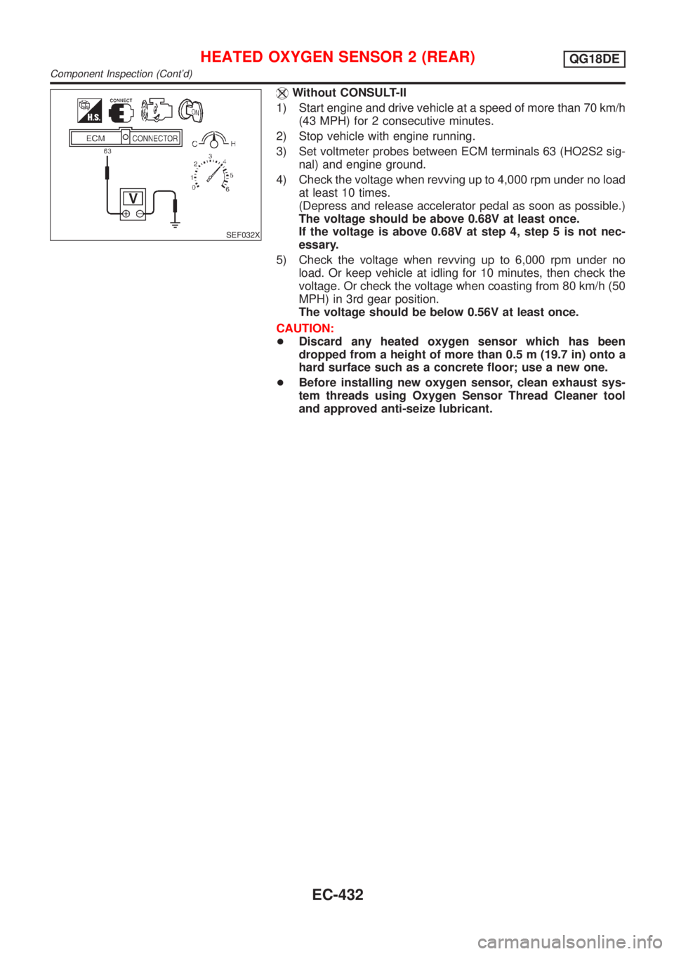
Without CONSULT-II
1) Start engine and drive vehicle at a speed of more than 70 km/h
(43 MPH) for 2 consecutive minutes.
2) Stop vehicle with engine running.
3) Set voltmeter probes between ECM terminals 63 (HO2S2 sig-
nal) and engine ground.
4) Check the voltage when revving up to 4,000 rpm under no load
at least 10 times.
(Depress and release accelerator pedal as soon as possible.)
The voltage should be above 0.68V at least once.
If the voltage is above 0.68V at step 4, step 5 is not nec-
essary.
5) Check the voltage when revving up to 6,000 rpm under no
load. Or keep vehicle at idling for 10 minutes, then check the
voltage. Or check the voltage when coasting from 80 km/h (50
MPH) in 3rd gear position.
The voltage should be below 0.56V at least once.
CAUTION:
+Discard any heated oxygen sensor which has been
dropped from a height of more than 0.5 m (19.7 in) onto a
hard surface such as a concrete floor; use a new one.
+Before installing new oxygen sensor, clean exhaust sys-
tem threads using Oxygen Sensor Thread Cleaner tool
and approved anti-seize lubricant.
HEATED OXYGEN SENSOR 2 (REAR)QG18DE
Component Inspection (Cont'd)
EC-432
Page 863 of 3051
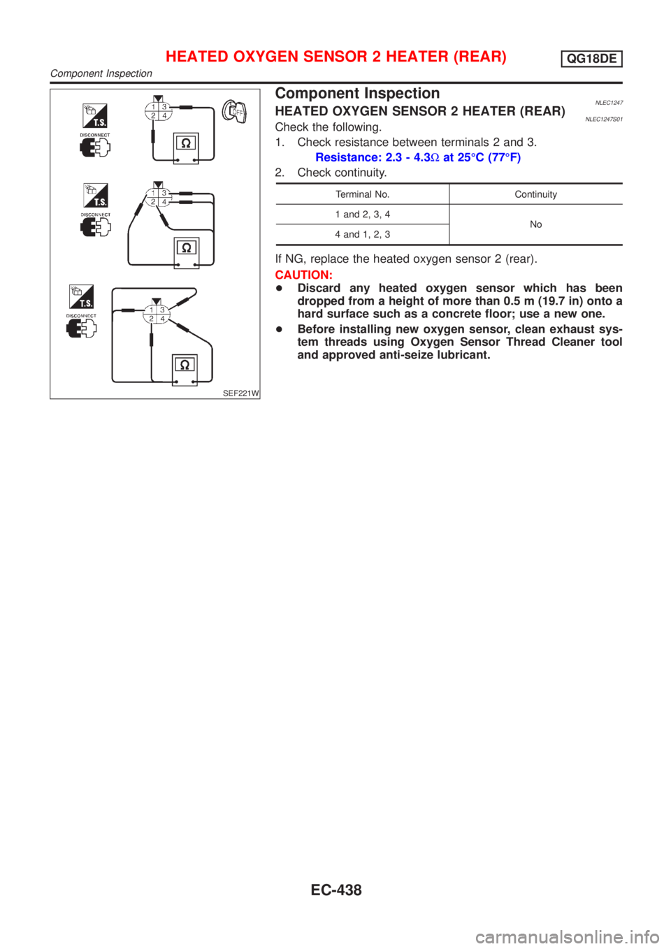
SEF221W
Component InspectionNLEC1247HEATED OXYGEN SENSOR 2 HEATER (REAR)NLEC1247S01Check the following.
1. Check resistance between terminals 2 and 3.
Resistance: 2.3 - 4.3Wat 25ÉC (77ÉF)
2. Check continuity.
Terminal No. Continuity
1 and 2, 3, 4
No
4 and 1, 2, 3
If NG, replace the heated oxygen sensor 2 (rear).
CAUTION:
+Discard any heated oxygen sensor which has been
dropped from a height of more than 0.5 m (19.7 in) onto a
hard surface such as a concrete floor; use a new one.
+Before installing new oxygen sensor, clean exhaust sys-
tem threads using Oxygen Sensor Thread Cleaner tool
and approved anti-seize lubricant.
HEATED OXYGEN SENSOR 2 HEATER (REAR)QG18DE
Component Inspection
EC-438
Page 1140 of 3051
SEF646Y
SEF217YA
Component InspectionNLEC1421HEATED OXYGEN SENSOR 1 (FRONT)NLEC1421S01With CONSULT-II
1) Start engine and warm it up to normal operating temperature.
2) Select ªMANU TRIGº in ªDATA MONITORº mode, and select
ªHO2S1 (B1)º and ªHO2S1 MNTR (B1)º.
3) Hold engine speed at 2,000 rpm under no load during the fol-
lowing steps.
4) Touch ªRECORDº on CONSULT-II screen.
5) Check the following.
+ªHO2S1 MNTR (B1)º in ªDATA MONITORº mode changes from
ªRICHº to ªLEANº to ªRICHº 5 times in 10 seconds.
5 times (cycles) are counted as shown below:
R = ªHO2S1 MNTR (B1)º, ªRICHº
L = ªHO2S1 MNTR (B1)º, ªLEANº
+ªHO2S1 (B1)º voltage goes above 0.6V at least once.
+ªHO2S1 (B1)º voltage goes below 0.3V at least once.
+ªHO2S1 (B1)º voltage never exceeds 1.0V.
CAUTION:
+Discard any heated oxygen sensor which has been
dropped from a height of more than 0.5 m (19.7 in) onto a
hard surface such as a concrete floor; use a new one.
+Before installing new oxygen sensor, clean exhaust sys-
tem threads using Oxygen Sensor Thread Cleaner tool
and approved anti-seize lubricant.
SEF648Y
SEF011X
Without CONSULT-II
1) Start engine and warm it up to normal operating temperature.
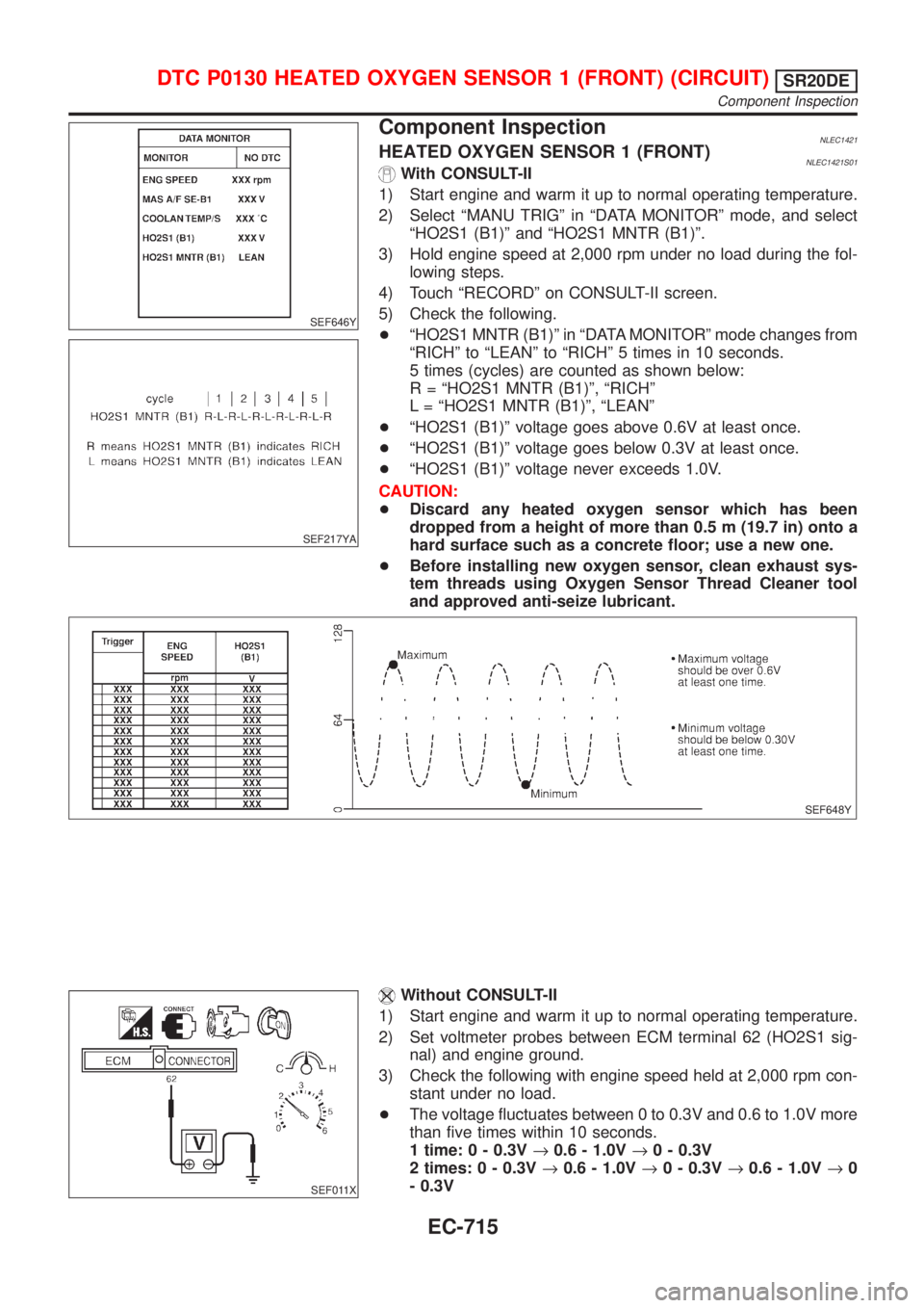
2) Set voltmeter probes between ECM terminal 62 (HO2S1 sig-
nal) and engine ground.
3) Check the following with engine speed held at 2,000 rpm con-
stant under no load.
+The voltage fluctuates between 0 to 0.3V and 0.6 to 1.0V more
than five times within 10 seconds.
1 time: 0 - 0.3V®0.6 - 1.0V®0 - 0.3V
2 times: 0 - 0.3V®0.6 - 1.0V®0 - 0.3V®0.6 - 1.0V®0
- 0.3V
DTC P0130 HEATED OXYGEN SENSOR 1 (FRONT) (CIRCUIT)SR20DE
Component Inspection
EC-715
Page 1141 of 3051
+The maximum voltage is over 0.6V at least one time.
+The minimum voltage is below 0.3V at least one time.
+The voltage never exceeds 1.0V.
CAUTION:
+Discard any heated oxygen sensor which has been
dropped from a height of more than 0.5 m (19.7 in) onto a
hard surface such as a concrete floor; use a new one.
+Before installing new oxygen sensor, clean exhaust sys-
tem threads using Oxygen Sensor Thread Cleaner tool
and approved anti-seize lubricant.
DTC P0130 HEATED OXYGEN SENSOR 1 (FRONT) (CIRCUIT)SR20DE
Component Inspection (Cont'd)
EC-716
Page 1146 of 3051
4 CHECK HEATED OXYGEN SENSOR 1 (FRONT)
Refer to ªComponent Inspectionº, EC-721.
OK or NG
OK©GO TO 5.
NG©Replace heated oxygen sensor 1 (front).
5 CHECK INTERMITTENT INCIDENT
Perform ªTROUBLE DIAGNOSIS FOR INTERMITTENT INCIDENTº, EC-670.
Refer to ªWiring Diagramº, EC-712, for circuit.
©INSPECTION END
SEF646Y
SEF217YA
Component InspectionNLEC1429HEATED OXYGEN SENSOR 1 (FRONT)NLEC1429S01With CONSULT-II
1) Start engine and warm it up to normal operating temperature.
2) Select ªMANU TRIGº in ªDATA MONITORº mode, and select
ªHO2S1 (B1)º and ªHO2S1 MNTR (B1)º.
3) Hold engine speed at 2,000 rpm under no load during the fol-
lowing steps.
4) Touch ªRECORDº on CONSULT-II screen.
5) Check the following.
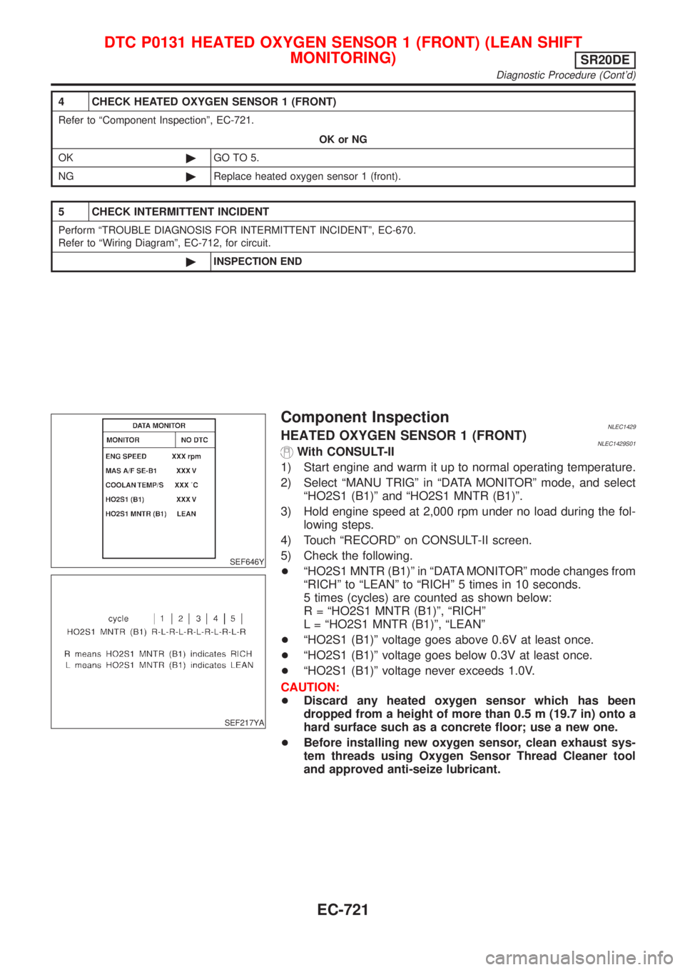
+ªHO2S1 MNTR (B1)º in ªDATA MONITORº mode changes from
ªRICHº to ªLEANº to ªRICHº 5 times in 10 seconds.
5 times (cycles) are counted as shown below:
R = ªHO2S1 MNTR (B1)º, ªRICHº
L = ªHO2S1 MNTR (B1)º, ªLEANº
+ªHO2S1 (B1)º voltage goes above 0.6V at least once.
+ªHO2S1 (B1)º voltage goes below 0.3V at least once.
+ªHO2S1 (B1)º voltage never exceeds 1.0V.
CAUTION:
+Discard any heated oxygen sensor which has been
dropped from a height of more than 0.5 m (19.7 in) onto a
hard surface such as a concrete floor; use a new one.
+Before installing new oxygen sensor, clean exhaust sys-
tem threads using Oxygen Sensor Thread Cleaner tool
and approved anti-seize lubricant.
DTC P0131 HEATED OXYGEN SENSOR 1 (FRONT) (LEAN SHIFT
MONITORING)
SR20DE
Diagnostic Procedure (Cont'd)
EC-721