2001 NISSAN ALMERA TINO accelerator control
[x] Cancel search: accelerator controlPage 1 of 3051

Release:April 2001 01)GENERALINFORMATIONGIMAINTENANCEMAENGINEMECHANICALEMENGINELUBRICATION&
COOLINGSYSTEMSLCENGINECONTROLSYSTEMECACCELERATORCONTROL,
FUEL&EXHAUSTSYSTEMSFECLUTCHCLMANUALTRANSAXLEMTAUTOMATICTRANSAXLEATFRONT&REARAXLEAXFRONT&REARSUSPENSIONSUBRAKESYSTEMBRSTEERINGSYSTEMSTRESTRAINTSYSTEMRSBODY&TRIMBTHEATER&AIRCONDITIONERHASTARTING&CHARGINGSYSTEMSSCELECTRICALSYSTEMELALPHABETICALINDEXIDXALMERATINOMODELV10SERIESQUICKREFERENCEINDEX
Page 60 of 3051
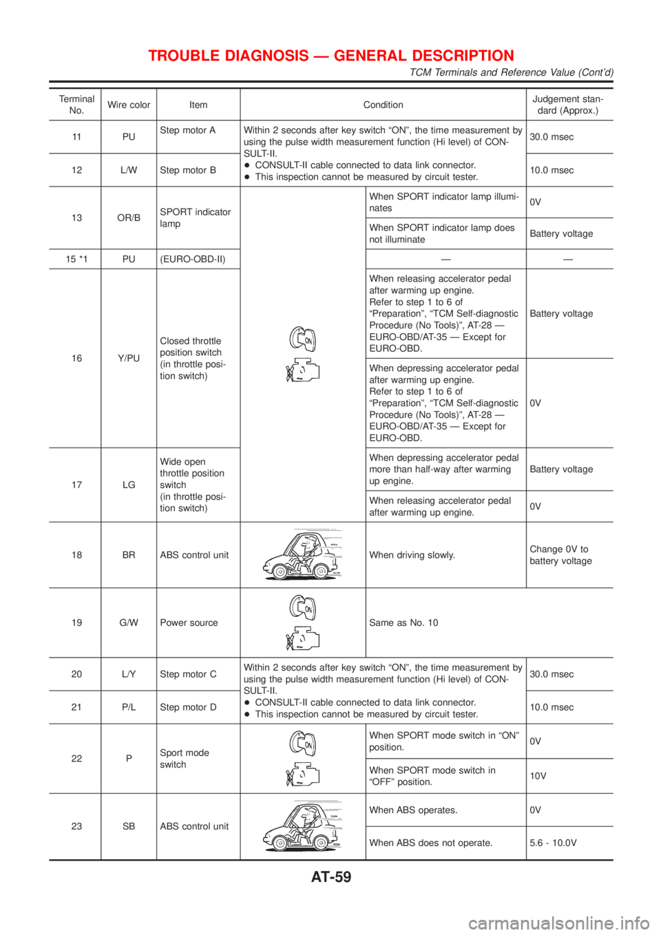
Terminal
No.Wire color Item ConditionJudgement stan-
dard (Approx.)
11 P UStep motor A Within 2 seconds after key switch ªONº, the time measurement by
using the pulse width measurement function (Hi level) of CON-
SULT-II.
+CONSULT-II cable connected to data link connector.
+This inspection cannot be measured by circuit tester.30.0 msec
12 L/W Step motor B10.0 msec
13 OR/BSPORT indicator
lamp
When SPORT indicator lamp illumi-
nates0V
When SPORT indicator lamp does
not illuminateBattery voltage
15 *1 PU (EURO-OBD-II) Ð Ð
16 Y/PUClosed throttle
position switch
(in throttle posi-
tion switch)When releasing accelerator pedal
after warming up engine.
Refer to step 1 to 6 of
ªPreparationº, ªTCM Self-diagnostic
Procedure (No Tools)º, AT-28 Ð
EURO-OBD/AT-35 Ð Except for
EURO-OBD.Battery voltage
When depressing accelerator pedal
after warming up engine.
Refer to step 1 to 6 of
ªPreparationº, ªTCM Self-diagnostic
Procedure (No Tools)º, AT-28 Ð
EURO-OBD/AT-35 Ð Except for
EURO-OBD.0V
17 LGWide open
throttle position
switch
(in throttle posi-
tion switch)When depressing accelerator pedal
more than half-way after warming
up engine.Battery voltage
When releasing accelerator pedal
after warming up engine.0V
18 BR ABS control unit
When driving slowly.Change 0V to
battery voltage
19 G/W Power source
Same as No. 10
20 L/Y Step motor CWithin 2 seconds after key switch ªONº, the time measurement by
using the pulse width measurement function (Hi level) of CON-
SULT-II.
+CONSULT-II cable connected to data link connector.
+This inspection cannot be measured by circuit tester.30.0 msec
21 P/L Step motor D10.0 msec
22 PSport mode
switch
When SPORT mode switch in ªONº
position.0V
When SPORT mode switch in
ªOFFº position.10V
23 SB ABS control unit
When ABS operates. 0V
When ABS does not operate. 5.6 - 10.0V
TROUBLE DIAGNOSIS Ð GENERAL DESCRIPTION
TCM Terminals and Reference Value (Cont'd)
AT-59
Page 95 of 3051
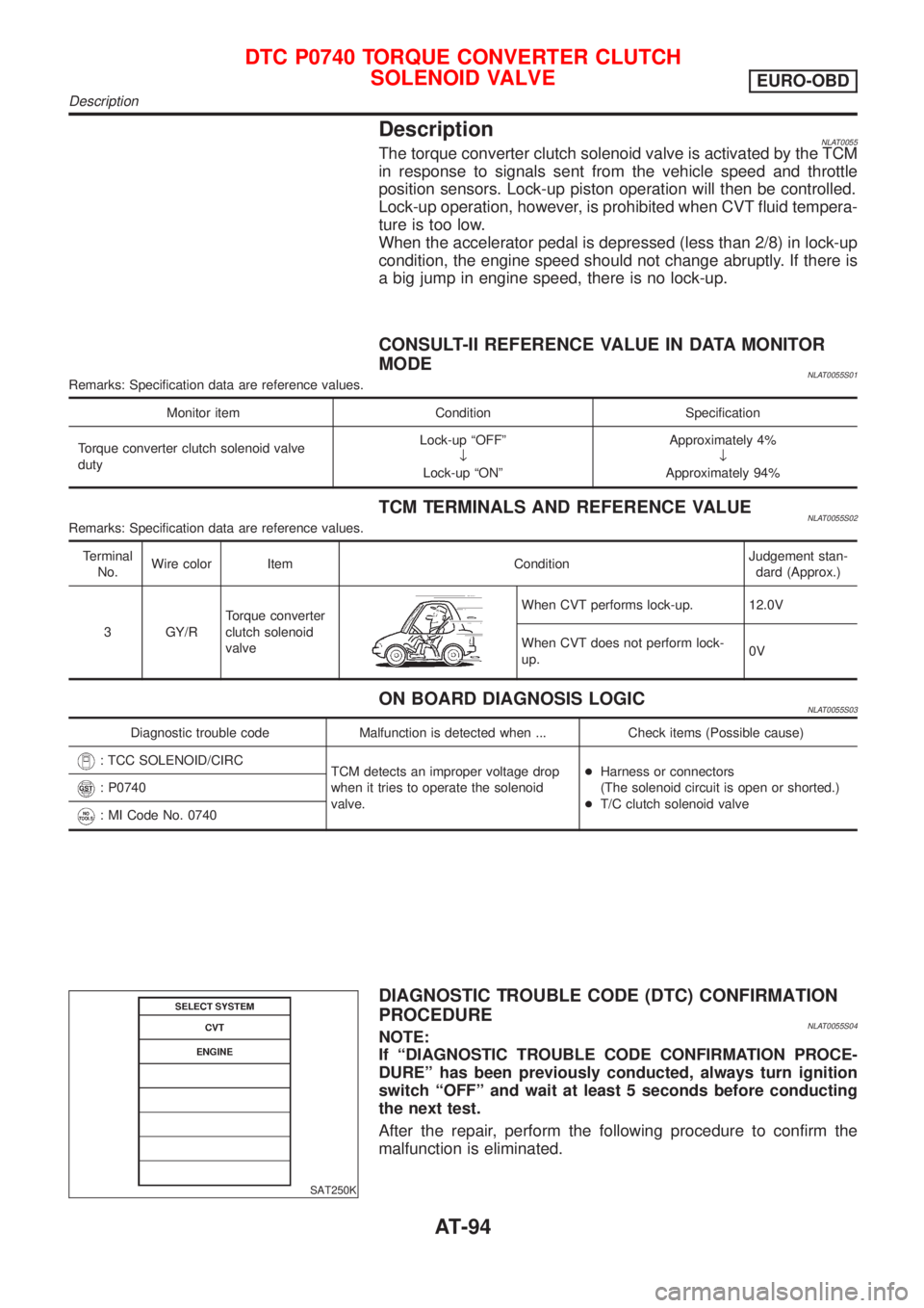
DescriptionNLAT0055The torque converter clutch solenoid valve is activated by the TCM
in response to signals sent from the vehicle speed and throttle
position sensors. Lock-up piston operation will then be controlled.
Lock-up operation, however, is prohibited when CVT fluid tempera-
ture is too low.
When the accelerator pedal is depressed (less than 2/8) in lock-up
condition, the engine speed should not change abruptly. If there is
a big jump in engine speed, there is no lock-up.
CONSULT-II REFERENCE VALUE IN DATA MONITOR
MODE
NLAT0055S01Remarks: Specification data are reference values.
Monitor item Condition Specification
Torque converter clutch solenoid valve
dutyLock-up ªOFFº
¯
Lock-up ªONºApproximately 4%
¯
Approximately 94%
TCM TERMINALS AND REFERENCE VALUENLAT0055S02Remarks: Specification data are reference values.
Terminal
No.Wire color Item ConditionJudgement stan-
dard (Approx.)
3 GY/RTorque converter
clutch solenoid
valve
When CVT performs lock-up. 12.0V
When CVT does not perform lock-
up.0V
ON BOARD DIAGNOSIS LOGICNLAT0055S03
Diagnostic trouble code Malfunction is detected when ... Check items (Possible cause)
: TCC SOLENOID/CIRC
TCM detects an improper voltage drop
when it tries to operate the solenoid
valve.+Harness or connectors
(The solenoid circuit is open or shorted.)
+T/C clutch solenoid valve
: P0740
: MI Code No. 0740
SAT250K
DIAGNOSTIC TROUBLE CODE (DTC) CONFIRMATION
PROCEDURE
NLAT0055S04NOTE:
If ªDIAGNOSTIC TROUBLE CODE CONFIRMATION PROCE-
DUREº has been previously conducted, always turn ignition
switch ªOFFº and wait at least 5 seconds before conducting
the next test.
After the repair, perform the following procedure to confirm the
malfunction is eliminated.
DTC P0740 TORQUE CONVERTER CLUTCH
SOLENOID VALVE
EURO-OBD
Description
AT-94
Page 109 of 3051
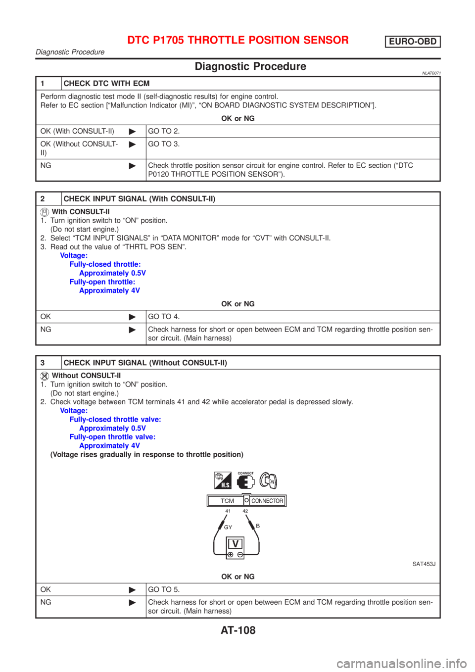
Diagnostic ProcedureNLAT0071
1 CHECK DTC WITH ECM
Perform diagnostic test mode II (self-diagnostic results) for engine control.
Refer to EC section [ªMalfunction Indicator (MI)º, ªON BOARD DIAGNOSTIC SYSTEM DESCRIPTIONº].
OK or NG
OK (With CONSULT-II)©GO TO 2.
OK (Without CONSULT-
II)©GO TO 3.
NG©Check throttle position sensor circuit for engine control. Refer to EC section (ªDTC
P0120 THROTTLE POSITION SENSORº).
2 CHECK INPUT SIGNAL (With CONSULT-II)
With CONSULT-II
1. Turn ignition switch to ªONº position.
(Do not start engine.)
2. Select ªTCM INPUT SIGNALSº in ªDATA MONITORº mode for ªCVTº with CONSULT-II.
3. Read out the value of ªTHRTL POS SENº.
Voltage:
Fully-closed throttle:
Approximately 0.5V
Fully-open throttle:
Approximately 4V
OK or NG
OK©GO TO 4.
NG©Check harness for short or open between ECM and TCM regarding throttle position sen-
sor circuit. (Main harness)
3 CHECK INPUT SIGNAL (Without CONSULT-II)
Without CONSULT-II
1. Turn ignition switch to ªONº position.
(Do not start engine.)
2. Check voltage between TCM terminals 41 and 42 while accelerator pedal is depressed slowly.
Voltage:
Fully-closed throttle valve:
Approximately 0.5V
Fully-open throttle valve:
Approximately 4V
(Voltage rises gradually in response to throttle position)
SAT453J
OK or NG
OK©GO TO 5.
NG©Check harness for short or open between ECM and TCM regarding throttle position sen-
sor circuit. (Main harness)
DTC P1705 THROTTLE POSITION SENSOREURO-OBD
Diagnostic Procedure
AT-108
Page 113 of 3051
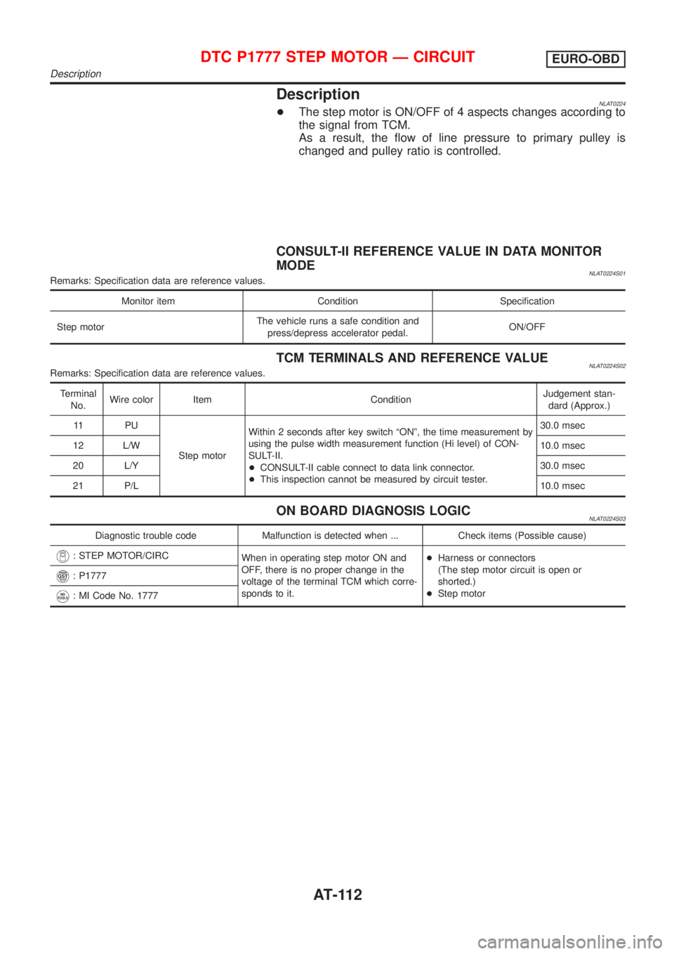
DescriptionNLAT0224+The step motor is ON/OFF of 4 aspects changes according to
the signal from TCM.
As a result, the flow of line pressure to primary pulley is
changed and pulley ratio is controlled.
CONSULT-II REFERENCE VALUE IN DATA MONITOR
MODE
NLAT0224S01Remarks: Specification data are reference values.
Monitor item Condition Specification
Step motorThe vehicle runs a safe condition and
press/depress accelerator pedal.ON/OFF
TCM TERMINALS AND REFERENCE VALUENLAT0224S02Remarks: Specification data are reference values.
Terminal
No.Wire color Item ConditionJudgement stan-
dard (Approx.)
11 P U
Step motorWithin 2 seconds after key switch ªONº, the time measurement by
using the pulse width measurement function (Hi level) of CON-
SULT-II.
+CONSULT-II cable connect to data link connector.
+This inspection cannot be measured by circuit tester.30.0 msec
12 L/W10.0 msec
20 L/Y30.0 msec
21 P/L10.0 msec
ON BOARD DIAGNOSIS LOGICNLAT0224S03
Diagnostic trouble code Malfunction is detected when ... Check items (Possible cause)
: STEP MOTOR/CIRC
When in operating step motor ON and
OFF, there is no proper change in the
voltage of the terminal TCM which corre-
sponds to it.+Harness or connectors
(The step motor circuit is open or
shorted.)
+Step motor
: P1777
: MI Code No. 1777
DTC P1777 STEP MOTOR Ð CIRCUITEURO-OBD
Description
AT-112
Page 147 of 3051
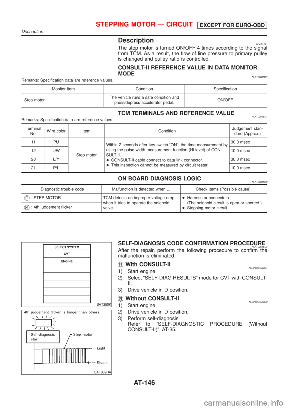
DescriptionNLAT0261The step motor is turned ON/OFF 4 times according to the signal
from TCM. As a result, the flow of line pressure to primary pulley
is changed and pulley ratio is controlled.
CONSULT-II REFERENCE VALUE IN DATA MONITOR
MODE
NLAT0261S05Remarks: Specification data are reference values.
Monitor item Condition Specification
Step motorThe vehicle runs a safe condition and
press/depress accelerator pedal.ON/OFF
TCM TERMINALS AND REFERENCE VALUENLAT0261S01Remarks: Specification data are reference values.
Terminal
No.Wire color Item ConditionJudgement stan-
dard (Approx.)
11 P U
Step motorWithin 2 seconds after key switch ªONº, the time measurement by
using the pulse width measurement function (Hi level) of CON-
SULT-II.
+CONSULT-II cable connect to data link connector.
+This inspection cannot be measured by circuit tester.30.0 msec
12 L/W10.0 msec
20 L/Y30.0 msec
21 P/L10.0 msec
ON BOARD DIAGNOSIS LOGICNLAT0261S02
Diagnostic trouble code Malfunction is detected when ... Check items (Possible cause)
: STEP MOTOR TCM detects an improper voltage drop
when it tries to operate the solenoid
valve.+Harness or connectors
(The solenoid circuit is open or shorted.)
+Stepping motor circuit
: 4th judgement flicker
SAT250K
SAT809HA
SELF-DIAGNOSIS CODE CONFIRMATION PROCEDURENLAT0261S03After the repair, perform the following procedure to confirm the
malfunction is eliminated.
With CONSULT-IINLAT0261S03011) Start engine.
2) Select ªSELF-DIAG RESULTSº mode for CVT with CONSULT-
II.
3) Drive vehicle in D position.
Without CONSULT-IINLAT0261S03021) Start engine.
2) Drive vehicle in D position.
3) Perform self-diagnosis.
Refer to ªSELF-DIAGNOSTIC PROCEDURE (Without
CONSULT-II)º, AT-35.
STEPPING MOTOR Ð CIRCUITEXCEPT FOR EURO-OBD
Description
AT-146
Page 165 of 3051
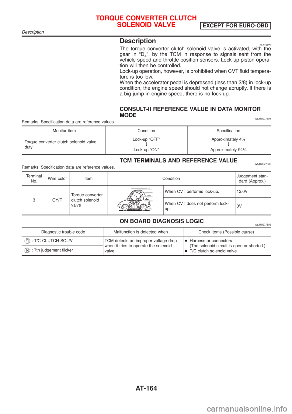
DescriptionNLAT0277The torque converter clutch solenoid valve is activated, with the
gear in ªD
4º, by the TCM in response to signals sent from the
vehicle speed and throttle position sensors. Lock-up piston opera-
tion will then be controlled.
Lock-up operation, however, is prohibited when CVT fluid tempera-
ture is too low.
When the accelerator pedal is depressed (less than 2/8) in lock-up
condition, the engine speed should not change abruptly. If there is
a big jump in engine speed, there is no lock-up.
CONSULT-II REFERENCE VALUE IN DATA MONITOR
MODE
NLAT0277S01Remarks: Specification data are reference values.
Monitor item Condition Specification
Torque converter clutch solenoid valve
dutyLock-up ªOFFº
¯
Lock-up ªONºApproximately 4%
¯
Approximately 94%
TCM TERMINALS AND REFERENCE VALUENLAT0277S02Remarks: Specification data are reference values.
Terminal
No.Wire color Item ConditionJudgement stan-
dard (Approx.)
3 GY/RTorque converter
clutch solenoid
valve
When CVT performs lock-up. 12.0V
When CVT does not perform lock-
up.0V
ON BOARD DIAGNOSIS LOGICNLAT0277S03
Diagnostic trouble code Malfunction is detected when ... Check items (Possible cause)
: T/C CLUTCH SOL/V TCM detects an improper voltage drop
when it tries to operate the solenoid
valve.+Harness or connectors
(The solenoid circuit is open or shorted.)
+T/C clutch solenoid valve
: 7th judgement flicker
TORQUE CONVERTER CLUTCH
SOLENOID VALVE
EXCEPT FOR EURO-OBD
Description
AT-164
Page 184 of 3051
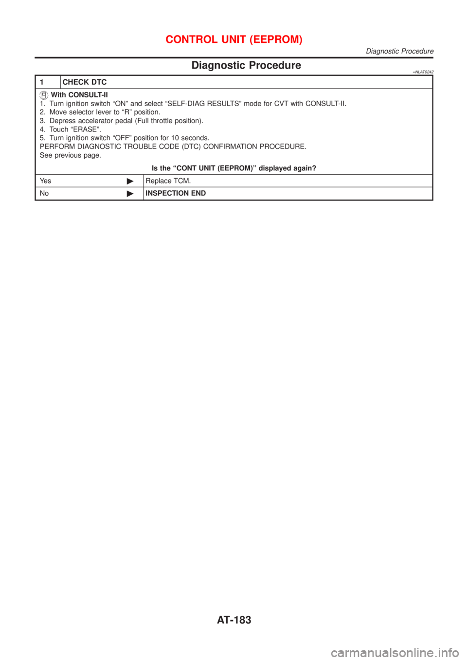
Diagnostic Procedure=NLAT0242
1 CHECK DTC
With CONSULT-II
1. Turn ignition switch ªONº and select ªSELF-DIAG RESULTSº mode for CVT with CONSULT-II.
2. Move selector lever to ªRº position.
3. Depress accelerator pedal (Full throttle position).
4. Touch ªERASEº.
5. Turn ignition switch ªOFFº position for 10 seconds.
PERFORM DIAGNOSTIC TROUBLE CODE (DTC) CONFIRMATION PROCEDURE.
See previous page.
Is the ªCONT UNIT (EEPROM)º displayed again?
Ye s©Replace TCM.
No©INSPECTION END
CONTROL UNIT (EEPROM)
Diagnostic Procedure
AT-183