2001 NISSAN ALMERA TINO injection
[x] Cancel search: injectionPage 7 of 3051

Precautions for Supplemental Restraint System
(SRS) ªAIR BAGº and ªSEAT BELT
PRE-TENSIONERº
NLAT0002The Supplemental Restraint System ªAIR BAGº and ªSEAT BELT PRE-TENSIONERº, used along with a seat
belt, help to reduce the risk or severity of injury to the driver and front passenger in a frontal collision. The
Supplemental Restraint System consists of air bag modules (located in the center of the steering wheel and
on the instrument panel on the passenger side), seat belt pre-tensioners, a diagnosis sensor unit, warning
lamp, wiring harness and spiral cable.
In addition to the supplemental air bag modules for a frontal collision, the supplemental side air bag used along
with the seat belt helps to reduce the risk or severity of injury to the driver and front passenger in a side col-
lision. The supplemental side air bag consists of air bag modules (located in the outer side of front seats),
satellite sensor, diagnosis sensor unit (one of components of supplemental air bags for a frontal collision),
wiring harness, warning lamp (one of components of supplemental air bags for a frontal collision). Information
necessary to service the system safely is included in theRS sectionof this Service Manual.
WARNING:
+To avoid rendering the SRS inoperative, which could increase the risk of personal injury or death
in the event of a collision which would result in air bag inflation, all maintenance must be performed
by an authorized NISSAN dealer.
+Improper maintenance, including incorrect removal and installation of the SRS, can lead to per-
sonal injury caused by unintentional activation of the system.
+Do not use electrical test equipment on any circuit related to the SRS unless instructed to in this
Service Manual. SRS wiring harnesses can be identified with yellow harness connector (and with
yellow harness protector or yellow insulation tape before the harness connectors).
Precautions for On Board Diagnostic (EURO-
OBD) System of CVT and Engine
NLAT0198The ECM has an on board diagnostic system. It will light up the malfunction indicator lamp (MI) to warn the
driver of a malfunction causing emission deterioration.
CAUTION:
+Be sure to turn the ignition switch ªOFFº and disconnect the negative battery terminal before any
repair or inspection work. The open/short circuit of related switches, sensors, solenoid valves, etc.
will cause the MI to light up.
+Be sure to connect and lock the connectors securely after work. A loose (unlocked) connector will
cause the MI to light up due to an open circuit. (Be sure the connector is free from water, grease,
dirt, bent terminals, etc.)
+Be sure to route and secure the harnesses properly after work. Interference of the harness with a
bracket, etc. may cause the MI to light up due to a short circuit.
+Be sure to connect rubber tubes properly after work. A misconnected or disconnected rubber tube
may cause the MI to light up due to a malfunction of the EGR system or fuel injection system, etc.
+Be sure to erase the unnecessary malfunction information (repairs completed) from the TCM and
ECM before returning the vehicle to the customer.
SEF289H
PrecautionsNLAT0003+Before connecting or disconnecting the TCM harness
connector, turn ignition switch OFF and disconnect nega-
tive battery terminal. Failure to do so may damage the
TCM. Because battery voltage is applied to TCM even if
ignition switch is turned off.
PRECAUTIONS
Precautions for Supplemental Restraint System (SRS) ªAIR BAGº and ªSEAT BELT PRE-TENSIONERº
AT-6
Page 20 of 3051
SAT015K
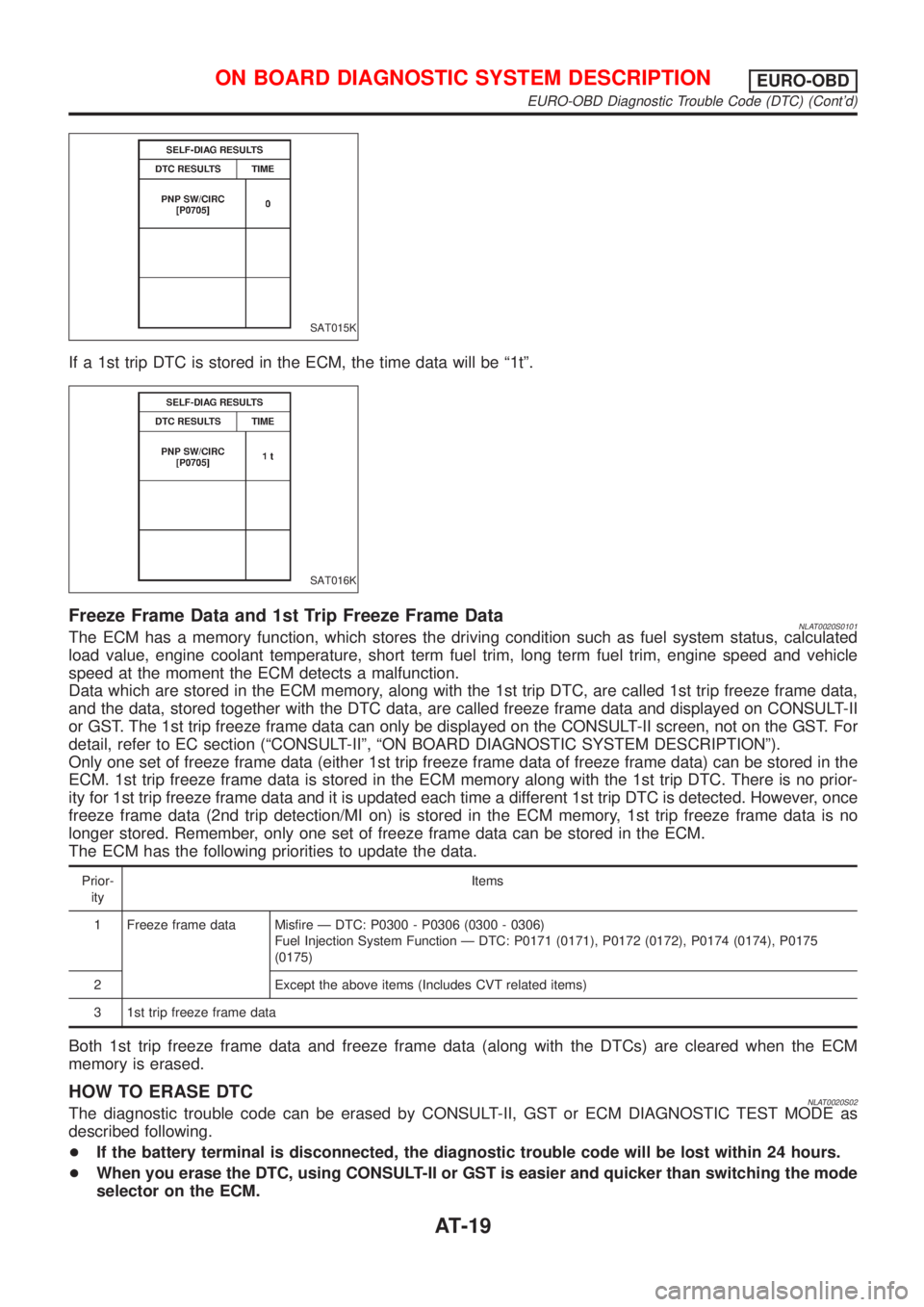
If a 1st trip DTC is stored in the ECM, the time data will be ª1tº.
SAT016K
Freeze Frame Data and 1st Trip Freeze Frame DataNLAT0020S0101The ECM has a memory function, which stores the driving condition such as fuel system status, calculated
load value, engine coolant temperature, short term fuel trim, long term fuel trim, engine speed and vehicle
speed at the moment the ECM detects a malfunction.
Data which are stored in the ECM memory, along with the 1st trip DTC, are called 1st trip freeze frame data,
and the data, stored together with the DTC data, are called freeze frame data and displayed on CONSULT-II
or GST. The 1st trip freeze frame data can only be displayed on the CONSULT-II screen, not on the GST. For
detail, refer to EC section (ªCONSULT-IIº, ªON BOARD DIAGNOSTIC SYSTEM DESCRIPTIONº).
Only one set of freeze frame data (either 1st trip freeze frame data of freeze frame data) can be stored in the
ECM. 1st trip freeze frame data is stored in the ECM memory along with the 1st trip DTC. There is no prior-
ity for 1st trip freeze frame data and it is updated each time a different 1st trip DTC is detected. However, once
freeze frame data (2nd trip detection/MI on) is stored in the ECM memory, 1st trip freeze frame data is no
longer stored. Remember, only one set of freeze frame data can be stored in the ECM.
The ECM has the following priorities to update the data.
Prior-
ityItems
1 Freeze frame data Misfire Ð DTC: P0300 - P0306 (0300 - 0306)
Fuel Injection System Function Ð DTC: P0171 (0171), P0172 (0172), P0174 (0174), P0175
(0175)
2 Except the above items (Includes CVT related items)
3 1st trip freeze frame data
Both 1st trip freeze frame data and freeze frame data (along with the DTCs) are cleared when the ECM
memory is erased.
HOW TO ERASE DTCNLAT0020S02The diagnostic trouble code can be erased by CONSULT-II, GST or ECM DIAGNOSTIC TEST MODE as
described following.
+If the battery terminal is disconnected, the diagnostic trouble code will be lost within 24 hours.
+When you erase the DTC, using CONSULT-II or GST is easier and quicker than switching the mode
selector on the ECM.
ON BOARD DIAGNOSTIC SYSTEM DESCRIPTIONEURO-OBD
EURO-OBD Diagnostic Trouble Code (DTC) (Cont'd)
AT-19
Page 426 of 3051
ENGINE CONTROL SYSTEM
SECTION
EC
CONTENTS
QG18DE
TROUBLE DIAGNOSIS - INDEX..................................16
Alphabetical & P No. Index for DTC .........................16
PRECAUTIONS.............................................................21
Precautions for Supplemental Restraint System
(SRS)²AIR BAG²and²SEAT BELT
PRE-TENSIONER²....................................................21
Precautions for On Board Diagnostic (OBD)
System of Engine ......................................................21
Engine Fuel & Emission Control System ..................22
Wiring Diagrams and Trouble Diagnosis ...................24
PREPARATION.............................................................25
Special Service Tools ................................................25
Commercial Service Tools .........................................25
ENGINE AND EMISSION CONTROL OVERALL
SYSTEM.........................................................................26
Engine Control Component Parts Location ...............26
Circuit Diagram ..........................................................30
System Diagram ........................................................32
Vacuum Hose Drawing ..............................................33
System Chart .............................................................34
ENGINE AND EMISSION BASIC CONTROL
SYSTEM DESCRIPTION...............................................35
Multiport Fuel Injection (MFI) System .......................35
Electronic Ignition (EI) System ..................................37
Air Conditioning Cut Control ......................................38
Fuel Cut Control (at no load & high engine
speed) ........................................................................39
Evaporative Emission System ...................................39
Positive Crankcase Ventilation ..................................42
BASIC SERVICE PROCEDURE...................................43
Fuel Pressure Release ..............................................43
Fuel Pressure Check .................................................43
Fuel Pressure Regulator Check ................................44
Injector .......................................................................44
How to Check Idle Speed and Ignition Timing ..........46
Preparation ................................................................47
Inspection Procedure .................................................49Idle Air Volume Learning ...........................................57
ON BOARD DIAGNOSTIC SYSTEM
DESCRIPTION...............................................................59
Introduction ................................................................59
Two Trip Detection Logic ...........................................59
Emission-related Diagnostic Information ...................60
NATS (Nissan Anti-theft System) ..............................72
Malfunction Indicator (MI) ..........................................73
OBD System Operation Chart (With Euro-OBD
Models Only)..............................................................77
CONSULT-II ...............................................................82
Generic Scan Tool (GST) ..........................................93
TROUBLE DIAGNOSIS - INTRODUCTION..................95
Introduction ................................................................95
Work Flow ..................................................................97
TROUBLE DIAGNOSIS - BASIC INSPECTION...........99
Basic Inspection.........................................................99
TROUBLE DIAGNOSIS - GENERAL
DESCRIPTION.............................................................122
DTC Inspection Priority Chart..................................122
Fail-safe Chart .........................................................123
Symptom Matrix Chart .............................................124
CONSULT-II Reference Value in Data Monitor
Mode ........................................................................128
Major Sensor Reference Graph in Data Monitor
Mode ........................................................................130
ECM Terminals and Reference Value .....................133
TROUBLE DIAGNOSIS - SPECIFICATION VALUE..141
Description ...............................................................141
Testing Condition .....................................................141
Inspection Procedure ...............................................141
Diagnostic Procedure ..............................................142
TROUBLE DIAGNOSIS FOR INTERMITTENT
INCIDENT.....................................................................145
Description ...............................................................145
Diagnostic Procedure ..............................................145
TROUBLE DIAGNOSIS FOR POWER SUPPLY........146
Main Power Supply and Ground Circuit ..................146
Page 428 of 3051
On Board Diagnosis Logic.......................................221
DTC Confirmation Procedure ..................................222
Wiring Diagram ........................................................223
Diagnostic Procedure ..............................................225
Component Inspection .............................................226
DTC P0137 HEATED OXYGEN SENSOR 2
(REAR) (MIN. VOLTAGE MONITORING)...................227
Component Description ...........................................227
CONSULT-II Reference Value in Data Monitor
Mode ........................................................................227
ECM Terminals and Reference Value .....................227
On Board Diagnosis Logic.......................................227
DTC Confirmation Procedure ..................................228
Overall Function Check ...........................................229
Wiring Diagram ........................................................230
Diagnostic Procedure ..............................................232
Component Inspection .............................................235
DTC P0138 HEATED OXYGEN SENSOR 2
(REAR) (MAX. VOLTAGE MONITORING).................237
Component Description ...........................................237
CONSULT-II Reference Value in Data Monitor
Mode ........................................................................237
ECM Terminals and Reference Value .....................237
On Board Diagnosis Logic.......................................237
DTC Confirmation Procedure ..................................238
Overall Function Check ...........................................239
Wiring Diagram ........................................................240
Diagnostic Procedure ..............................................242
Component Inspection .............................................244
DTC P0139 HEATED OXYGEN SENSOR 2
(REAR) (RESPONSE MONITORING).........................246
Component Description ...........................................246
CONSULT-II Reference Value in Data Monitor
Mode ........................................................................246
ECM Terminals and Reference Value .....................246
On Board Diagnosis Logic.......................................246
DTC Confirmation Procedure ..................................247
Overall Function Check ...........................................248
Wiring Diagram ........................................................249
Diagnostic Procedure ..............................................251
Component Inspection .............................................254
DTC P0140 HEATED OXYGEN SENSOR 2
(REAR) (HIGH VOLTAGE)..........................................256
Component Description ...........................................256
CONSULT-II Reference Value in Data Monitor
Mode ........................................................................256
ECM Terminals and Reference Value .....................256
On Board Diagnosis Logic.......................................256
DTC Confirmation Procedure ..................................257
Overall Function Check ...........................................257
Wiring Diagram ........................................................258
Diagnostic Procedure ..............................................260Component Inspection .............................................261
DTC P0141 HEATED OXYGEN SENSOR 2
HEATER (REAR).........................................................263
Description ...............................................................263
CONSULT-II Reference Value in Data Monitor
Mode ........................................................................263
ECM Terminals and Reference Value .....................263
On Board Diagnosis Logic.......................................264
DTC Confirmation Procedure ..................................264
Wiring Diagram ........................................................265
Diagnostic Procedure ..............................................267
Component Inspection .............................................268
DTC P0171 FUEL INJECTION SYSTEM
FUNCTION (LEAN SIDE)............................................269
On Board Diagnosis Logic.......................................269
DTC Confirmation Procedure ..................................269
Wiring Diagram ........................................................271
Diagnostic Procedure ..............................................273
DTC P0172 FUEL INJECTION SYSTEM
FUNCTION (RICH SIDE).............................................277
On Board Diagnosis Logic.......................................277
DTC Confirmation Procedure ..................................277
Wiring Diagram ........................................................279
Diagnostic Procedure ..............................................281
DTC P0300 - P0304 NO.4-1CYLINDER
MISFIRE, MULTIPLE CYLINDER MISFIRE...............285
On Board Diagnosis Logic.......................................285
DTC Confirmation Procedure ..................................285
Diagnostic Procedure ..............................................286
DTC P0325 KNOCK SENSOR (KS)...........................291
Component Description ...........................................291
ECM Terminals and Reference Value .....................291
On Board Diagnosis Logic.......................................291
DTC Confirmation Procedure ..................................291
Wiring Diagram ........................................................292
Diagnostic Procedure ..............................................293
Component Inspection .............................................294
DTC P0335 CRANKSHAFT POSITION SENSOR
(POS)............................................................................295
Component Description ...........................................295
ECM Terminals and Reference Value .....................295
On Board Diagnosis Logic.......................................296
DTC Confirmation Procedure ..................................296
Wiring Diagram ........................................................297
Diagnostic Procedure ..............................................299
Component Inspection .............................................301
DTC P0340 CAMSHAFT POSITION SENSOR
(CMPS) (PHASE).........................................................302
Component Description ...........................................302
ECM Terminals and Reference Value .....................302
On Board Diagnosis Logic.......................................303
DTC Confirmation Procedure ..................................303
CONTENTS(Cont'd)
EC-3
Page 432 of 3051
Crankshaft Position Sensor (POS) ..........................549
Camshaft Position Sensor (PHASE) .......................549
SR20DE
TROUBLE DIAGNOSIS - INDEX................................550
Alphabetical & P No. Index for DTC .......................550
PRECAUTIONS...........................................................555
Precautions for Supplemental Restraint System
(SRS)²AIR BAG²and²SEAT BELT
PRE-TENSIONER²..................................................555
Precautions for On Board Diagnostic (OBD)
System of Engine and CVT .....................................555
Engine Fuel & Emission Control System ................556
Wiring Diagrams and Trouble Diagnosis .................558
PREPARATION...........................................................559
Special Service Tools ..............................................559
Commercial Service Tools .......................................559
ENGINE AND EMISSION CONTROL OVERALL
SYSTEM.......................................................................560
Engine Control Component Parts Location .............560
Circuit Diagram ........................................................564
System Diagram ......................................................566
Vacuum Hose Drawing ............................................567
System Chart ...........................................................568
ENGINE AND EMISSION BASIC CONTROL
SYSTEM DESCRIPTION.............................................569
Multiport Fuel Injection (MFI) System .....................569
Electronic Ignition (EI) System ................................571
Air Conditioning Cut Control ....................................572
Fuel Cut Control (at no load & high engine
speed) ......................................................................573
Evaporative Emission System .................................573
Positive Crankcase Ventilation ................................576
BASIC SERVICE PROCEDURE.................................577
Fuel Pressure Release ............................................577
Fuel Pressure Check ...............................................577
Fuel Pressure Regulator Check ..............................578
Injector .....................................................................578
Idle Air Volume Learning .........................................581
ON BOARD DIAGNOSTIC SYSTEM
DESCRIPTION.............................................................583
Introduction ..............................................................583
Two Trip Detection Logic .........................................583
Emission-related Diagnostic Information .................584
NATS (Nissan Anti-theft System) ............................597
Malfunction Indicator (MI) ........................................598
OBD System Operation Chart (With Euro-OBD
Models Only)............................................................602
CONSULT-II .............................................................607
Generic Scan Tool (GST) ........................................617
TROUBLE DIAGNOSIS - INTRODUCTION................619
Introduction ..............................................................619Work Flow ................................................................621
TROUBLE DIAGNOSIS - BASIC INSPECTION.........623
Basic Inspection (Models with Throttle Opener) .....623
Basic Inspection (Models without Throttle
Opener) ....................................................................638
TROUBLE DIAGNOSIS - GENERAL
DESCRIPTION.............................................................646
DTC Inspection Priority Chart..................................646
Fail-safe Chart .........................................................647
Symptom Matrix Chart .............................................648
CONSULT-II Reference Value in Data Monitor
Mode ........................................................................652
Major Sensor Reference Graph in Data Monitor
Mode ........................................................................654
ECM Terminals and Reference Value .....................657
TROUBLE DIAGNOSIS - SPECIFICATION VALUE..666
Description ...............................................................666
Testing Condition .....................................................666
Inspection Procedure ...............................................666
Diagnostic Procedure ..............................................667
TROUBLE DIAGNOSIS FOR INTERMITTENT
INCIDENT.....................................................................670
Description ...............................................................670
Diagnostic Procedure ..............................................670
TROUBLE DIAGNOSIS FOR POWER SUPPLY........671
Main Power Supply and Ground Circuit ..................671
DTC P0100 MASS AIR FLOW SENSOR (MAFS)......679
Component Description ...........................................679
CONSULT-II Reference Value in Data Monitor
Mode ........................................................................679
ECM Terminals and Reference Value .....................679
On Board Diagnosis Logic.......................................679
Fail-safe Mode .........................................................680
DTC Confirmation Procedure ..................................680
Wiring Diagram ........................................................682
Diagnostic Procedure ..............................................684
Component Inspection .............................................686
DTC P0110 INTAKE AIR TEMPERATURE
SENSOR......................................................................687
Component Description ...........................................687
On Board Diagnosis Logic.......................................688
DTC Confirmation Procedure ..................................688
Wiring Diagram ........................................................689
Diagnostic Procedure ..............................................691
Component Inspection .............................................693
DTC P0115 ENGINE COOLANT TEMPERATURE
SENSOR (ECTS) (CIRCUIT).......................................694
Component Description ...........................................694
CONSULT-II Reference Value in Data Monitor
Mode ........................................................................694
On Board Diagnosis Logic.......................................694
Fail-safe Mode .........................................................695
CONTENTS(Cont'd)
EC-7
Page 434 of 3051
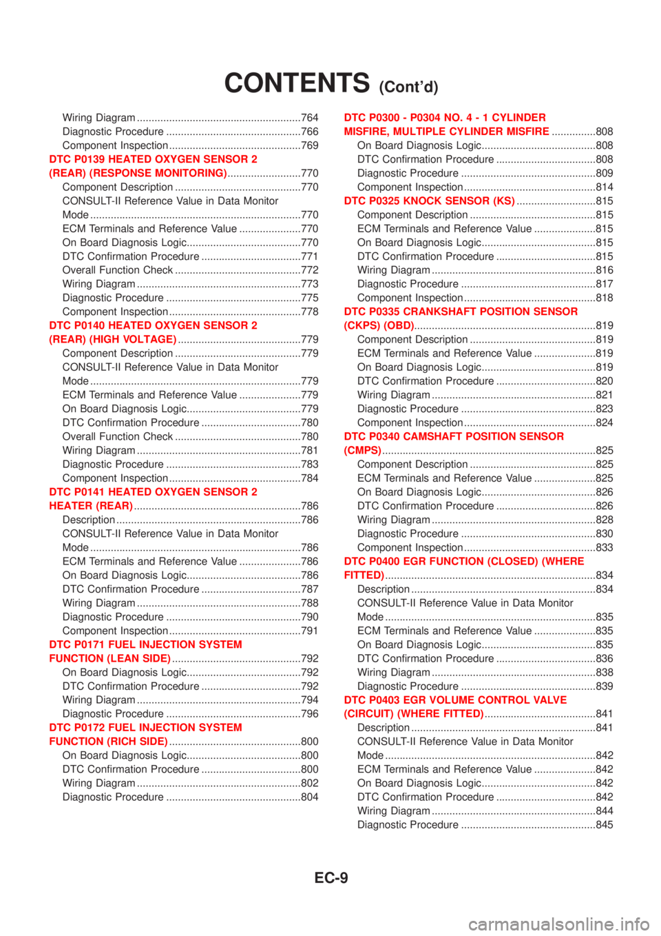
Wiring Diagram ........................................................764
Diagnostic Procedure ..............................................766
Component Inspection .............................................769
DTC P0139 HEATED OXYGEN SENSOR 2
(REAR) (RESPONSE MONITORING).........................770
Component Description ...........................................770
CONSULT-II Reference Value in Data Monitor
Mode ........................................................................770
ECM Terminals and Reference Value .....................770
On Board Diagnosis Logic.......................................770
DTC Confirmation Procedure ..................................771
Overall Function Check ...........................................772
Wiring Diagram ........................................................773
Diagnostic Procedure ..............................................775
Component Inspection .............................................778
DTC P0140 HEATED OXYGEN SENSOR 2
(REAR) (HIGH VOLTAGE)..........................................779
Component Description ...........................................779
CONSULT-II Reference Value in Data Monitor
Mode ........................................................................779
ECM Terminals and Reference Value .....................779
On Board Diagnosis Logic.......................................779
DTC Confirmation Procedure ..................................780
Overall Function Check ...........................................780
Wiring Diagram ........................................................781
Diagnostic Procedure ..............................................783
Component Inspection .............................................784
DTC P0141 HEATED OXYGEN SENSOR 2
HEATER (REAR).........................................................786
Description ...............................................................786
CONSULT-II Reference Value in Data Monitor
Mode ........................................................................786
ECM Terminals and Reference Value .....................786
On Board Diagnosis Logic.......................................786
DTC Confirmation Procedure ..................................787
Wiring Diagram ........................................................788
Diagnostic Procedure ..............................................790
Component Inspection .............................................791
DTC P0171 FUEL INJECTION SYSTEM
FUNCTION (LEAN SIDE)............................................792
On Board Diagnosis Logic.......................................792
DTC Confirmation Procedure ..................................792
Wiring Diagram ........................................................794
Diagnostic Procedure ..............................................796
DTC P0172 FUEL INJECTION SYSTEM
FUNCTION (RICH SIDE).............................................800
On Board Diagnosis Logic.......................................800
DTC Confirmation Procedure ..................................800
Wiring Diagram ........................................................802
Diagnostic Procedure ..............................................804DTC P0300 - P0304 NO.4-1CYLINDER
MISFIRE, MULTIPLE CYLINDER MISFIRE...............808
On Board Diagnosis Logic.......................................808
DTC Confirmation Procedure ..................................808
Diagnostic Procedure ..............................................809
Component Inspection .............................................814
DTC P0325 KNOCK SENSOR (KS)...........................815
Component Description ...........................................815
ECM Terminals and Reference Value .....................815
On Board Diagnosis Logic.......................................815
DTC Confirmation Procedure ..................................815
Wiring Diagram ........................................................816
Diagnostic Procedure ..............................................817
Component Inspection .............................................818
DTC P0335 CRANKSHAFT POSITION SENSOR
(CKPS) (OBD)..............................................................819
Component Description ...........................................819
ECM Terminals and Reference Value .....................819
On Board Diagnosis Logic.......................................819
DTC Confirmation Procedure ..................................820
Wiring Diagram ........................................................821
Diagnostic Procedure ..............................................823
Component Inspection .............................................824
DTC P0340 CAMSHAFT POSITION SENSOR
(CMPS).........................................................................825
Component Description ...........................................825
ECM Terminals and Reference Value .....................825
On Board Diagnosis Logic.......................................826
DTC Confirmation Procedure ..................................826
Wiring Diagram ........................................................828
Diagnostic Procedure ..............................................830
Component Inspection .............................................833
DTC P0400 EGR FUNCTION (CLOSED) (WHERE
FITTED)........................................................................834
Description ...............................................................834
CONSULT-II Reference Value in Data Monitor
Mode ........................................................................835
ECM Terminals and Reference Value .....................835
On Board Diagnosis Logic.......................................835
DTC Confirmation Procedure ..................................836
Wiring Diagram ........................................................838
Diagnostic Procedure ..............................................839
DTC P0403 EGR VOLUME CONTROL VALVE
(CIRCUIT) (WHERE FITTED)......................................841
Description ...............................................................841
CONSULT-II Reference Value in Data Monitor
Mode ........................................................................842
ECM Terminals and Reference Value .....................842
On Board Diagnosis Logic.......................................842
DTC Confirmation Procedure ..................................842
Wiring Diagram ........................................................844
Diagnostic Procedure ..............................................845
CONTENTS(Cont'd)
EC-9
Page 437 of 3051
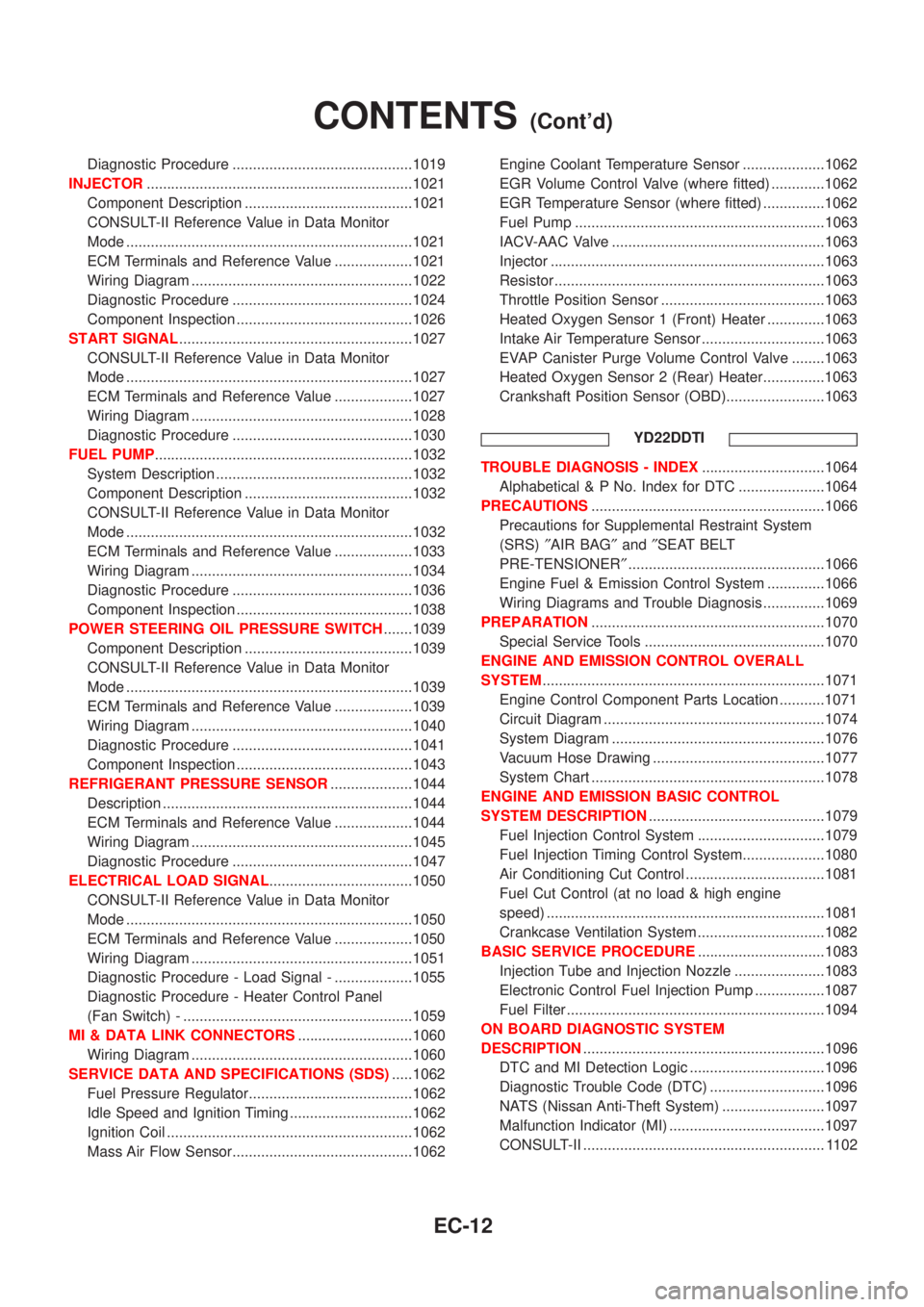
Diagnostic Procedure ............................................1019
INJECTOR.................................................................1021
Component Description .........................................1021
CONSULT-II Reference Value in Data Monitor
Mode ......................................................................1021
ECM Terminals and Reference Value ...................1021
Wiring Diagram ......................................................1022
Diagnostic Procedure ............................................1024
Component Inspection ...........................................1026
START SIGNAL.........................................................1027
CONSULT-II Reference Value in Data Monitor
Mode ......................................................................1027
ECM Terminals and Reference Value ...................1027
Wiring Diagram ......................................................1028
Diagnostic Procedure ............................................1030
FUEL PUMP...............................................................1032
System Description ................................................1032
Component Description .........................................1032
CONSULT-II Reference Value in Data Monitor
Mode ......................................................................1032
ECM Terminals and Reference Value ...................1033
Wiring Diagram ......................................................1034
Diagnostic Procedure ............................................1036
Component Inspection ...........................................1038
POWER STEERING OIL PRESSURE SWITCH.......1039
Component Description .........................................1039
CONSULT-II Reference Value in Data Monitor
Mode ......................................................................1039
ECM Terminals and Reference Value ...................1039
Wiring Diagram ......................................................1040
Diagnostic Procedure ............................................1041
Component Inspection ...........................................1043
REFRIGERANT PRESSURE SENSOR....................1044
Description .............................................................1044
ECM Terminals and Reference Value ...................1044
Wiring Diagram ......................................................1045
Diagnostic Procedure ............................................1047
ELECTRICAL LOAD SIGNAL...................................1050
CONSULT-II Reference Value in Data Monitor
Mode ......................................................................1050
ECM Terminals and Reference Value ...................1050
Wiring Diagram ......................................................1051
Diagnostic Procedure - Load Signal - ...................1055
Diagnostic Procedure - Heater Control Panel
(Fan Switch) - ........................................................1059
MI & DATA LINK CONNECTORS............................1060
Wiring Diagram ......................................................1060
SERVICE DATA AND SPECIFICATIONS (SDS).....1062
Fuel Pressure Regulator........................................1062
Idle Speed and Ignition Timing ..............................1062
Ignition Coil ............................................................1062
Mass Air Flow Sensor............................................1062Engine Coolant Temperature Sensor ....................1062
EGR Volume Control Valve (where fitted) .............1062
EGR Temperature Sensor (where fitted) ...............1062
Fuel Pump .............................................................1063
IACV-AAC Valve ....................................................1063
Injector ...................................................................1063
Resistor ..................................................................1063
Throttle Position Sensor ........................................1063
Heated Oxygen Sensor 1 (Front) Heater ..............1063
Intake Air Temperature Sensor ..............................1063
EVAP Canister Purge Volume Control Valve ........1063
Heated Oxygen Sensor 2 (Rear) Heater...............1063
Crankshaft Position Sensor (OBD)........................1063
YD22DDTI
TROUBLE DIAGNOSIS - INDEX..............................1064
Alphabetical & P No. Index for DTC .....................1064
PRECAUTIONS.........................................................1066
Precautions for Supplemental Restraint System
(SRS)²AIR BAG²and²SEAT BELT
PRE-TENSIONER²................................................1066
Engine Fuel & Emission Control System ..............1066
Wiring Diagrams and Trouble Diagnosis ...............1069
PREPARATION.........................................................1070
Special Service Tools ............................................1070
ENGINE AND EMISSION CONTROL OVERALL
SYSTEM.....................................................................1071
Engine Control Component Parts Location ...........1071
Circuit Diagram ......................................................1074
System Diagram ....................................................1076
Vacuum Hose Drawing ..........................................1077
System Chart .........................................................1078
ENGINE AND EMISSION BASIC CONTROL
SYSTEM DESCRIPTION...........................................1079
Fuel Injection Control System ...............................1079
Fuel Injection Timing Control System....................1080
Air Conditioning Cut Control ..................................1081
Fuel Cut Control (at no load & high engine
speed) ....................................................................1081
Crankcase Ventilation System ...............................1082
BASIC SERVICE PROCEDURE...............................1083
Injection Tube and Injection Nozzle ......................1083
Electronic Control Fuel Injection Pump .................1087
Fuel Filter ...............................................................1094
ON BOARD DIAGNOSTIC SYSTEM
DESCRIPTION...........................................................1096
DTC and MI Detection Logic .................................1096
Diagnostic Trouble Code (DTC) ............................1096
NATS (Nissan Anti-Theft System) .........................1097
Malfunction Indicator (MI) ......................................1097
CONSULT-II ........................................................... 1102
CONTENTS(Cont'd)
EC-12
Page 440 of 3051
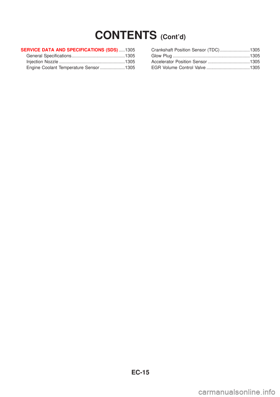
SERVICE DATA AND SPECIFICATIONS (SDS).....1305
General Specifications ...........................................1305
Injection Nozzle .....................................................1305
Engine Coolant Temperature Sensor ....................1305Crankshaft Position Sensor (TDC) ........................1305
Glow Plug ..............................................................1305
Accelerator Position Sensor ..................................1305
EGR Volume Control Valve ...................................1305
CONTENTS(Cont'd)
EC-15