Page 207 of 3051

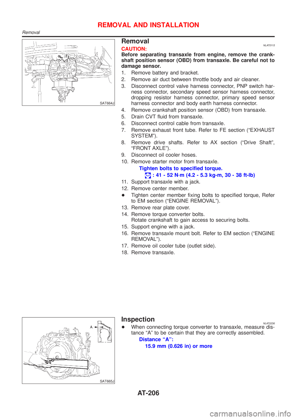
SAT664J
RemovalNLAT0115CAUTION:
Before separating transaxle from engine, remove the crank-
shaft position sensor (OBD) from transaxle. Be careful not to
damage sensor.
1. Remove battery and bracket.
2. Remove air duct between throttle body and air cleaner.
3. Disconnect control valve harness connector, PNP switch har-
ness connector, secondary speed sensor harness connector,
dropping resistor harness connector, primary speed sensor
harness connector and body earth harness connector.
4. Remove crankshaft position sensor (OBD) from transaxle.
5. Drain CVT fluid from transaxle.
6. Disconnect control cable from transaxle.
7. Remove exhaust front tube. Refer to FE section (ªEXHAUST
SYSTEMº).
8. Remove drive shafts. Refer to AX section (ªDrive Shaftº,
ªFRONT AXLEº).
9. Disconnect oil cooler hoses.
10. Remove starter motor from transaxle.
Tighten bolts to specified torque.
: 41 - 52 N´m (4.2 - 5.3 kg-m, 30 - 38 ft-lb)
11. Support transaxle with a jack.
12. Remove center member.
+Tighten center member fixing bolts to specified torque, Refer
to EM section (ªENGINE REMOVALº).
13. Remove rear plate cover.
14. Remove torque converter bolts.
Rotate crankshaft to gain access to securing bolts.
15. Support engine with a jack.
16. Remove transaxle mount bolt. Refer to EM section (ªENGINE
REMOVALº).
17. Remove oil cooler tube (outlet side).
18. Remove transaxle.
SAT665J
InspectionNLAT0236+When connecting torque converter to transaxle, measure dis-
tance ªAº to be certain that they are correctly assembled.
Distance ªAº:
15.9 mm (0.626 in) or more
REMOVAL AND INSTALLATION
Removal
AT-206
Page 247 of 3051
SBR686C
InstallationNLBR0013CAUTION:
+Refill with new brake fluid“DOT 4”.
+Never reuse drained brake fluid.
1. Tighten all flare nuts and connecting bolts.
Specification:
Flare nut
15-18N·m (1.5 - 1.8 kg-m, 11 - 13 ft-lb)
Connecting bolt
17-20N·m (1.7 - 2.0 kg-m, 12 - 14 ft-lb)
2. Refill until new brake fluid comes out of each air bleeder valve.
3. Bleed air. Refer to“Bleeding Brake System”, BR-8, and‘‘Air
Bleeding Procedure’’, CL-10.
BRAKE HYDRAULIC LINE
Installation
BR-10
Page 254 of 3051
InstallationNLBR0026CAUTION:
+Be careful not to deform or bend brake pipes, during
booster installation.
+Replace clevis pin if damaged.
+Refill with new brake fluid“DOT 4”.
+Never reuse drained brake fluid.
+Take care not to damage brake booster mounting bolt
thread during installation. Due to the acute angle of
installation, the threads can be damaged with the dash
panel.
SBR237EA
1. Before fitting booster, temporarily adjust clevis to dimension
shown.
2. Fit booster, then secure mounting nuts (brake pedal bracket to
master cylinder) lightly.
3. Connect brake pedal and booster input rod with clevis pin.
4. Secure mounting nuts.
Specification:
13-16N·m (1.3 - 1.6 kg-m,9-12ft-lb)
5. Install master cylinder. Refer to“Installation”in“MASTER
CYLINDER”, BR-15.
6. Bleed air. Refer to“Bleeding Brake System”, BR-8 and“Air
Bleeding Procedure”, CL-10.
BRAKE BOOSTER
Installation
BR-17
Page 264 of 3051
SBR574
AssemblyNLBR00341. Insert piston seal into groove on cylinder body.
2. With piston boot fitted to piston, insert piston boot into groove
on cylinder body and install piston.
3. Properly secure piston boot.
SBR980B
InstallationNLBR0035CAUTION:
+Refill with new brake fluid“DOT 4”.
+Never reuse drained brake fluid.
1. Install brake hose to caliper securely.
2. Install all parts and secure all bolts.
3. Bleed air. Refer to“Bleeding Brake System”, BR-8.
FRONT DISC BRAKE
Assembly
BR-27
Page 272 of 3051
NBR375
InstallationNLBR0043CAUTION:
+Refill with new brake fluid“DOT 4”.
+Never reuse drained brake fluid.
1. Install caliper assembly.
+As shown in the figure, align the piston’s concave to the pad’s
convex, then install the cylinder body to the torque member.
2. Install brake hose to caliper securely.
3. Install all parts and secure all bolts.
4. Bleed air. Refer to“Bleeding Brake System”, BR-8 and“Air
Bleeding Procedure”, CL-10.
REAR DISC BRAKE (CAM & STRUT TYPE)
Installation
BR-35
Page 275 of 3051

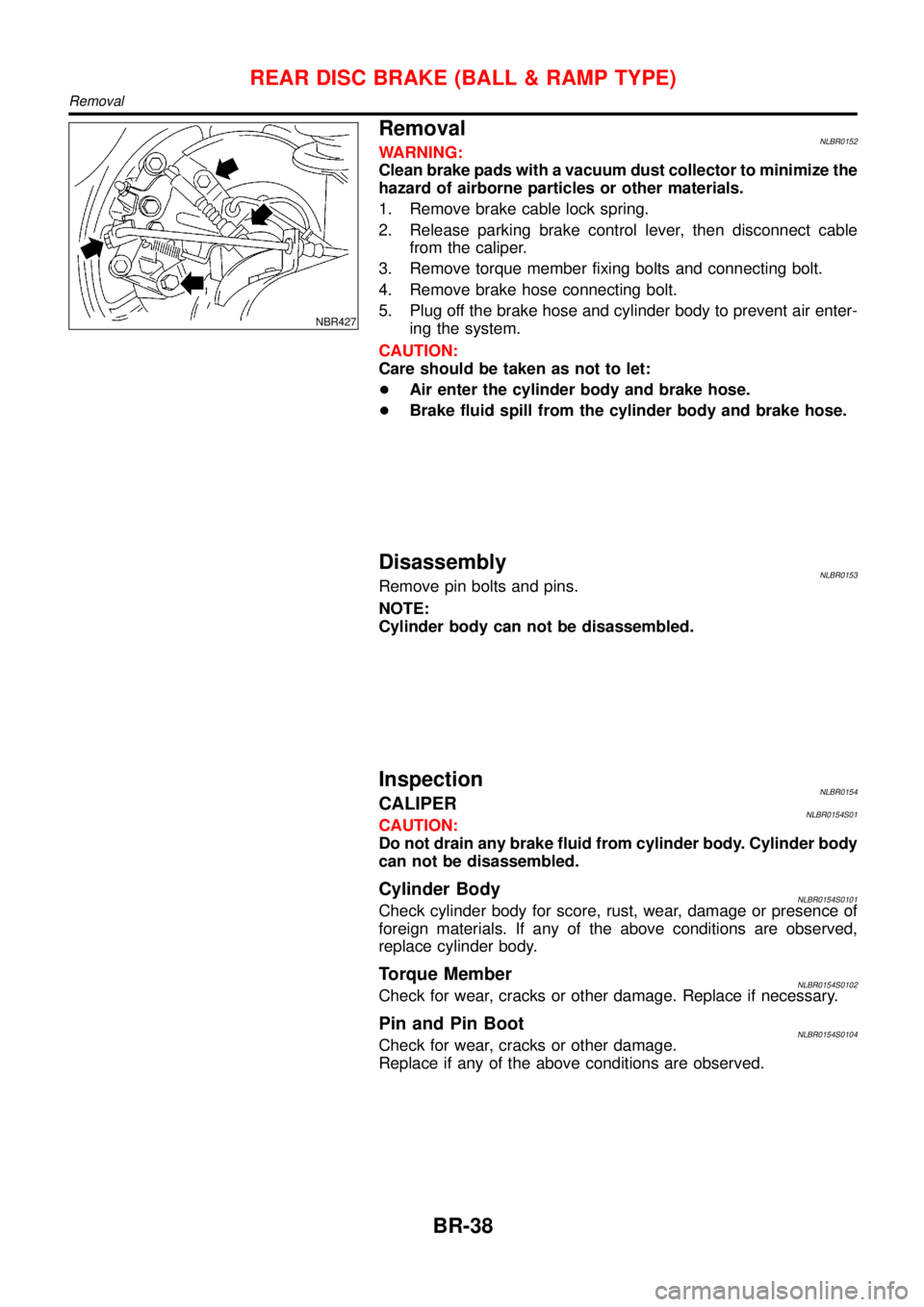
NBR427
RemovalNLBR0152WARNING:
Clean brake pads with a vacuum dust collector to minimize the
hazard of airborne particles or other materials.
1. Remove brake cable lock spring.
2. Release parking brake control lever, then disconnect cable
from the caliper.
3. Remove torque member fixing bolts and connecting bolt.
4. Remove brake hose connecting bolt.
5. Plug off the brake hose and cylinder body to prevent air enter-
ing the system.
CAUTION:
Care should be taken as not to let:
+Air enter the cylinder body and brake hose.
+Brake fluid spill from the cylinder body and brake hose.
DisassemblyNLBR0153Remove pin bolts and pins.
NOTE:
Cylinder body can not be disassembled.
InspectionNLBR0154CALIPERNLBR0154S01CAUTION:
Do not drain any brake fluid from cylinder body. Cylinder body
can not be disassembled.
Cylinder BodyNLBR0154S0101Check cylinder body for score, rust, wear, damage or presence of
foreign materials. If any of the above conditions are observed,
replace cylinder body.
Torque MemberNLBR0154S0102Check for wear, cracks or other damage. Replace if necessary.
Pin and Pin BootNLBR0154S0104Check for wear, cracks or other damage.
Replace if any of the above conditions are observed.
REAR DISC BRAKE (BALL & RAMP TYPE)
Removal
BR-38
Page 276 of 3051

SBR219C
ROTORNLBR0154S02Rubbing SurfaceNLBR0154S0201Check rotor for roughness, cracks or chips.
RunoutNLBR0154S02021. Secure rotor to wheel hub with two nuts (M12 x 1.25).
2. Check runout using a dial indicator.
Make sure that axial end play is within the specifications
before measuring. Refer to AX section (“REAR WHEEL
BEARING”,“On-vehicle Service”).
3. Change relative positions of rotor and wheel hub so that runout
is minimized.
Maximum runout:
0.07 mm (0.0028 in)
ThicknessNLBR0154S0203Rotor repair limit:
Standard thickness
10 mm (0.39 in)
Minimum thickness
9 mm (0.35 in)
Thickness variation (At least 8 portions)
Maximum 0.02 mm (0.0008 in)
NBR374
NBR375
InstallationNLBR0156CAUTION:
+Refill with new brake fluid“DOT 4”.
+Never reuse drained brake fluid.
+Do not drain (factory) filled brake fluid from (new) caliper
assemblies.
1. Install caliper assembly.
+As shown in the figure, align the piston’s concave to the pad’s
convex, then install the cylinder body to the torque member.
2. Remove the plug from the cylinder body and brake hose.
CAUTION:
Care should be taken as not to let:
+Air enter the cylinder body and brake hose.
+Brake fluid spill from the cylinder body and brake hose.
3. Install brake hose to caliper securely.
4. Install all parts and secure all bolts.
5. Bleed air. Refer to“Bleeding Brake System”, BR-8 and“Air
Bleeding Procedure”, CL-10.
REAR DISC BRAKE (BALL & RAMP TYPE)
Inspection (Cont’d)
BR-39
Page 328 of 3051
ABS Actuator and Electric UnitNLBR0111S10
SBR630E
REMOVALNLBR0111S10011. Disconnect battery cable.
2. Drain brake fluid.
3. Remove mounting bracket fixing bolts and nuts.
4. Disconnect connector, brake pipes and remove fixing nuts.
INSTALLATIONNLBR0111S1002CAUTION:
After installation, refill brake fluid. Then bleed air.
1. Connect brake pipes temporarily.
2. Tighten fixing bolts and nuts.
3. Tighten brake pipes.
4. Connect connector and battery cable.
REMOVAL AND INSTALLATIONABS
ABS Actuator and Electric Unit
BR-91