Page 2807 of 3051

NLMT0008
SMT928D
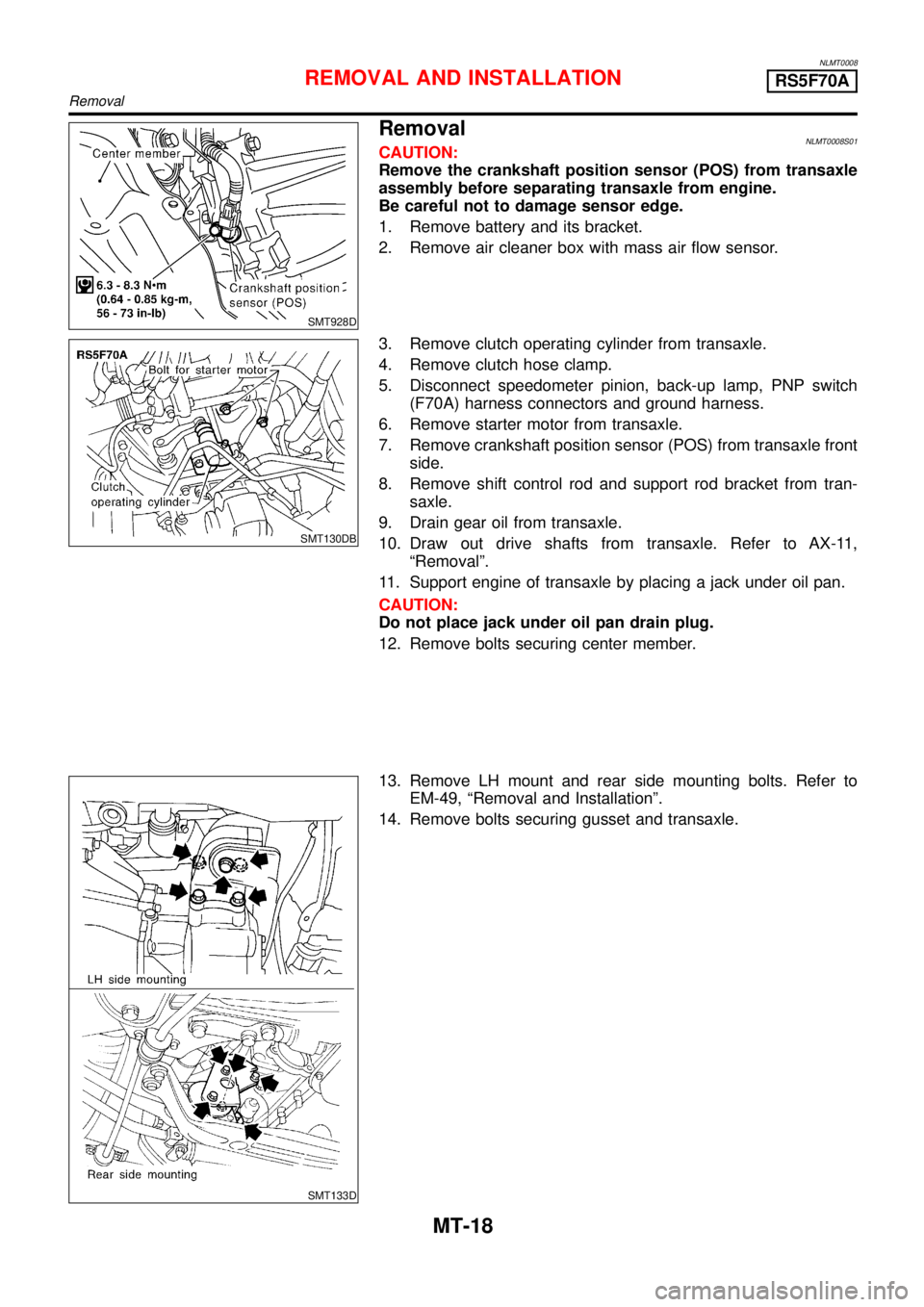
RemovalNLMT0008S01CAUTION:
Remove the crankshaft position sensor (POS) from transaxle
assembly before separating transaxle from engine.
Be careful not to damage sensor edge.
1. Remove battery and its bracket.
2. Remove air cleaner box with mass air flow sensor.
SMT130DB
3. Remove clutch operating cylinder from transaxle.
4. Remove clutch hose clamp.
5. Disconnect speedometer pinion, back-up lamp, PNP switch
(F70A) harness connectors and ground harness.
6. Remove starter motor from transaxle.
7. Remove crankshaft position sensor (POS) from transaxle front
side.
8. Remove shift control rod and support rod bracket from tran-
saxle.
9. Drain gear oil from transaxle.
10. Draw out drive shafts from transaxle. Refer to AX-11,
“Removal”.
11. Support engine of transaxle by placing a jack under oil pan.
CAUTION:
Do not place jack under oil pan drain plug.
12. Remove bolts securing center member.
SMT133D
13. Remove LH mount and rear side mounting bolts. Refer to
EM-49,“Removal and Installation”.
14. Remove bolts securing gusset and transaxle.
REMOVAL AND INSTALLATIONRS5F70A
Removal
MT-18
Page 2809 of 3051

NLMT0090
SMT928D
RemovalNLMT0090S01CAUTION:
Remove the crankshaft position sensor (POS) from transaxle
assembly before separating transaxle from engine.
Be careful not to damage sensor edge.
1. Remove battery and its bracket.
2. Remove fuse box from battery bracket.
3. Remove air cleaner box with mass air flow sensor.
4. Remove air breather hose and vacuum pump hose.
5. Remove fuel filter bracket bolts.
SMT650CB
6. Remove terminal and connector from starter motor.
7. Remove starter motor from transaxle.
8. Remove clutch hose clamp.
9. Remove clutch operating cylinder from transaxle.
10. Disconnect speedometer pinion, PNP switch harness connec-
tors and ground harness.
11. Remove crankshaft position sensor (POS) from transaxle front
side.
12. Remove front exhaust tube.
SMT929D
13. Remove shift control rod and support rod bracket from tran-
saxle.
14. Drain gear oil from transaxle.
15. Draw out drive shafts from transaxle. Refer to AX-11,
“Removal”.
16. Support engine and transaxle by placing a jack under the tran-
saxle.
17. Remove bolts securing center member.
SMT950D
18. Take out engine mounting bracket and transaxle installation
bolts. Refer to EM-49,“Removal and Installation”.
19. Remove bolts securing transaxle under side.
20. Temporarily tighten center member.
21. Lower the lift.
REMOVAL AND INSTALLATIONRS5F50A
Removal
MT-20
Page 2817 of 3051
NLMT0055
SMT648D
Transaxle CaseNLMT0055S011. Remove reverse switch, PNP switch, drain plug, and filler plug
from transaxle case.
SMT644D
2. Remove snap rings from reverse idler shaft.
3. Remove side cover and rear cover from case.
4. Remove O-ring and mainshaft bearing adjusting shim.
SMT645D
5. Remove reverse idler gear shaft.
a. Attach bolt (M6) to thread of reverse idler gear shaft end.
b. Pull out the attached bolt, and remove reverse idler gear shaft
from case.
6. Remove reverse idler gear, thrust washer (front, rear), and
bearing from case.
SMT646D
7. Remove snap ring of mainshaft bearing from case.
SMT647D
8. Remove check plugs, springs, and check balls from case.
DISASSEMBLYRS5F70A
Transaxle Case
MT-28
Page 2848 of 3051

SMT649D
11. Install transaxle case onto clutch housing, and tighten mount-
ing bolts with specified torque.
Tightening torque:
Refer to MT-24.
SMT648D
12. Apply Three Bond TB1215, Loctite Part No. 51813 or equiva-
lent to threads of reverse switch, PNP switch, and drain plug,
and install them. (Fill the case with oil before installation of filler
plug.)
13. Install speedometer pinion assembly.
CAUTION:
Do not reuse O-ring.
SMT749D
14. Install check springs and check balls. Apply sealant to the
thread on the check plug, and install it.
SMT746D
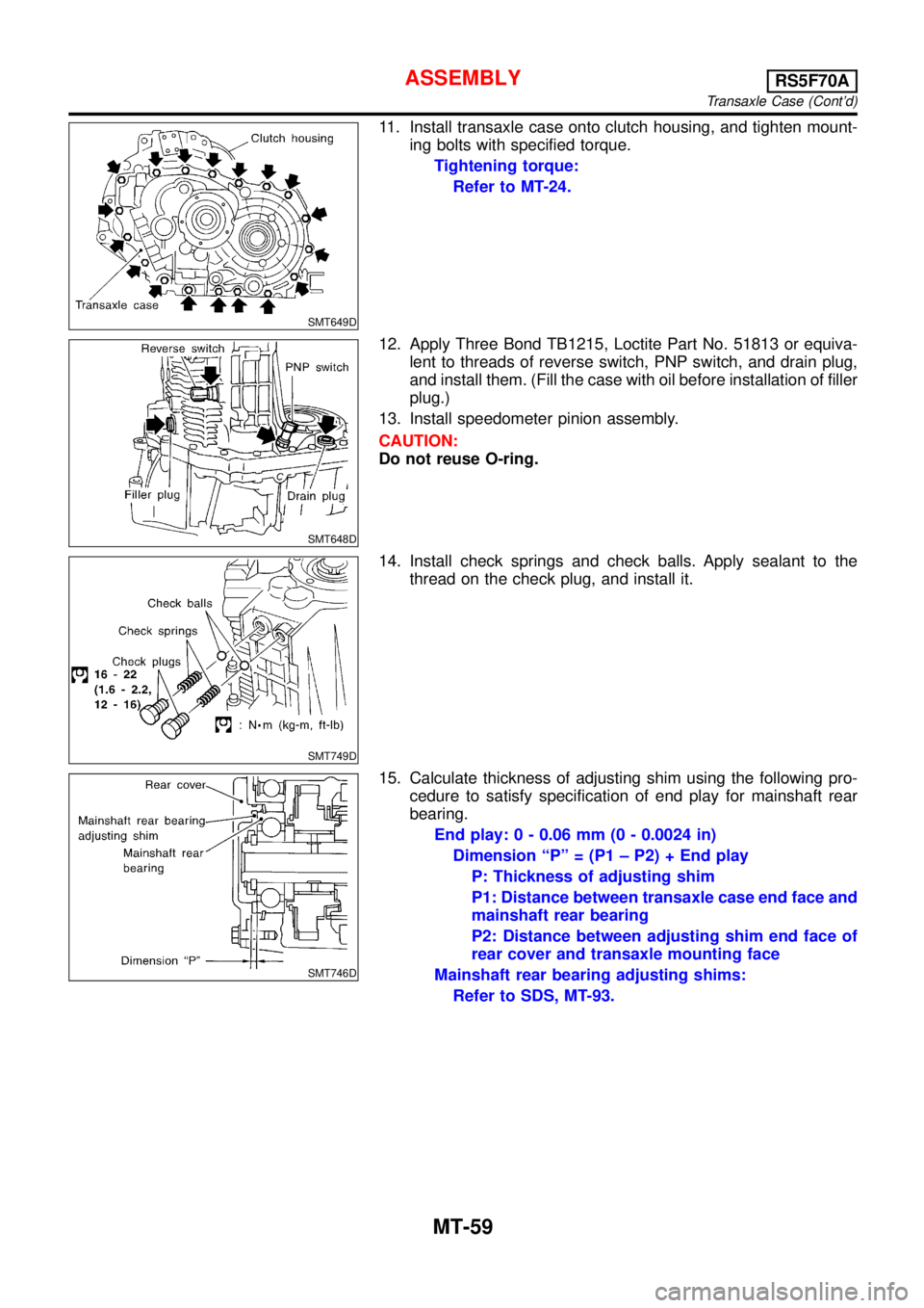
15. Calculate thickness of adjusting shim using the following pro-
cedure to satisfy specification of end play for mainshaft rear
bearing.
End play: 0 - 0.06 mm (0 - 0.0024 in)
Dimension“P”= (P1–P2) + End play
P: Thickness of adjusting shim
P1: Distance between transaxle case end face and
mainshaft rear bearing
P2: Distance between adjusting shim end face of
rear cover and transaxle mounting face
Mainshaft rear bearing adjusting shims:
Refer to SDS, MT-93.
ASSEMBLYRS5F70A
Transaxle Case (Cont’d)
MT-59
Page 3046 of 3051

SRA695A
SSU038
REMOVALNLSU0031S01CAUTION:
+Before removing the rear suspension assembly, discon-
nect the ABS wheel sensor from the assembly. Failure to
do so may result in damage to the sensor wires and the
sensor becoming inoperative.
+Remove suspension assembly.
1. Disconnect brake hydraulic lines and parking brake cable at
toggle lever. (Models with drum brakes.)
+Drain brake fluid before disconnecting brake lines.
2. Disconnect parking brake cable from caliper and remove brake
caliper and rotor. (Models with disc brakes.)
Suspend caliper assembly with wire so as not to stretch
brake hose.
Be careful not to depress brake pedal, or piston will pop
out.
Make sure brake hose is not twisted.
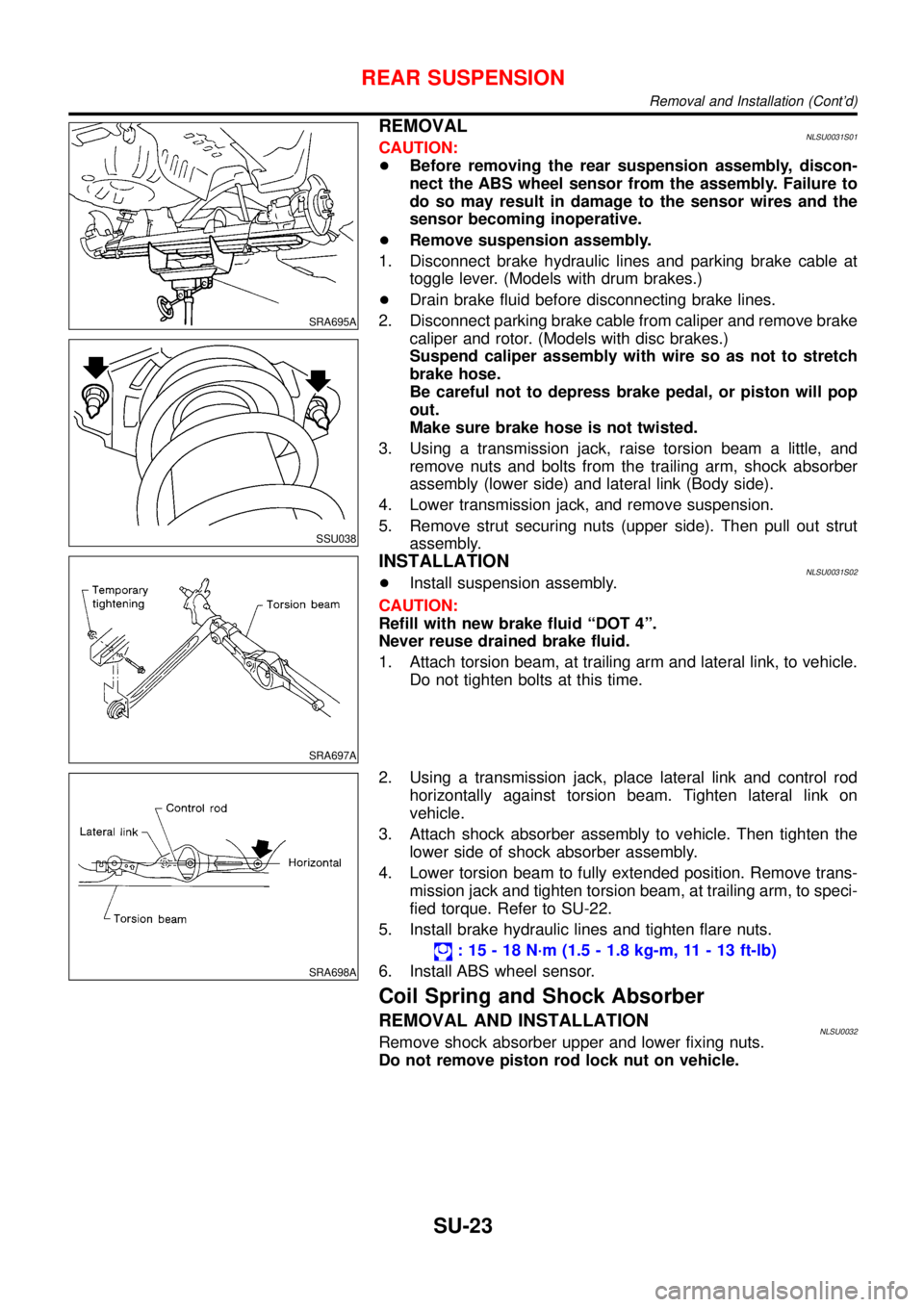
3. Using a transmission jack, raise torsion beam a little, and
remove nuts and bolts from the trailing arm, shock absorber
assembly (lower side) and lateral link (Body side).
4. Lower transmission jack, and remove suspension.
5. Remove strut securing nuts (upper side). Then pull out strut
assembly.
SRA697A
INSTALLATIONNLSU0031S02+Install suspension assembly.
CAUTION:
Refill with new brake fluid“DOT 4”.
Never reuse drained brake fluid.
1. Attach torsion beam, at trailing arm and lateral link, to vehicle.
Do not tighten bolts at this time.
SRA698A
2. Using a transmission jack, place lateral link and control rod
horizontally against torsion beam. Tighten lateral link on
vehicle.
3. Attach shock absorber assembly to vehicle. Then tighten the
lower side of shock absorber assembly.
4. Lower torsion beam to fully extended position. Remove trans-
mission jack and tighten torsion beam, at trailing arm, to speci-
fied torque. Refer to SU-22.
5. Install brake hydraulic lines and tighten flare nuts.
:15-18N·m (1.5 - 1.8 kg-m, 11 - 13 ft-lb)
6. Install ABS wheel sensor.
Coil Spring and Shock Absorber
REMOVAL AND INSTALLATIONNLSU0032Remove shock absorber upper and lower fixing nuts.
Do not remove piston rod lock nut on vehicle.
REAR SUSPENSION
Removal and Installation (Cont’d)
SU-23