Page 2361 of 3051

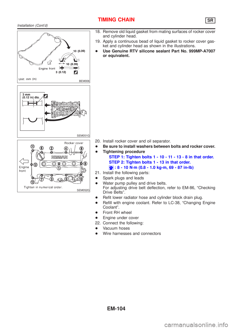
BEM006
SEM051G
18. Remove old liquid gasket from mating surfaces of rocker cover
and cylinder head.
19. Apply a continuous bead of liquid gasket to rocker cover gas-
ket and cylinder head as shown in the illustrations.
+Use Genuine RTV silicone sealant Part No. 999MP-A7007
or equivalent.
SEM052G
20. Install rocker cover and oil separator.
+Be sure to install washers between bolts and rocker cover.
+Tightening procedure
STEP 1: Tighten bolts1-10-11-13-8inthat order.
STEP 2: Tighten bolts1-13inthat order.
:8-10N´m(0.8 - 1.0 kg-m, 69 - 87 in-lb)
21. Install the following parts:
+Spark plugs and leads
+Water pump pulley and drive belts.
For adjusting drive belt deflection, refer to EM-86, ªChecking
Drive Beltsº.
+Refit lower radiator hose and cylinder block drain plug.
+Refill with engine coolant. Refer to LC-38, ªChanging Engine
Coolantº.
+Front RH wheel
+Engine under cover
22. Connect the following:
+Vacuum hoses
+Wire harnesses and connectors
TIMING CHAINSR
Installation (Cont'd)
EM-104
Page 2366 of 3051
RemovalNLEM01311. Release fuel pressure.
Refer to EC-578, ªFuel Pressure Releaseº.
2. Remove engine under covers.
3. Remove front RH wheel and engine side cover.
4. Drain coolant by removing cylinder block drain plug and radia-
tor drain cock. Refer to LC-38, ªChanging Engine Coolantº.
5. Remove radiator.
6. Remove air duct to intake manifold.
7. Disconnect the following parts:
+Vacuum hoses
+Fuel hoses
+Wires
+Harness
+Connectors
+Front exhaust tube
8. Remove all spark plugs.
SEM029G
9. Remove rocker cover bolts in numerical order.
10. Remove rocker cover.
SEM030G
11. Remove intake manifold supports.
SEM065G
12. Remove water pipe assembly.
CYLINDER HEADSR
Removal
EM-109
Page 2448 of 3051
Removal and InstallationNLEM0101
JEM264G
PREPARATIVE WORKNLEM0101S01Remove the following parts.
+Under cover
+Engine coolant (drain)
Refer to LC-59, ªChanging Engine Coolantº.
+Radiator upper hose
+Cooling fan
Refer to LC-58, ªRadiatorº.
+Radiator mount bracket
+Water inlet pipe
+Exhaust front tube (disconnect)
Refer to FE-23, ªRemoval and Installationº, ªEXHAUST SYS-
TEMº.
THREE WAY CATALYSTNLEM0101S02RemovalNLEM0101S0201CAUTION:
Do not disassemble.
InstallationNLEM0101S0202Install two locking pins into both sides of the catalytic converter. Be
careful not to confuse locking pins with insulator mounting bolts.
Catalytic converter locking pin:
Flange bolt (black)
Insulator mounting bolt:
Washer bolt (silver or yellow)
CATALYSTYD
Removal and Installation
EM-191
Page 2458 of 3051

CAUTION:
+When installing camshafts, chain tensioners, oil seals, or
other sliding parts, lubricate contacting surfaces with new
engine oil.
+Apply new engine oil to threads and seat surfaces when
installing cylinder head, camshaft sprocket, crankshaft
pulley, and camshaft bracket.
+Attach tags to valve lifters so as not to mix them up.
RemovalNLEM0063PREPARATIVE WORKNLEM0063S011. Drain engine coolant. Refer to LC-59, ªChanging Engine Cool-
antº.
2. Remove exhaust manifold. Refer to EM-193, ªRemovalº.
3. Remove intake manifold. Refer to EM-189, ªRemovalº.
+Apply paint to camshaft sprockets for alignment during
installation.
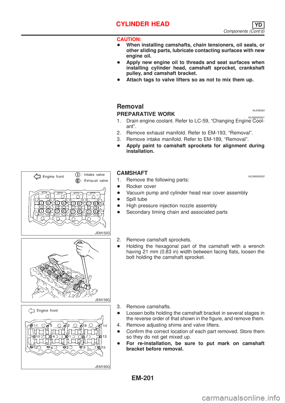
JEM152G
CAMSHAFTNLEM0063S021. Remove the following parts:
+Rocker cover
+Vacuum pump and cylinder head rear cover assembly
+Spill tube
+High pressure injection nozzle assembly
+Secondary timing chain and associated parts
JEM159G
2. Remove camshaft sprockets.
+Holding the hexagonal part of the camshaft with a wrench
having 21 mm (0.83 in) width between facing flats, loosen the
bolt holding the camshaft sprocket.
JEM160G
3. Remove camshafts.
+Loosen bolts holding the camshaft bracket in several stages in
the reverse order of that shown in the figure, and remove them.
4. Remove adjusting shims and valve lifters.
+Confirm the correct location of each part removed. Store them
so they do not get mixed up.
+For re-installation, be sure to put mark on camshaft
bracket before removal.
CYLINDER HEADYD
Components (Cont'd)
EM-201
Page 2476 of 3051

crankshaft position sensor (TDC sensor) from the assem-
bly.
+Always pay extra attention not to damage edge of crank-
shaft position sensor (TDC sensor) or ring gear teeth.
REMOVALNLEM0069S011. Remove engine undercover, and hood for hoisting.
2. Drain coolant from both cylinder block and radiator. Refer to
LC-59, ªChanging Engine Coolantº.
3. Remove the following parts:
+Battery
+RH and LH front wheels
+RH and LH splash covers (combined with undercover)
+Auxiliary belts
+Alternator
+Alternator brackets
+Radiator and cooling fan
+Engine cover
+Air ducts and air cleaner case
LH side of engine room:
4. Disconnect all harnesses and grounds that are connected to
components on vehicle.
5. Disconnect vacuum hose on vacuum pump side.
6. Disconnect fuel feed and fuel return hoses on engine side.
+Immediately put blind plugs into the openings to prevent
fuel from flowing out.
7. Disconnect heater hose. Plug opening of hose to prevent cool-
ant from flowing out.
RH side of engine room:
8. Remove air conditioner compressor from brackets and move
it toward vehicle side. Secure compressor on vehicle side with
rope.
Vehicle underside:
9. Remove exhaust front tube.
10. Disconnect two hoses from power steering pump and plug to
stop fluid.
11. Remove M/T control rod and support rod.
12. Remove ABS wheel sensor, and temporarily hang brake cali-
per with rope on vehicle side.
13. Remove RH and LH drive shafts.
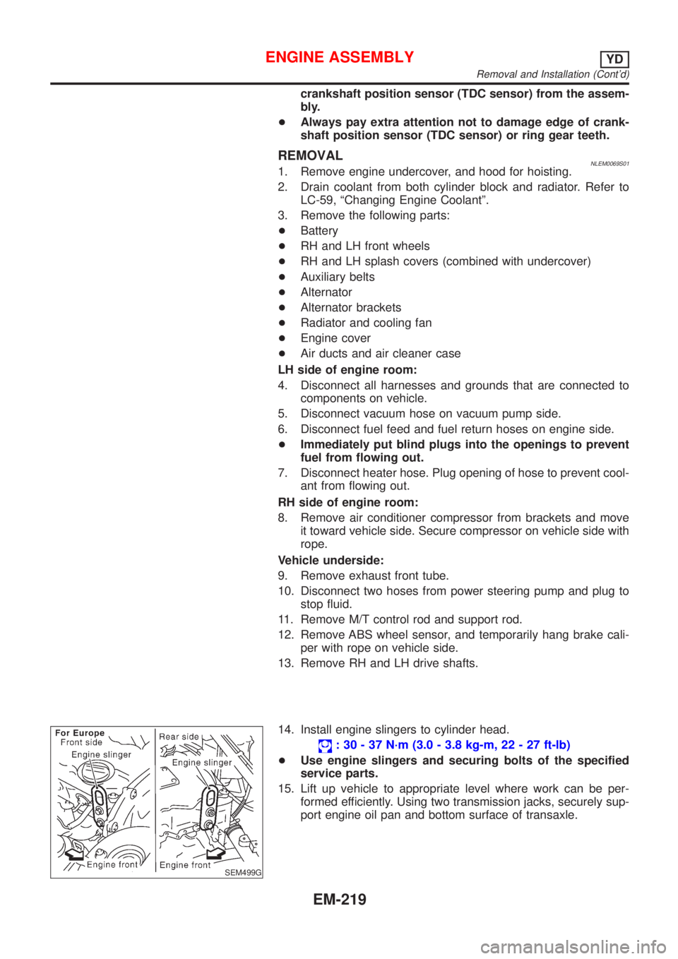
SEM499G
14. Install engine slingers to cylinder head.
: 30 - 37 N´m (3.0 - 3.8 kg-m, 22 - 27 ft-lb)
+Use engine slingers and securing bolts of the specified
service parts.
15. Lift up vehicle to appropriate level where work can be per-
formed efficiently. Using two transmission jacks, securely sup-
port engine oil pan and bottom surface of transaxle.
ENGINE ASSEMBLYYD
Removal and Installation (Cont'd)
EM-219
Page 2717 of 3051
Water Pump
REMOVAL AND INSTALLATIONNLLC0018
SEM858F
SEM859F
CAUTION:
+When removing water pump assembly, be careful not to
get coolant on drive belt.
+Water pump cannot be disassembled and should be
replaced as a unit.
+After installing water pump, and check for leaks using
radiator cap tester.
1. Drain engine coolant.
Refer to LC-19, ªChanging Engine Coolantº.
2. Remove drive belts and idler pulley.
3. Loosen water pump pulley bolts.
4. Remove water pump pulley.
5. Remove front right wheel.
6. Remove front right undercover and front right fender protector.
7. Remove water pump bolts.
8. Remove water pump.
9. Reinstall parts in reverse order of removal.
SEM860F
INSPECTIONNLLC0019+Check body assembly and vane for rust or corrosion.
+Check for rough operation due to excessive end play.
ENGINE COOLING SYSTEMQG
Water Pump
LC-14
Page 2753 of 3051
Oil CoolerNLLC0077
NLC096
REMOVAL AND INSTALLATIONNLLC0077S011. Draining the coolant
Refer to LC-59, ªChanging Engine Coolantº.
2. Remove the exhaust front tube.
SLC359B
3. Reinstall all removed parts in the reverse order of removal.
+Confirm that no foreign objects are adhering to the installation
planes of the oil cooler or block.
+Tighten the connecting bolt after aligning the stopper on the
cylinder block side with protrusion of the oil cooler.
ENGINE LUBRICATION SYSTEMYD
Oil Cooler
LC-50
Page 2759 of 3051
JLC294B
REMOVALNLLC00561. Remove the undercover, splash cover (right), and accessory
belt.
2. Drain engine coolant. Refer to LC-59, ªChanging Engine Cool-
antº.
3. Support the bottom of the oil pan with a floor jack etc., and
remove the right engine mount bracket (front side of the
engine).
4. Remove the water pump pulley.
+Loosen the pulley bolts after fixing the pulley using a screw-
driver etc.
5. Remove engine mount brackets.
6. Remove the water pump.
INSPECTIONNLLC0057+Check for rust and contamination adhering to the water pump
and vane.
+Turn the pump shaft by hand, and check that the pump turns
smoothly without looseness.
INSTALLATIONNLLC0058+Install the parts in the reverse order of removal.
+Install the water pump pulley with the front mark (painted white,
used to prevent errors during assembly) facing the front of the
engine. Refer to the figure above.
ENGINE COOLING SYSTEMYD
Water Pump (Cont'd)
LC-56