2001 NISSAN ALMERA TINO Esp off
[x] Cancel search: Esp offPage 95 of 3051
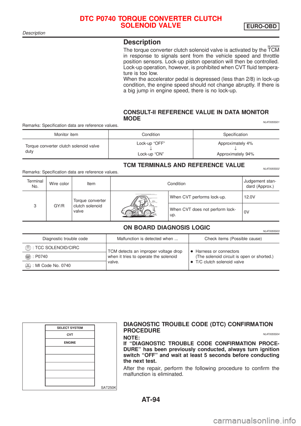
DescriptionNLAT0055The torque converter clutch solenoid valve is activated by the TCM
in response to signals sent from the vehicle speed and throttle
position sensors. Lock-up piston operation will then be controlled.
Lock-up operation, however, is prohibited when CVT fluid tempera-
ture is too low.
When the accelerator pedal is depressed (less than 2/8) in lock-up
condition, the engine speed should not change abruptly. If there is
a big jump in engine speed, there is no lock-up.
CONSULT-II REFERENCE VALUE IN DATA MONITOR
MODE
NLAT0055S01Remarks: Specification data are reference values.
Monitor item Condition Specification
Torque converter clutch solenoid valve
dutyLock-up ªOFFº
¯
Lock-up ªONºApproximately 4%
¯
Approximately 94%
TCM TERMINALS AND REFERENCE VALUENLAT0055S02Remarks: Specification data are reference values.
Terminal
No.Wire color Item ConditionJudgement stan-
dard (Approx.)
3 GY/RTorque converter
clutch solenoid
valve
When CVT performs lock-up. 12.0V
When CVT does not perform lock-
up.0V
ON BOARD DIAGNOSIS LOGICNLAT0055S03
Diagnostic trouble code Malfunction is detected when ... Check items (Possible cause)
: TCC SOLENOID/CIRC
TCM detects an improper voltage drop
when it tries to operate the solenoid
valve.+Harness or connectors
(The solenoid circuit is open or shorted.)
+T/C clutch solenoid valve
: P0740
: MI Code No. 0740
SAT250K
DIAGNOSTIC TROUBLE CODE (DTC) CONFIRMATION
PROCEDURE
NLAT0055S04NOTE:
If ªDIAGNOSTIC TROUBLE CODE CONFIRMATION PROCE-
DUREº has been previously conducted, always turn ignition
switch ªOFFº and wait at least 5 seconds before conducting
the next test.
After the repair, perform the following procedure to confirm the
malfunction is eliminated.
DTC P0740 TORQUE CONVERTER CLUTCH
SOLENOID VALVE
EURO-OBD
Description
AT-94
Page 100 of 3051
DescriptionNLAT0061The line pressure solenoid valve regulates the oil pump discharge
pressure to suit the driving condition in response to a signal sent
from the TCM.
The line pressure duty cycle value is not consistent when the
closed throttle position switch is ªONº. To confirm the line
pressure duty cycle at low pressure, the accelerator (throttle)
should be open until the closed throttle position switch is
ªOFFº.
CONSULT-II REFERENCE VALUE IN DATA MONITOR
MODE
NLAT0061S01Remarks: Specification data are reference values.
Monitor item Condition Specification
Line pressure solenoid valve dutySmall throttle opening
(Low line pressure)
¯
Large throttle opening
(High line pressure)Approximately 4%
¯
Approximately 94%
NOTE:
The line pressure duty cycle value is not consistent when the closed throttle position switch is ªONº. To confirm the line pressure duty
cycle at low pressure, the accelerator (throttle) should be open until the closed throttle position switch is ªOFFº.
TCM TERMINALS AND REFERENCE VALUENLAT0061S02Remarks: Specification data are reference values.
Terminal
No.Wire color Item ConditionJudgement stan-
dard (Approx.)
1 R/WLine pressure
solenoid valve
When releasing accelerator pedal
after warming up engine.2.8V
When depressing accelerator pedal
fully after warming up engine.1.4V
2 P/BLine pressure
solenoid valve
(with dropping
resistor)When releasing accelerator pedal
after warming up engine.11.0V
When depressing accelerator pedal
fully after warming up engine.4.0V
ON BOARD DIAGNOSIS LOGICNLAT0061S03
Diagnostic trouble code Malfunction is detected when ... Check items (Possible cause)
: L/PRESS SOL/CIRC
TCM detects an improper voltage drop
when it tries to operate the solenoid
valve.+Harness or connectors
(The solenoid circuit is open or shorted.)
+Line pressure solenoid valve
: P0745
: MI Code No. 0745
DTC P0745 LINE PRESSURE SOLENOID VALVEEURO-OBD
Description
AT-99
Page 105 of 3051
SAT233K
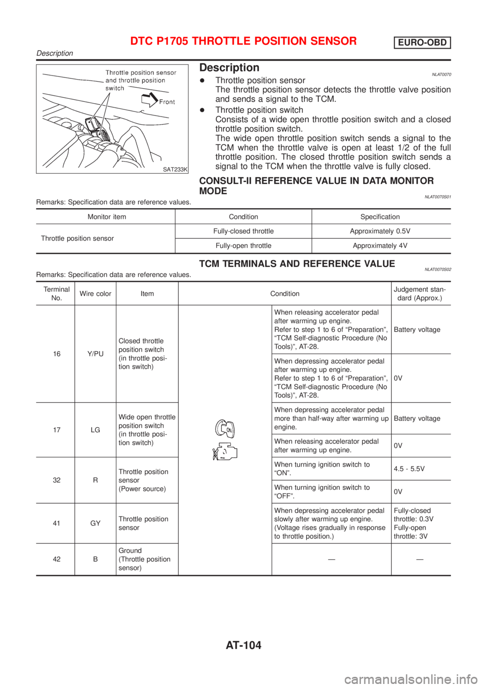
DescriptionNLAT0070+Throttle position sensor
The throttle position sensor detects the throttle valve position
and sends a signal to the TCM.
+Throttle position switch
Consists of a wide open throttle position switch and a closed
throttle position switch.
The wide open throttle position switch sends a signal to the
TCM when the throttle valve is open at least 1/2 of the full
throttle position. The closed throttle position switch sends a
signal to the TCM when the throttle valve is fully closed.
CONSULT-II REFERENCE VALUE IN DATA MONITOR
MODE
NLAT0070S01Remarks: Specification data are reference values.
Monitor item Condition Specification
Throttle position sensorFully-closed throttle Approximately 0.5V
Fully-open throttle Approximately 4V
TCM TERMINALS AND REFERENCE VALUENLAT0070S02Remarks: Specification data are reference values.
Terminal
No.Wire color Item ConditionJudgement stan-
dard (Approx.)
16 Y/PUClosed throttle
position switch
(in throttle posi-
tion switch)
When releasing accelerator pedal
after warming up engine.
Refer to step 1 to 6 of ªPreparationº,
ªTCM Self-diagnostic Procedure (No
Tools)º, AT-28.Battery voltage
When depressing accelerator pedal
after warming up engine.
Refer to step 1 to 6 of ªPreparationº,
ªTCM Self-diagnostic Procedure (No
Tools)º, AT-28.0V
17 LGWide open throttle
position switch
(in throttle posi-
tion switch)When depressing accelerator pedal
more than half-way after warming up
engine.Battery voltage
When releasing accelerator pedal
after warming up engine.0V
32 RThrottle position
sensor
(Power source)When turning ignition switch to
ªONº.4.5 - 5.5V
When turning ignition switch to
ªOFFº.0V
41 GYThrottle position
sensorWhen depressing accelerator pedal
slowly after warming up engine.
(Voltage rises gradually in response
to throttle position.)Fully-closed
throttle: 0.3V
Fully-open
throttle: 3V
42 BGround
(Throttle position
sensor)ÐÐ
DTC P1705 THROTTLE POSITION SENSOREURO-OBD
Description
AT-104
Page 138 of 3051
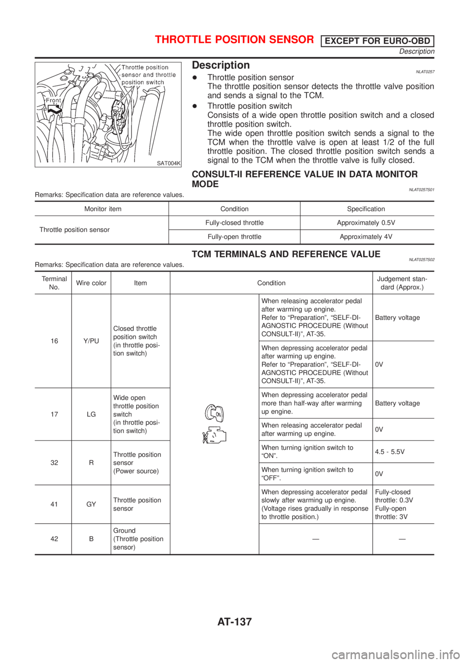
SAT004K
DescriptionNLAT0257+Throttle position sensor
The throttle position sensor detects the throttle valve position
and sends a signal to the TCM.
+Throttle position switch
Consists of a wide open throttle position switch and a closed
throttle position switch.
The wide open throttle position switch sends a signal to the
TCM when the throttle valve is open at least 1/2 of the full
throttle position. The closed throttle position switch sends a
signal to the TCM when the throttle valve is fully closed.
CONSULT-II REFERENCE VALUE IN DATA MONITOR
MODE
NLAT0257S01Remarks: Specification data are reference values.
Monitor item Condition Specification
Throttle position sensorFully-closed throttle Approximately 0.5V
Fully-open throttle Approximately 4V
TCM TERMINALS AND REFERENCE VALUENLAT0257S02Remarks: Specification data are reference values.
Terminal
No.Wire color Item ConditionJudgement stan-
dard (Approx.)
16 Y/PUClosed throttle
position switch
(in throttle posi-
tion switch)
When releasing accelerator pedal
after warming up engine.
Refer to ªPreparationº, ªSELF-DI-
AGNOSTIC PROCEDURE (Without
CONSULT-II)º, AT-35.Battery voltage
When depressing accelerator pedal
after warming up engine.
Refer to ªPreparationº, ªSELF-DI-
AGNOSTIC PROCEDURE (Without
CONSULT-II)º, AT-35.0V
17 LGWide open
throttle position
switch
(in throttle posi-
tion switch)When depressing accelerator pedal
more than half-way after warming
up engine.Battery voltage
When releasing accelerator pedal
after warming up engine.0V
32 RThrottle position
sensor
(Power source)When turning ignition switch to
ªONº.4.5 - 5.5V
When turning ignition switch to
ªOFFº.0V
41 GYThrottle position
sensorWhen depressing accelerator pedal
slowly after warming up engine.
(Voltage rises gradually in response
to throttle position.)Fully-closed
throttle: 0.3V
Fully-open
throttle: 3V
42 BGround
(Throttle position
sensor)ÐÐ
THROTTLE POSITION SENSOREXCEPT FOR EURO-OBD
Description
AT-137
Page 158 of 3051
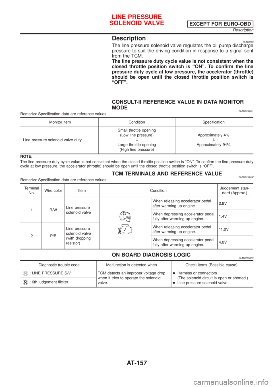
DescriptionNLAT0273The line pressure solenoid valve regulates the oil pump discharge
pressure to suit the driving condition in response to a signal sent
from the TCM.
The line pressure duty cycle value is not consistent when the
closed throttle position switch is ªONº. To confirm the line
pressure duty cycle at low pressure, the accelerator (throttle)
should be open until the closed throttle position switch is
ªOFFº.
CONSULT-II REFERENCE VALUE IN DATA MONITOR
MODE
NLAT0273S01Remarks: Specification data are reference values.
Monitor item Condition Specification
Line pressure solenoid valve dutySmall throttle opening
(Low line pressure)
¯
Large throttle opening
(High line pressure)Approximately 4%
¯
Approximately 94%
NOTE:
The line pressure duty cycle value is not consistent when the closed throttle position switch is ªONº. To confirm the line pressure duty
cycle at low pressure, the accelerator (throttle) should be open until the closed throttle position switch is ªOFFº.
TCM TERMINALS AND REFERENCE VALUENLAT0273S02Remarks: Specification data are reference values.
Terminal
No.Wire color Item ConditionJudgement stan-
dard (Approx.)
1 R/WLine pressure
solenoid valve
When releasing accelerator pedal
after warming up engine.2.8V
When depressing accelerator pedal
fully after warming up engine.1.4V
2 P/BLine pressure
solenoid valve
(with dropping
resistor)When releasing accelerator pedal
after warming up engine.11.0V
When depressing accelerator pedal
fully after warming up engine.4.0V
ON BOARD DIAGNOSIS LOGICNLAT0273S03
Diagnostic trouble code Malfunction is detected when ... Check items (Possible cause)
: LINE PRESSURE S/V TCM detects an improper voltage drop
when it tries to operate the solenoid
valve.+Harness or connectors
(The solenoid circuit is open or shorted.)
+Line pressure solenoid valve
: 6th judgement flicker
LINE PRESSURE
SOLENOID VALVE
EXCEPT FOR EURO-OBD
Description
AT-157
Page 165 of 3051
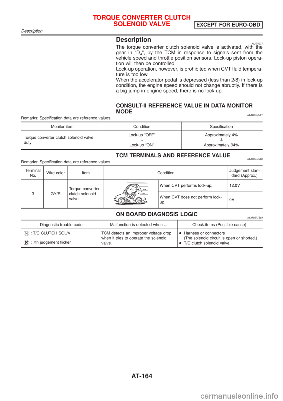
DescriptionNLAT0277The torque converter clutch solenoid valve is activated, with the
gear in ªD
4º, by the TCM in response to signals sent from the
vehicle speed and throttle position sensors. Lock-up piston opera-
tion will then be controlled.
Lock-up operation, however, is prohibited when CVT fluid tempera-
ture is too low.
When the accelerator pedal is depressed (less than 2/8) in lock-up
condition, the engine speed should not change abruptly. If there is
a big jump in engine speed, there is no lock-up.
CONSULT-II REFERENCE VALUE IN DATA MONITOR
MODE
NLAT0277S01Remarks: Specification data are reference values.
Monitor item Condition Specification
Torque converter clutch solenoid valve
dutyLock-up ªOFFº
¯
Lock-up ªONºApproximately 4%
¯
Approximately 94%
TCM TERMINALS AND REFERENCE VALUENLAT0277S02Remarks: Specification data are reference values.
Terminal
No.Wire color Item ConditionJudgement stan-
dard (Approx.)
3 GY/RTorque converter
clutch solenoid
valve
When CVT performs lock-up. 12.0V
When CVT does not perform lock-
up.0V
ON BOARD DIAGNOSIS LOGICNLAT0277S03
Diagnostic trouble code Malfunction is detected when ... Check items (Possible cause)
: T/C CLUTCH SOL/V TCM detects an improper voltage drop
when it tries to operate the solenoid
valve.+Harness or connectors
(The solenoid circuit is open or shorted.)
+T/C clutch solenoid valve
: 7th judgement flicker
TORQUE CONVERTER CLUTCH
SOLENOID VALVE
EXCEPT FOR EURO-OBD
Description
AT-164
Page 446 of 3051
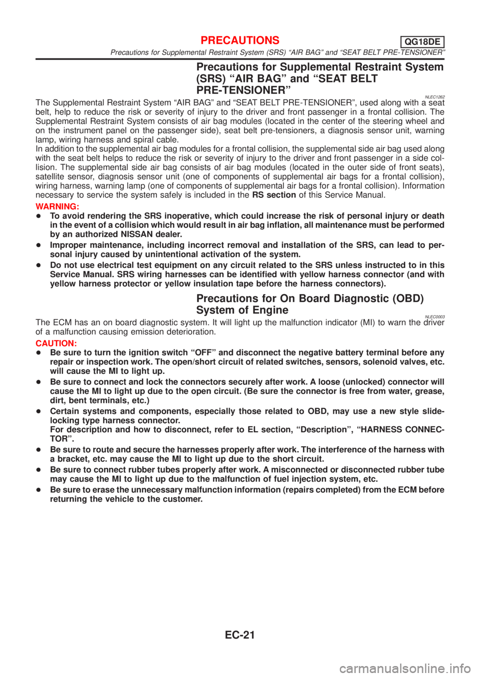
Precautions for Supplemental Restraint System
(SRS) ªAIR BAGº and ªSEAT BELT
PRE-TENSIONERº
NLEC1262The Supplemental Restraint System ªAIR BAGº and ªSEAT BELT PRE-TENSIONERº, used along with a seat
belt, help to reduce the risk or severity of injury to the driver and front passenger in a frontal collision. The
Supplemental Restraint System consists of air bag modules (located in the center of the steering wheel and
on the instrument panel on the passenger side), seat belt pre-tensioners, a diagnosis sensor unit, warning
lamp, wiring harness and spiral cable.
In addition to the supplemental air bag modules for a frontal collision, the supplemental side air bag used along
with the seat belt helps to reduce the risk or severity of injury to the driver and front passenger in a side col-
lision. The supplemental side air bag consists of air bag modules (located in the outer side of front seats),
satellite sensor, diagnosis sensor unit (one of components of supplemental air bags for a frontal collision),
wiring harness, warning lamp (one of components of supplemental air bags for a frontal collision). Information
necessary to service the system safely is included in theRS sectionof this Service Manual.
WARNING:
+To avoid rendering the SRS inoperative, which could increase the risk of personal injury or death
in the event of a collision which would result in air bag inflation, all maintenance must be performed
by an authorized NISSAN dealer.
+Improper maintenance, including incorrect removal and installation of the SRS, can lead to per-
sonal injury caused by unintentional activation of the system.
+Do not use electrical test equipment on any circuit related to the SRS unless instructed to in this
Service Manual. SRS wiring harnesses can be identified with yellow harness connector (and with
yellow harness protector or yellow insulation tape before the harness connectors).
Precautions for On Board Diagnostic (OBD)
System of Engine
NLEC0003The ECM has an on board diagnostic system. It will light up the malfunction indicator (MI) to warn the driver
of a malfunction causing emission deterioration.
CAUTION:
+Be sure to turn the ignition switch ªOFFº and disconnect the negative battery terminal before any
repair or inspection work. The open/short circuit of related switches, sensors, solenoid valves, etc.
will cause the MI to light up.
+Be sure to connect and lock the connectors securely after work. A loose (unlocked) connector will
cause the MI to light up due to the open circuit. (Be sure the connector is free from water, grease,
dirt, bent terminals, etc.)
+Certain systems and components, especially those related to OBD, may use a new style slide-
locking type harness connector.
For description and how to disconnect, refer to EL section, ªDescriptionº, ªHARNESS CONNEC-
TORº.
+Be sure to route and secure the harnesses properly after work. The interference of the harness with
a bracket, etc. may cause the MI to light up due to the short circuit.
+Be sure to connect rubber tubes properly after work. A misconnected or disconnected rubber tube
may cause the MI to light up due to the malfunction of fuel injection system, etc.
+Be sure to erase the unnecessary malfunction information (repairs completed) from the ECM before
returning the vehicle to the customer.
PRECAUTIONSQG18DE
Precautions for Supplemental Restraint System (SRS) ªAIR BAGº and ªSEAT BELT PRE-TENSIONERº
EC-21
Page 488 of 3051
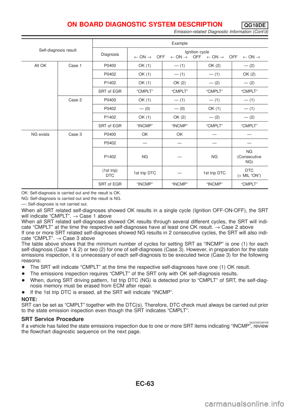
Self-diagnosis resultExample
DiagnosisIgnition cycle
¬ON®OFF¬ON®OFF¬ON®OFF¬ON®
All OK Case 1 P0400 OK (1) Ð (1) OK (2) Ð (2)
P0402 OK (1) Ð (1) Ð (1) OK (2)
P1402 OK (1) OK (2) Ð (2) Ð (2)
SRT of EGR ªCMPLTº ªCMPLTº ªCMPLTº ªCMPLTº
Case 2 P0400 OK (1) Ð (1) Ð (1) Ð (1)
P0402 Ð (0) Ð (0) OK (1) Ð (1)
P1402 OK (1) OK (2) Ð (2) Ð (2)
SRT of EGR ªINCMPº ªINCMPº ªCMPLTº ªCMPLTº
NG exists Case 3 P0400 OK OK Ð Ð
P0402ÐÐÐÐ
P1402 NG Ð NGNG
(Consecutive
NG)
(1st trip)
DTC1st trip DTC Ð 1st trip DTCDTC
(= MIL ªONº)
SRT of EGR ªINCMPº ªINCMPº ªINCMPº ªCMPLTº
OK: Self-diagnosis is carried out and the result is OK.
NG: Self-diagnosis is carried out and the result is NG.
Ð: Self-diagnosis is not carried out.
When all SRT related self-diagnoses showed OK results in a single cycle (Ignition OFF-ON-OFF), the SRT
will indicate ªCMPLTº.®Case 1 above
When all SRT related self-diagnoses showed OK results through several different cycles, the SRT will indi-
cate ªCMPLTº at the time the respective self-diagnoses have at least one OK result.®Case 2 above
If one or more SRT related self-diagnoses showed NG results in 2 consecutive cycles, the SRT will also indi-
cate ªCMPLTº.®Case 3 above
The table above shows that the minimum number of cycles for setting SRT as ªINCMPº is one (1) for each
self-diagnosis (Case1&2)ortwo(2)foroneofself-diagnoses (Case 3). However, in preparation for the state
emissions inspection, it is unnecessary of each self-diagnosis to be executed twice (Case 3) for the following
reasons:
+The SRT will indicate ªCMPLTº at the time the respective self-diagnoses have one (1) OK result.
+The emissions inspection requires ªCMPLTº of the SRT only with OK self-diagnosis results.
+When, during SRT driving pattern, 1st trip DTC (NG) is detected prior to ªCMPLTº of SRT, the self-diag-
nosis memory must be erased from ECM after repair.
+If the 1st trip DTC is erased, all the SRT will indicate ªINCMPº.
NOTE:
SRT can be set as ªCMPLTº together with the DTC(s). Therefore, DTC check must always be carried out prior
to the state emission inspection even though the SRT indicates ªCMPLTº.
SRT Service ProcedureNLEC0031S0109If a vehicle has failed the state emissions inspection due to one or more SRT items indicating ªINCMPº, review
the flowchart diagnostic sequence on the next page.
ON BOARD DIAGNOSTIC SYSTEM DESCRIPTIONQG18DE
Emission-related Diagnostic Information (Cont'd)
EC-63