2001 NISSAN ALMERA TINO BT-32
[x] Cancel search: BT-32Page 345 of 3051
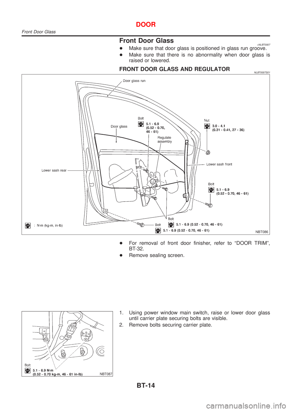
Front Door Glass=NLBT0007+Make sure that door glass is positioned in glass run groove.
+Make sure that there is no abnormality when door glass is
raised or lowered.
FRONT DOOR GLASS AND REGULATORNLBT0007S01
NBT086
+For removal of front door finisher, refer to ªDOOR TRIMº,
BT-32.
+Remove sealing screen.
NBT087
1. Using power window main switch, raise or lower door glass
until carrier plate securing bolts are visible.
2. Remove bolts securing carrier plate.
DOOR
Front Door Glass
BT-14
Page 347 of 3051
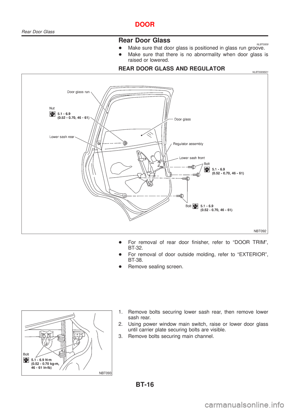
Rear Door GlassNLBT0009+Make sure that door glass is positioned in glass run groove.
+Make sure that there is no abnormality when door glass is
raised or lowered.
REAR DOOR GLASS AND REGULATORNLBT0009S01
NBT092
+For removal of rear door finisher, refer to ªDOOR TRIMº,
BT-32.
+For removal of door outside molding, refer to ªEXTERIORº,
BT-38.
+Remove sealing screen.
NBT093
1. Remove bolts securing lower sash rear, then remove lower
sash rear.
2. Using power window main switch, raise or lower door glass
until carrier plate securing bolts are visible.
3. Remove bolts securing main channel.
DOOR
Rear Door Glass
BT-16
Page 349 of 3051
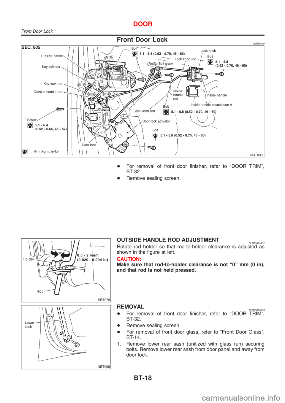
Front Door LockNLBT0010
NBT098
+For removal of front door finisher, refer to ªDOOR TRIMº,
BT-32.
+Remove sealing screen.
SBT978
OUTSIDE HANDLE ROD ADJUSTMENTNLBT0010S02Rotate rod holder so that rod-to-holder clearance is adjusted as
shown in the figure at left.
CAUTION:
Make sure that rod-to-holder clearance is not ª0º mm (0 in),
and that rod is not held pressed.
NBT099
REMOVALNLBT0010S03+For removal of front door finisher, refer to ªDOOR TRIMº,
BT-32.
+Remove sealing screen.
+For removal of front door glass, refer to ªFront Door Glassº,
BT-14.
1. Remove lower rear sash (unitized with glass run) securing
bolts. Remove lower rear sash from door panel and away from
door lock.
DOOR
Front Door Lock
BT-18
Page 351 of 3051
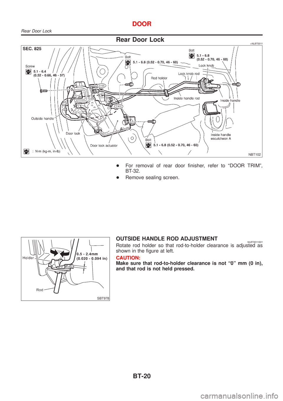
Rear Door Lock=NLBT0011
NBT102
+For removal of rear door finisher, refer to ªDOOR TRIMº,
BT-32.
+Remove sealing screen.
SBT978
OUTSIDE HANDLE ROD ADJUSTMENTNLBT0011S01Rotate rod holder so that rod-to-holder clearance is adjusted as
shown in the figure at left.
CAUTION:
Make sure that rod-to-holder clearance is not ª0º mm (0 in),
and that rod is not held pressed.
DOOR
Rear Door Lock
BT-20
Page 352 of 3051
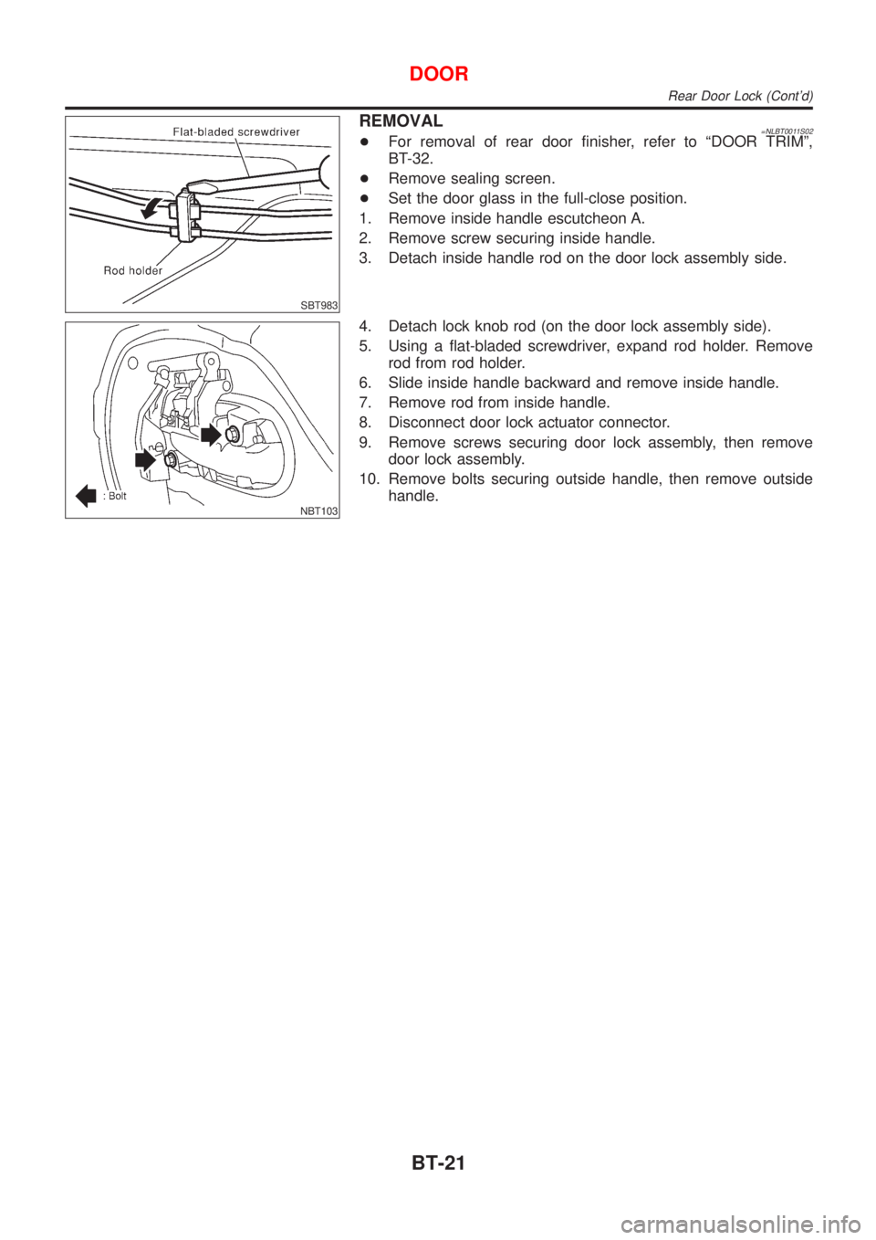
SBT983
REMOVAL=NLBT0011S02+For removal of rear door finisher, refer to ªDOOR TRIMº,
BT-32.
+Remove sealing screen.
+Set the door glass in the full-close position.
1. Remove inside handle escutcheon A.
2. Remove screw securing inside handle.
3. Detach inside handle rod on the door lock assembly side.
NBT103
4. Detach lock knob rod (on the door lock assembly side).
5. Using a flat-bladed screwdriver, expand rod holder. Remove
rod from rod holder.
6. Slide inside handle backward and remove inside handle.
7. Remove rod from inside handle.
8. Disconnect door lock actuator connector.
9. Remove screws securing door lock assembly, then remove
door lock assembly.
10. Remove bolts securing outside handle, then remove outside
handle.
DOOR
Rear Door Lock (Cont'd)
BT-21
Page 363 of 3051
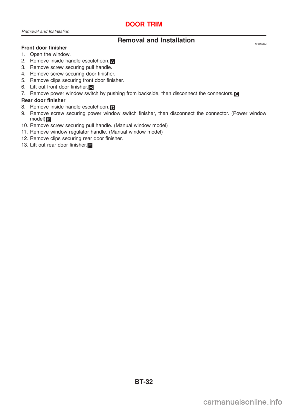
Removal and InstallationNLBT0014Front door finisher
1. Open the window.
2. Remove inside handle escutcheon.
3. Remove screw securing pull handle.
4. Remove screw securing door finisher.
5. Remove clips securing front door finisher.
6. Lift out front door finisher.
7. Remove power window switch by pushing from backside, then disconnect the connectors.
Rear door finisher
8. Remove inside handle escutcheon.
9. Remove screw securing power window switch finisher, then disconnect the connector. (Power window
model)
10. Remove screw securing pull handle. (Manual window model)
11. Remove window regulator handle. (Manual window model)
12. Remove clips securing rear door finisher.
13. Lift out rear door finisher.
DOOR TRIM
Removal and Installation
BT-32
Page 2698 of 3051
Canister - See EVAP canister .......... EC-39, 573
Charging system ....................................... SC-24
Cigarette lighter ....................................... EL-195
Circuit breaker ........................................... EL-32
Closed throttle position switch ....... EC-352, 872
Clutch cover .............................................. CL-22
Clutch disc ................................................. CL-22
Clutch master cylinder ............................... CL-11
Clutch operating cylinder ........................... CL-14
Clutch pedal .............................................. CL-10
Clutch release bearing ........................ CL-17, 20
Clutch release mechanism .................. CL-17, 20
Clutch withdrawal lever ....................... CL-17, 20
Coil spring (front) ...................................... SU-10
Coil spring (rear) ....................................... SU-23
Collision diagnosis .................................... RS-66
Combination lamp, rear, removal and
installation .............................................. BT-38
Combination meter removal and instal-
lation - See Instrument panel ................ BT-22
Combination meter .................................. EL-130
Combination switch ................................... EL-64
Compression pressure ........................... EM-164
Compressor clutch removal and
installation .............................................. HA-90
Compressor precaution ............................... HA-5
Compressor special service tool ................. HA-9
Connecting rod bearing clearance .. EM-58, 140,
232
Connecting rod bushing clearance .. EM-59, 141,
234
Connecting rod ......................... EM-55, 136, 227
Console box - See Instrument panel ......... BT-22
Control lever (M/T) .................................... MT-23
Converter housing installation ................. AT-207
Coolant mixture ratio ................................ MA-22
Cooling circuit (engine) ................. LC-12, 32, 53
Cooling fan control system ........................ LC-59
Cooling fan control ............... EC-373, 882, 1201
Cooling fan motor ........................... EC-385, 899
Cooling fan relay ............................. EC-384, 898
Coupling sleeve (M/T) ........................ MT-25, 63
Crank angle sensor built into distribu-
tor - See Camshaft position
sensor .................................................. EC-825
Crankcase emission control system -
See Positive crankcase ventilation ...... EC-42,
576, 1082
Crankcase ventilation system - See
Positive crankcase ventilation ...... EC-42, 576,
1082
Crankshaft position sensor (OBD) . EC-295, 439,
819, 969
Crankshaft position sensor (POS) .. EC-295, 439
Crankshaft position sensor (TDC) ......... EC-1166
Crankshaft ................................ EM-57, 138, 229
Cylinder block ........................... EM-52, 133, 221
Cylinder head ........................... EM-33, 108, 200D
DEF - Wiring diagram .............................. EL-199
DTC work support ............................. EC-91, 615
Data link connector for Consult ....... EC-43, 577,
1102
Daytime light system ................................. EL-73
Detonation sensor - See Knock
sensor .......................................... EC-291, 815
Diagnosis sensor unit ............................... RS-21
Diagnostic trouble code (DTC) for
OBD system ................... EC-16, 70, 550, 595,
1064, 1096
Diagnostic trouble code (DTC) inspec-
tion priority chart ......................... EC-122, 646
Differential gear (FF M/T) ............. MT-25, 63, 77
Dimensions ................................................. GI-41
Dome light - See Interior lamp ................ EL-116
Door glass ................................................. BT-14
Door lock ................................................... BT-18
Door mirror ................................................ BT-63
Door trim .................................................... BT-32
Door, front .................................................. BT-13
Door, rear ................................................... BT-13
Drive plate runout ..................... EM-60, 142, 235
Drive shaft (front) ...................................... AX-10
Dropping resistor (A/T) .................... AT-103, 163
Dual pressure switch ................................ HA-12
E
ECCS-D control module ... EC-1129, 1177, 1185,
1253, 1255, 1260, 1262
ECM input/output signal ........ EC-133, 657, 1129
ECTS - Wiring diagram ......... EC-171, 696, 1150
EGR control valve ................................... EC-400
EGR temperature sensor ................ EC-386, 915
EGR volume control valve ............ EC-319, 1277
EGR/TS - Wiring diagram ............... EC-389, 918
EGRC/V - Wiring diagram ....................... EC-322
EGRC1 - Wiring diagram ....... EC-314, 397, 449,
838, 925, 978, 1279
EVAP canister purge volume control
solenoid valve ............................... EC-40, 574
EVAP canister purge volume control
valve ............................ EC-332, 458, 852, 986
EVAP canister ................................... EC-40, 574
Electric sunroof ........................................ EL-238
Electrical diagnoses ................................... GI-21
Electrical ignition system .................. EC-37, 571
Electrical load signal circuit .......... EC-535, 1050
Electrical unit ........................................... EL-530
Electrical units location ............................ EL-442
Electronic fuel injection pump .... EC-1087, 1187,
1194, 1218, 1225, 1232, 1239, 1246, 1264
Engine compartment ................................. BT-66
Engine control circuit diagram ......... EC-30, 564,
1074
ALPHABETICAL INDEX
IDX-3