2001 NISSAN ALMERA TINO blower
[x] Cancel search: blowerPage 472 of 3051
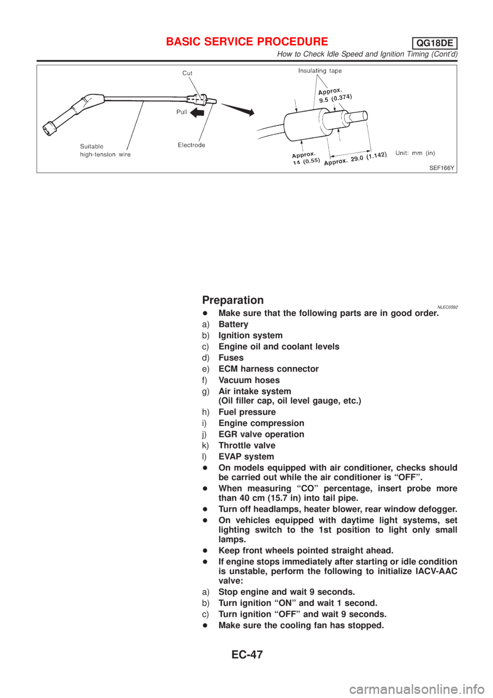
SEF166Y
PreparationNLEC0592+Make sure that the following parts are in good order.
a)Battery
b)Ignition system
c)Engine oil and coolant levels
d)Fuses
e)ECM harness connector
f)Vacuum hoses
g)Air intake system
(Oil filler cap, oil level gauge, etc.)
h)Fuel pressure
i)Engine compression
j)EGR valve operation
k)Throttle valve
l)EVAP system
+On models equipped with air conditioner, checks should
be carried out while the air conditioner is ªOFFº.
+When measuring ªCOº percentage, insert probe more
than 40 cm (15.7 in) into tail pipe.
+Turn off headlamps, heater blower, rear window defogger.
+On vehicles equipped with daytime light systems, set
lighting switch to the 1st position to light only small
lamps.
+Keep front wheels pointed straight ahead.
+If engine stops immediately after starting or idle condition
is unstable, perform the following to initialize IACV-AAC
valve:
a)Stop engine and wait 9 seconds.
b)Turn ignition ªONº and wait 1 second.
c)Turn ignition ªOFFº and wait 9 seconds.
+Make sure the cooling fan has stopped.
BASIC SERVICE PROCEDUREQG18DE
How to Check Idle Speed and Ignition Timing (Cont'd)
EC-47
Page 559 of 3051
SEF367I
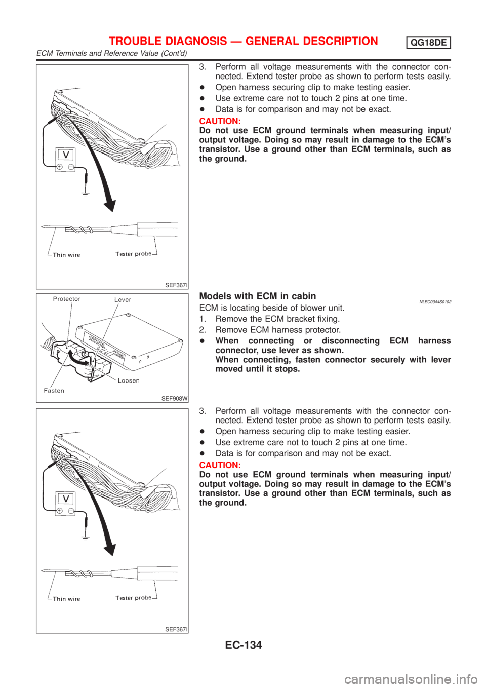
3. Perform all voltage measurements with the connector con-
nected. Extend tester probe as shown to perform tests easily.
+Open harness securing clip to make testing easier.
+Use extreme care not to touch 2 pins at one time.
+Data is for comparison and may not be exact.
CAUTION:
Do not use ECM ground terminals when measuring input/
output voltage. Doing so may result in damage to the ECM's
transistor. Use a ground other than ECM terminals, such as
the ground.
SEF908W
Models with ECM in cabinNLEC0044S0102ECM is locating beside of blower unit.
1. Remove the ECM bracket fixing.
2. Remove ECM harness protector.
+When connecting or disconnecting ECM harness
connector, use lever as shown.
When connecting, fasten connector securely with lever
moved until it stops.
SEF367I
3. Perform all voltage measurements with the connector con-
nected. Extend tester probe as shown to perform tests easily.
+Open harness securing clip to make testing easier.
+Use extreme care not to touch 2 pins at one time.
+Data is for comparison and may not be exact.
CAUTION:
Do not use ECM ground terminals when measuring input/
output voltage. Doing so may result in damage to the ECM's
transistor. Use a ground other than ECM terminals, such as
the ground.
TROUBLE DIAGNOSIS Ð GENERAL DESCRIPTIONQG18DE
ECM Terminals and Reference Value (Cont'd)
EC-134
Page 561 of 3051
![NISSAN ALMERA TINO 2001 Service Repair Manual TERMI-
NAL
NO.WIRE
COLORITEM CONDITION DATA (DC Voltage)
14 GY/LEVAP canister purge
volume control valve
(ON/OFF duty)[Engine is running]
+Warm-up condition
+Accelerator pedal depressed5 - 12V
SEF975W](/manual-img/5/57352/w960_57352-560.png "NISSAN ALMERA TINO 2001 Service Repair Manual TERMI-
NAL
NO.WIRE
COLORITEM CONDITION DATA (DC Voltage)
14 GY/LEVAP canister purge
volume control valve
(ON/OFF duty)[Engine is running]
+Warm-up condition
+Accelerator pedal depressed5 - 12V
SEF975W")
TERMI-
NAL
NO.WIRE
COLORITEM CONDITION DATA (DC Voltage)
14 GY/LEVAP canister purge
volume control valve
(ON/OFF duty)[Engine is running]
+Warm-up condition
+Accelerator pedal depressed5 - 12V
SEF975W
21 B/P Fuel pump relay[Ignition switch ªONº]
+For 1 second after turning ignition switch ªONº
[Engine is running]0-1V
[Ignition switch ªONº]
+More than 1 second after turning ignition
switch ªONºBATTERY VOLTAGE
(11 - 14V)
22 OR/L Malfunction indicator[Ignition switch ªONº]0-1V
[Engine is running]
+Idle speedBATTERY VOLTAGE
(11 - 14V)
23 L Air conditioner relay[Engine is running]
+Both A/C switch and blower switch are ªONºApproximately 0V
[Engine is running]
+A/C switch is ªOFFºBATTERY VOLTAGE
(11 - 14V)
31 W/GECM relay (Self shut-
off)[Ignition switch ªOFFº]
+For 9 seconds after turning ignition switch
ªOFFº0-1V
[Ignition switch ªOFFº]
+9 seconds passed after turning ignition switch
ªOFFºBATTERY VOLTAGE
(11 - 14V)
32 L/OR Tachometer[Engine is running]
+Warm-up condition
+Idle speed7-8V
SEF928X
[Engine is running]
+Engine speed is 2,000 rpm7-8V
SEF929X
TROUBLE DIAGNOSIS Ð GENERAL DESCRIPTIONQG18DE
ECM Terminals and Reference Value (Cont'd)
EC-136
Page 562 of 3051
![NISSAN ALMERA TINO 2001 Service Repair Manual TERMI-
NAL
NO.WIRE
COLORITEM CONDITION DATA (DC Voltage)
35
36
37
38L/W
PU
L/R
GY/RIgnition signal (No. 1)
Ignition signal (No. 2)
Ignition signal (No. 3)
Ignition signal (No. 4)[Engine is running]
+W](/manual-img/5/57352/w960_57352-561.png "NISSAN ALMERA TINO 2001 Service Repair Manual TERMI-
NAL
NO.WIRE
COLORITEM CONDITION DATA (DC Voltage)
35
36
37
38L/W
PU
L/R
GY/RIgnition signal (No. 1)
Ignition signal (No. 2)
Ignition signal (No. 3)
Ignition signal (No. 4)[Engine is running]
+W")
TERMI-
NAL
NO.WIRE
COLORITEM CONDITION DATA (DC Voltage)
35
36
37
38L/W
PU
L/R
GY/RIgnition signal (No. 1)
Ignition signal (No. 2)
Ignition signal (No. 3)
Ignition signal (No. 4)[Engine is running]
+Warm-up condition
+Idle speed0 - 0.2V
SEF971W
[Engine is running]
+Engine speed is 2,000 rpm0.2 - 0.4V
SEF972W
40 Y/PUThrottle position switch
(Closed position)
(where fitted)[Engine is running]
+Accelerator pedal releasedBATTERY VOLTAGE
(11 - 14V)
[Engine is running]
+Accelerator pedal depressedApproximately 0V
41 B/Y Start signal[Ignition switch ªONº]Approximately 0V
[Ignition switch ªSTARTº]9 - 12V
42 G/OR PNP switch[Ignition switch ªONº]
+Gear position is ªNeutral positionºApproximately 0V
[Ignition switch ªONº]
+Except the above gear positionApproximately 5V
43 B/R Ignition switch[Ignition switch ªOFFº]0V
[Ignition switch ªONº]BATTERY VOLTAGE
(11 - 14V)
44 L/R Air conditioner switch[Engine is running]
+Both air conditioner switch and blower switch
are ªONº (Compressor operates)Approximately 0V
[Engine is running]
+Air conditioner switch is ªOFFºApproximately 5V
46 PU/WPower steering oil pres-
sure switch[Engine is running]
+Steering wheel is fully turnedApproximately 0V
[Engine is running]
+Steering wheel is not turnedApproximately 5V
48 B ECM ground[Engine is running]
+Idle speedEngine ground
50 L/BElectrical load signal
(Headlamp and
Rear defogger)[Engine is running]
+Headlamp switch or rear defogger switch is
ªONºBATTERY VOLTAGE
(11 - 14V)
[Engine is running]
+Headlamp switch and rear defogger switch are
ªOFFºApproximately 0V
TROUBLE DIAGNOSIS Ð GENERAL DESCRIPTIONQG18DE
ECM Terminals and Reference Value (Cont'd)
EC-137
Page 563 of 3051
![NISSAN ALMERA TINO 2001 Service Repair Manual TERMI-
NAL
NO.WIRE
COLORITEM CONDITION DATA (DC Voltage)
51 LG/B Blower fan SW[Ignition switch ªONº]
+Blower fan switch is ªONºApproximately 0V
[Ignition switch ªONº]
+Blower fan switch is ªOFF](/manual-img/5/57352/w960_57352-562.png "NISSAN ALMERA TINO 2001 Service Repair Manual TERMI-
NAL
NO.WIRE
COLORITEM CONDITION DATA (DC Voltage)
51 LG/B Blower fan SW[Ignition switch ªONº]
+Blower fan switch is ªONºApproximately 0V
[Ignition switch ªONº]
+Blower fan switch is ªOFF")
TERMI-
NAL
NO.WIRE
COLORITEM CONDITION DATA (DC Voltage)
51 LG/B Blower fan SW[Ignition switch ªONº]
+Blower fan switch is ªONºApproximately 0V
[Ignition switch ªONº]
+Blower fan switch is ªOFFºApproximately 5V
57 B ECM ground[Engine is running]
+Idle speedEngine ground
58 B Sensors' ground[Engine is running]
+Warm-up condition
+Idle speedApproximately 0V
61 G Mass air flow sensor[Engine is running]
+Warm-up condition
+Idle speed1.0 - 1.7V
[Engine is running]
+Warm-up condition
+Engine speed is 2,500 rpm1.5 - 2.1V
62 WHeated oxygen sensor
1 (front)[Engine is running]
+Warm-up condition
+Engine speed is 2,000 rpm0 - Approximately 0.7V
SEF008W
63 LHeated oxygen sensor
2 (rear)[Engine is running]
+After warming up to normal operating tempera-
ture and engine speed is 3,000 rpm0 - Approximately 1.0V
64 Y/BIntake air temperature
sensor[Engine is running]Approximately 0 - 4.8V
Output voltage varies with
intake air temperature
66
75R
RCamshaft position sen-
sor (PHASE)[Engine is running]
+Warm-up condition
+Idle speed2.0 - 3.0V
SEF977W
[Engine is running]
+Engine speed is 2,000 rpm2.0 - 3.0V
SEF978W
67 W/LPower supply for ECM
(Back-up)[Ignition switch ªOFFº]BATTERY VOLTAGE
(11 - 14V)
70 BR/WEngine coolant tem-
perature sensor[Engine is running]Approximately 0 - 4.8V
Output voltage varies with
engine coolant temperature
TROUBLE DIAGNOSIS Ð GENERAL DESCRIPTIONQG18DE
ECM Terminals and Reference Value (Cont'd)
EC-138
Page 799 of 3051
ECM Terminals and Reference Value=NLEC0487Specification data are reference values and are measured between each terminal and ground.
CAUTION:
Do not use ECM ground terminals when measuring input/output voltage. Doing so may result in dam-
age to the ECM's transistor. Use a ground other than ECM terminals, such as the ground.
TERMI-
NAL
NO.WIRE
COLORITEM CONDITION DATA (DC Voltage)
13 LG/R Cooling fan relay[Engine is running]
+Cooling fan is not operatingBATTERY VOLTAGE
(11 - 14V)
[Engine is running]
+Cooling fan is operating0 - 0.6V
23 L/W Air conditioner switch[Engine is running]
+Both air conditioner switch and blower switch are
ªONº (Compressor operates)Approximately 0V
[Engine is running]
+Air conditioner switch is ªOFFºBATTERY VOLTAGE
(11 - 14V)
On Board Diagnosis LogicNLEC0572If the cooling fan or another component in the cooling system malfunctions, engine coolant temperature will
rise.
When the engine coolant temperature reaches an abnormally high temperature condition, a malfunction is
indicated.
DTC No. Malfunction is detected when ... Check Items (Possible Cause)
P1217
1217+The engine coolant temperature is extraordinary high,
even when the load is not heavy.+Harness or connectors
(The cooling fan circuit is open or shorted)
+Cooling fan
+Thermostat
+Improper ignition timing
+Engine coolant temperature sensor
+Blocked radiator
+Blocked front end (Improper fitting of nose mask)
+Crushed vehicle frontal area (Vehicle frontal is
collided but not repaired)
+Blocked air passage by improper installation of
front fog lamp or fog lamps.
+Improper mixture ratio of coolant
+Damaged bumper
For more information, refer to ªMAIN 12 CAUSES
OF OVERHEATINGº, EC-384.
CAUTION:
When a malfunction is indicated, be sure to replace the coolant following the procedure in the LC-19,
ªChanging Engine Coolantº. Also, replace the engine oil.
1) Fill radiator with coolant up to specified level with a filling speed of 2 liters per minute. Be sure to use
coolant with the proper mixture ratio. Refer to MA-20, ªAnti-freeze Coolant Mixture Ratioº, ªRECOM-
MENDED FLUIDS AND LUBRICANTSº.
2) After refilling coolant, run engine to ensure that no water-flow noise is emitted.
DTC P1217 OVERHEAT (COOLING SYSTEM)QG18DE
ECM Terminals and Reference Value
EC-374
Page 800 of 3051
SEF621WA
SEF646X
SEC163BA
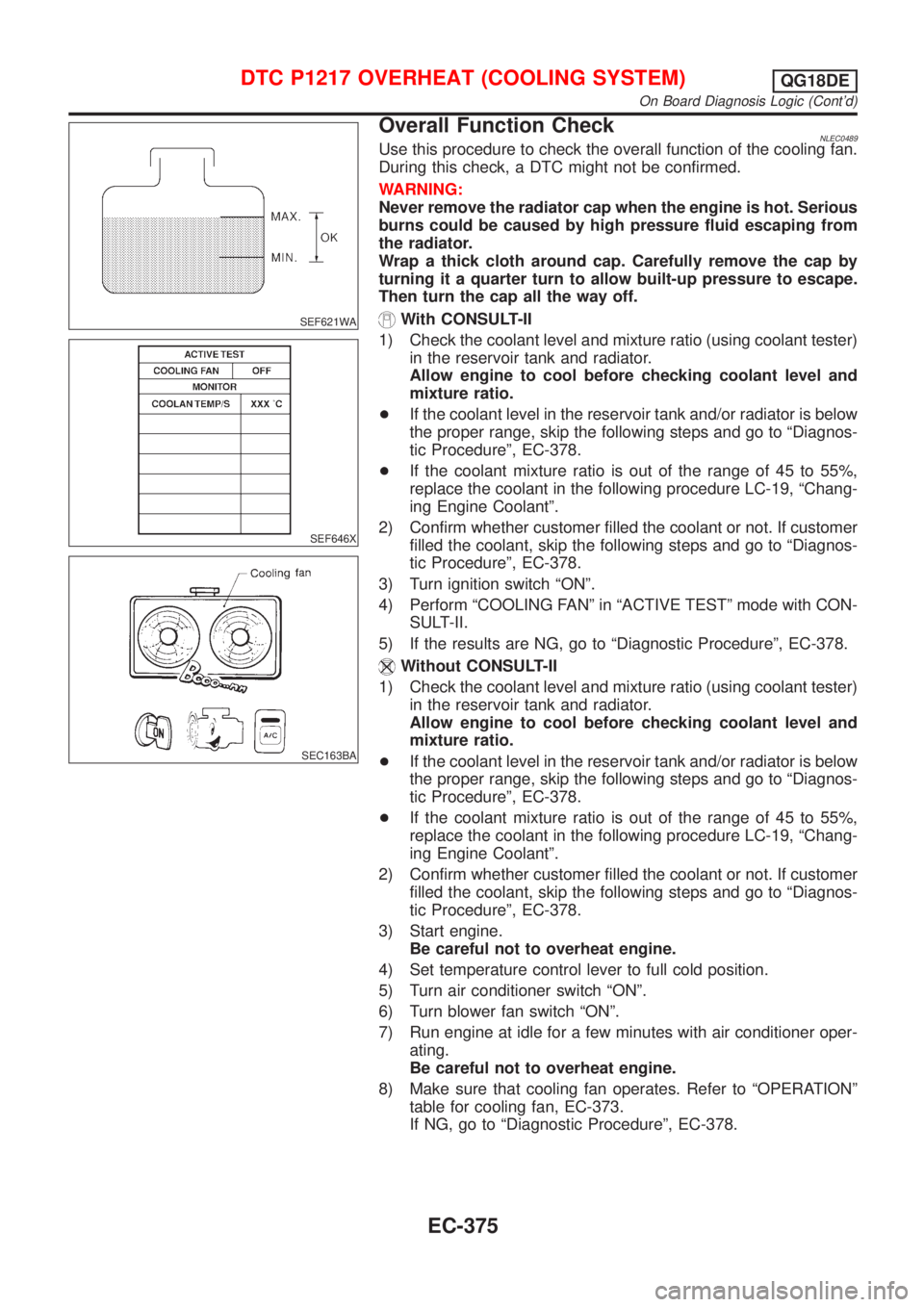
Overall Function CheckNLEC0489Use this procedure to check the overall function of the cooling fan.
During this check, a DTC might not be confirmed.
WARNING:
Never remove the radiator cap when the engine is hot. Serious
burns could be caused by high pressure fluid escaping from
the radiator.
Wrap a thick cloth around cap. Carefully remove the cap by
turning it a quarter turn to allow built-up pressure to escape.
Then turn the cap all the way off.
With CONSULT-II
1) Check the coolant level and mixture ratio (using coolant tester)
in the reservoir tank and radiator.
Allow engine to cool before checking coolant level and
mixture ratio.
+If the coolant level in the reservoir tank and/or radiator is below
the proper range, skip the following steps and go to ªDiagnos-
tic Procedureº, EC-378.
+If the coolant mixture ratio is out of the range of 45 to 55%,
replace the coolant in the following procedure LC-19, ªChang-
ing Engine Coolantº.
2) Confirm whether customer filled the coolant or not. If customer
filled the coolant, skip the following steps and go to ªDiagnos-
tic Procedureº, EC-378.
3) Turn ignition switch ªONº.
4) Perform ªCOOLING FANº in ªACTIVE TESTº mode with CON-
SULT-II.
5) If the results are NG, go to ªDiagnostic Procedureº, EC-378.
Without CONSULT-II
1) Check the coolant level and mixture ratio (using coolant tester)
in the reservoir tank and radiator.
Allow engine to cool before checking coolant level and
mixture ratio.
+If the coolant level in the reservoir tank and/or radiator is below
the proper range, skip the following steps and go to ªDiagnos-
tic Procedureº, EC-378.
+If the coolant mixture ratio is out of the range of 45 to 55%,
replace the coolant in the following procedure LC-19, ªChang-
ing Engine Coolantº.
2) Confirm whether customer filled the coolant or not. If customer
filled the coolant, skip the following steps and go to ªDiagnos-
tic Procedureº, EC-378.
3) Start engine.
Be careful not to overheat engine.
4) Set temperature control lever to full cold position.
5) Turn air conditioner switch ªONº.
6) Turn blower fan switch ªONº.
7) Run engine at idle for a few minutes with air conditioner oper-
ating.
Be careful not to overheat engine.
8) Make sure that cooling fan operates. Refer to ªOPERATIONº
table for cooling fan, EC-373.
If NG, go to ªDiagnostic Procedureº, EC-378.
DTC P1217 OVERHEAT (COOLING SYSTEM)QG18DE
On Board Diagnosis Logic (Cont'd)
EC-375
Page 803 of 3051
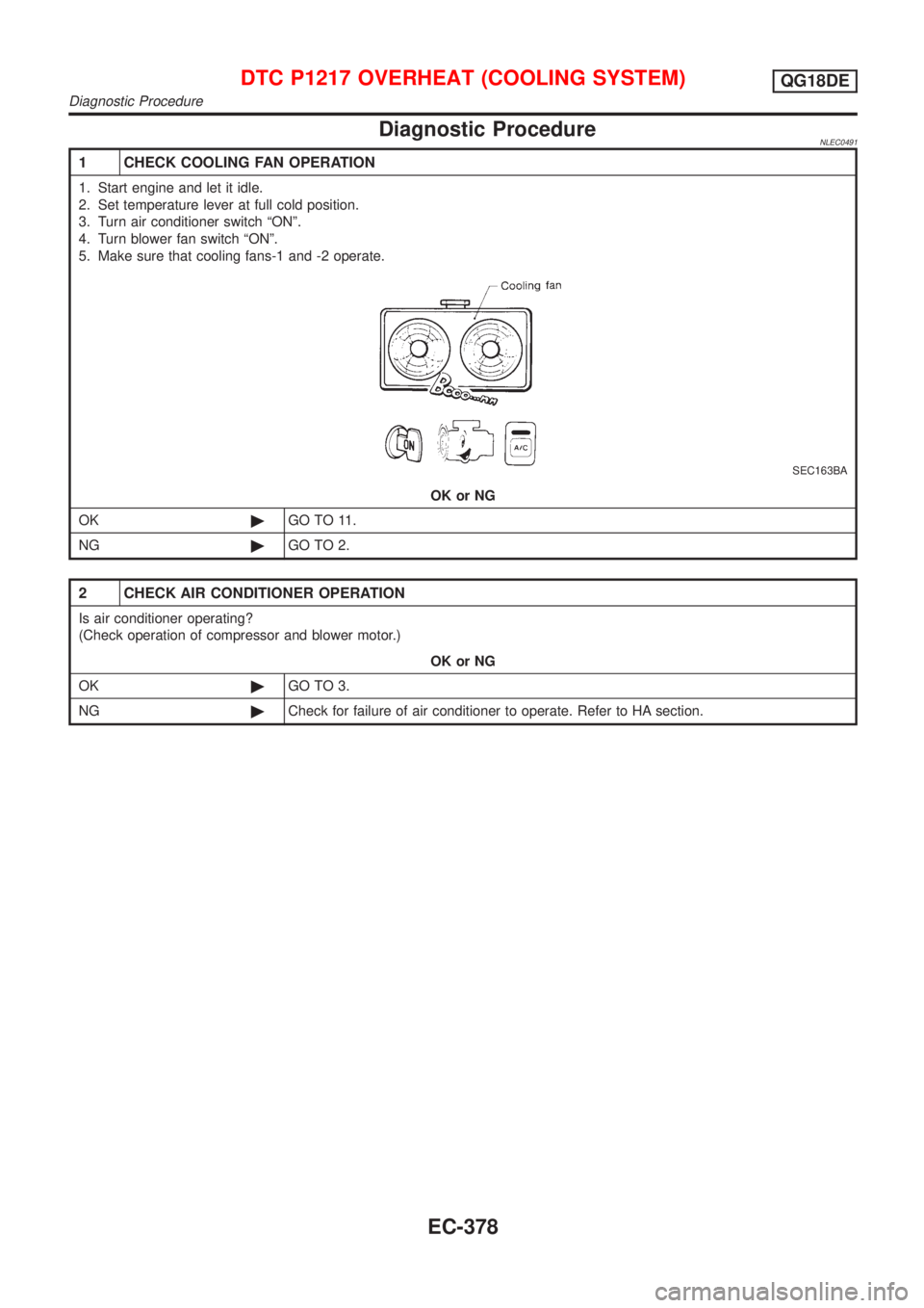
Diagnostic ProcedureNLEC0491
1 CHECK COOLING FAN OPERATION
1. Start engine and let it idle.
2. Set temperature lever at full cold position.
3. Turn air conditioner switch ªONº.
4. Turn blower fan switch ªONº.
5. Make sure that cooling fans-1 and -2 operate.
SEC163BA
OK or NG
OK©GO TO 11.
NG©GO TO 2.
2 CHECK AIR CONDITIONER OPERATION
Is air conditioner operating?
(Check operation of compressor and blower motor.)
OK or NG
OK©GO TO 3.
NG©Check for failure of air conditioner to operate. Refer to HA section.
DTC P1217 OVERHEAT (COOLING SYSTEM)QG18DE
Diagnostic Procedure
EC-378