2001 NISSAN ALMERA TINO steering system
[x] Cancel search: steering systemPage 1 of 3051

Release:April 2001 01)GENERALINFORMATIONGIMAINTENANCEMAENGINEMECHANICALEMENGINELUBRICATION&
COOLINGSYSTEMSLCENGINECONTROLSYSTEMECACCELERATORCONTROL,
FUEL&EXHAUSTSYSTEMSFECLUTCHCLMANUALTRANSAXLEMTAUTOMATICTRANSAXLEATFRONT&REARAXLEAXFRONT&REARSUSPENSIONSUBRAKESYSTEMBRSTEERINGSYSTEMSTRESTRAINTSYSTEMRSBODY&TRIMBTHEATER&AIRCONDITIONERHASTARTING&CHARGINGSYSTEMSSCELECTRICALSYSTEMELALPHABETICALINDEXIDXALMERATINOMODELV10SERIESQUICKREFERENCEINDEX
Page 7 of 3051

Precautions for Supplemental Restraint System
(SRS) ªAIR BAGº and ªSEAT BELT
PRE-TENSIONERº
NLAT0002The Supplemental Restraint System ªAIR BAGº and ªSEAT BELT PRE-TENSIONERº, used along with a seat
belt, help to reduce the risk or severity of injury to the driver and front passenger in a frontal collision. The
Supplemental Restraint System consists of air bag modules (located in the center of the steering wheel and
on the instrument panel on the passenger side), seat belt pre-tensioners, a diagnosis sensor unit, warning
lamp, wiring harness and spiral cable.
In addition to the supplemental air bag modules for a frontal collision, the supplemental side air bag used along
with the seat belt helps to reduce the risk or severity of injury to the driver and front passenger in a side col-
lision. The supplemental side air bag consists of air bag modules (located in the outer side of front seats),
satellite sensor, diagnosis sensor unit (one of components of supplemental air bags for a frontal collision),
wiring harness, warning lamp (one of components of supplemental air bags for a frontal collision). Information
necessary to service the system safely is included in theRS sectionof this Service Manual.
WARNING:
+To avoid rendering the SRS inoperative, which could increase the risk of personal injury or death
in the event of a collision which would result in air bag inflation, all maintenance must be performed
by an authorized NISSAN dealer.
+Improper maintenance, including incorrect removal and installation of the SRS, can lead to per-
sonal injury caused by unintentional activation of the system.
+Do not use electrical test equipment on any circuit related to the SRS unless instructed to in this
Service Manual. SRS wiring harnesses can be identified with yellow harness connector (and with
yellow harness protector or yellow insulation tape before the harness connectors).
Precautions for On Board Diagnostic (EURO-
OBD) System of CVT and Engine
NLAT0198The ECM has an on board diagnostic system. It will light up the malfunction indicator lamp (MI) to warn the
driver of a malfunction causing emission deterioration.
CAUTION:
+Be sure to turn the ignition switch ªOFFº and disconnect the negative battery terminal before any
repair or inspection work. The open/short circuit of related switches, sensors, solenoid valves, etc.
will cause the MI to light up.
+Be sure to connect and lock the connectors securely after work. A loose (unlocked) connector will
cause the MI to light up due to an open circuit. (Be sure the connector is free from water, grease,
dirt, bent terminals, etc.)
+Be sure to route and secure the harnesses properly after work. Interference of the harness with a
bracket, etc. may cause the MI to light up due to a short circuit.
+Be sure to connect rubber tubes properly after work. A misconnected or disconnected rubber tube
may cause the MI to light up due to a malfunction of the EGR system or fuel injection system, etc.
+Be sure to erase the unnecessary malfunction information (repairs completed) from the TCM and
ECM before returning the vehicle to the customer.
SEF289H
PrecautionsNLAT0003+Before connecting or disconnecting the TCM harness
connector, turn ignition switch OFF and disconnect nega-
tive battery terminal. Failure to do so may damage the
TCM. Because battery voltage is applied to TCM even if
ignition switch is turned off.
PRECAUTIONS
Precautions for Supplemental Restraint System (SRS) ªAIR BAGº and ªSEAT BELT PRE-TENSIONERº
AT-6
Page 279 of 3051

PurposeNLBR0082The ABS consists of electronic and hydraulic components. It allows to control the braking force so that lock-
ing of the wheels can be avoided.
The ABS:
1) Ensures proper tracking performance through steering wheel operation.
2) Enables obstacles to be avoided through steering wheel operation.
3) Ensures vehicle stability by preventing flat spins.
ABS (Anti-Lock Brake System) OperationNLBR0083+When the vehicle speed is less than 10 km/h (6 MPH) this system does not work.
+The Anti-Lock Brake System (ABS) has self-test capabilities. The system turns on the ABS warning lamp
for 1 second after turning the ignition switch ON. The system performs another test the first time the vehicle
reaches 6 km/h (4 MPH). A mechanical noise may be heard as the ABS performs a self-test. This is a
normal part of the self-test feature. If a malfunction is found during this check, the ABS warning lamp will
come on.
+During ABS operation, a mechanical noise may be heard. This is a normal condition.
ABS Hydraulic CircuitNLBR0084
SBR757E
1. Inlet solenoid valve
2. Outlet solenoid valve
3. Reservoir4. Pump
5. Motor6. Bypass check valve
7. Damper
DESCRIPTIONABS
Purpose
BR-42
Page 410 of 3051
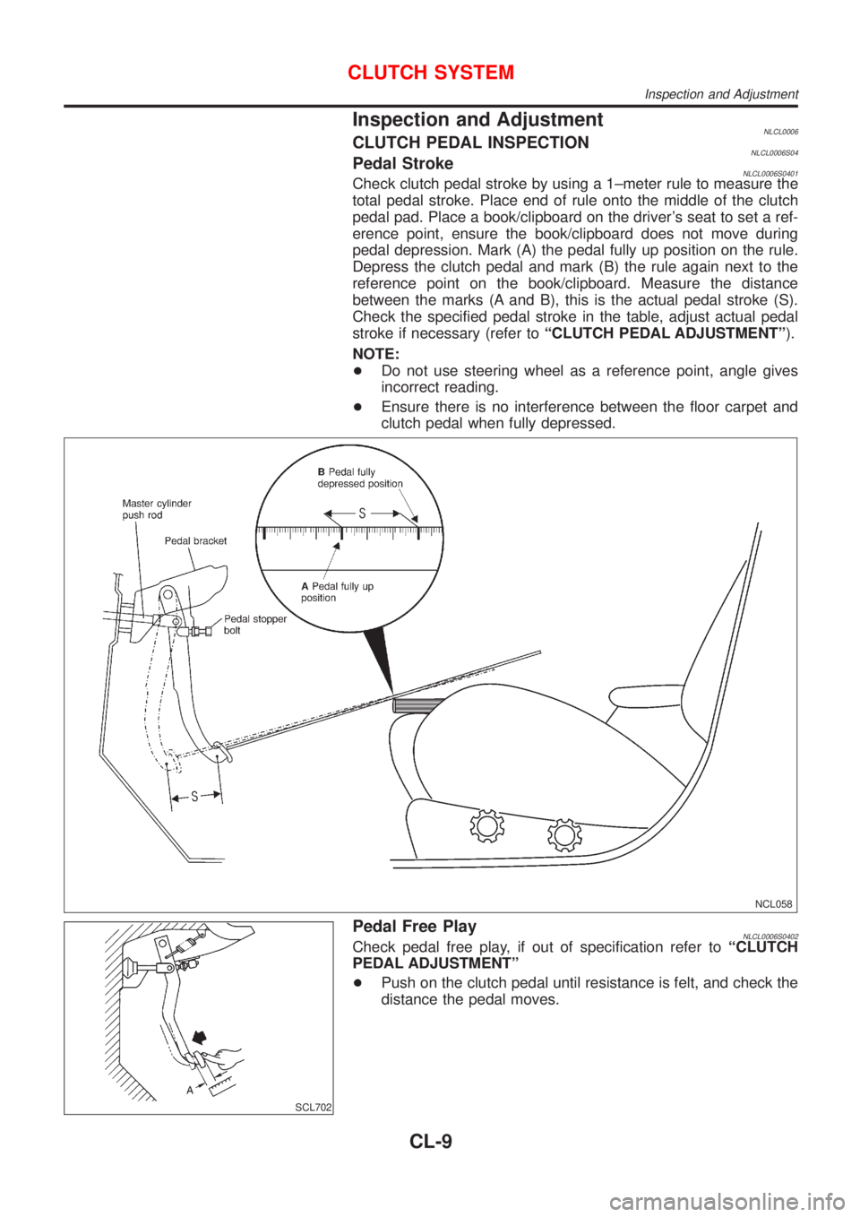
Inspection and AdjustmentNLCL0006CLUTCH PEDAL INSPECTIONNLCL0006S04Pedal StrokeNLCL0006S0401Check clutch pedal stroke by using a 1±meter rule to measure the
total pedal stroke. Place end of rule onto the middle of the clutch
pedal pad. Place a book/clipboard on the driver's seat to set a ref-
erence point, ensure the book/clipboard does not move during
pedal depression. Mark (A) the pedal fully up position on the rule.
Depress the clutch pedal and mark (B) the rule again next to the
reference point on the book/clipboard. Measure the distance
between the marks (A and B), this is the actual pedal stroke (S).
Check the specified pedal stroke in the table, adjust actual pedal
stroke if necessary (refer toªCLUTCH PEDAL ADJUSTMENTº).
NOTE:
+Do not use steering wheel as a reference point, angle gives
incorrect reading.
+Ensure there is no interference between the floor carpet and
clutch pedal when fully depressed.
NCL058
SCL702
Pedal Free PlayNLCL0006S0402Check pedal free play, if out of specification refer toªCLUTCH
PEDAL ADJUSTMENTº
+Push on the clutch pedal until resistance is felt, and check the
distance the pedal moves.
CLUTCH SYSTEM
Inspection and Adjustment
CL-9
Page 431 of 3051
CONSULT-II Reference Value in Data Monitor
Mode ........................................................................467
ECM Terminals and Reference Value .....................467
Wiring Diagram ........................................................468
Diagnostic Procedure ..............................................470
Component Inspection .............................................474
INTAKE VALVE TIMING CONTROL SOLENOID
VALVE..........................................................................475
Component Description ...........................................475
Operation .................................................................475
CONSULT-II Reference Value in Data Monitor
Mode ........................................................................475
ECM Terminals and Reference Value .....................475
Wiring Diagram ........................................................476
Diagnostic Procedure ..............................................478
Component Inspection .............................................480
SWIRL CONTROL VALVE CONTROL SYSTEM
(WHERE FITTED)........................................................481
Description ...............................................................481
CONSULT-II Reference Value in Data Monitor
Mode ........................................................................481
ECM Terminals and Reference Value .....................482
Component Description ...........................................482
Wiring Diagram ........................................................483
Diagnostic Procedure ..............................................484
Component Inspection .............................................488
PARK/NEUTRAL POSITION (PNP) SWITCH............490
Component Description ...........................................490
CONSULT-II Reference Value in Data Monitor
Mode ........................................................................490
ECM Terminals and Reference Value .....................490
Wiring Diagram ........................................................491
Diagnostic Procedure ..............................................492
INJECTOR...................................................................494
Component Description ...........................................494
CONSULT-II Reference Value in Data Monitor
Mode ........................................................................494
ECM Terminals and Reference Value .....................494
Wiring Diagram ........................................................495
Diagnostic Procedure ..............................................497
Component Inspection .............................................499
IGNITION SIGNAL.......................................................500
Component Description ...........................................500
CONSULT-II Reference Value in Data Monitor
Mode ........................................................................500
ECM Terminals and Reference Value .....................500
Wiring Diagram ........................................................501
Diagnostic Procedure ..............................................505
Component Inspection .............................................509
START SIGNAL........................................................... 511
CONSULT-II Reference Value in Data Monitor
Mode ........................................................................ 511ECM Terminals and Reference Value ..................... 511
Wiring Diagram ........................................................512
Diagnostic Procedure ..............................................514
FUEL PUMP.................................................................516
System Description ..................................................516
Component Description ...........................................516
CONSULT-II Reference Value in Data Monitor
Mode ........................................................................516
ECM Terminals and Reference Value .....................517
Wiring Diagram ........................................................518
Diagnostic Procedure ..............................................520
Component Inspection .............................................522
POWER STEERING OIL PRESSURE SWITCH.........523
Component Description ...........................................523
CONSULT-II Reference Value in Data Monitor
Mode ........................................................................523
ECM Terminals and Reference Value .....................523
Wiring Diagram ........................................................524
Diagnostic Procedure ..............................................526
Component Inspection .............................................527
REFRIGERANT PRESSURE SENSOR......................529
Description ...............................................................529
ECM Terminals and Reference Value .....................529
Wiring Diagram ........................................................530
Diagnostic Procedure ..............................................532
ELECTRICAL LOAD SIGNAL.....................................535
CONSULT-II Reference Value in Data Monitor
Mode ........................................................................535
ECM Terminals and Reference Value .....................535
Wiring Diagram ........................................................536
Diagnostic Procedure - Load Signal - .....................540
Diagnostic Procedure - Heater Control Panel
(Fan Switch) - ..........................................................544
MI & DATA LINK CONNECTORS..............................545
Wiring Diagram ........................................................545
SERVICE DATA AND SPECIFICATIONS (SDS).......547
Fuel Pressure Regulator..........................................547
Idle Speed and Ignition Timing ................................547
Mass Air Flow Sensor..............................................547
Intake Air Temperature Sensor ................................547
Engine Coolant Temperature Sensor ......................547
Throttle Position Sensor ..........................................547
Heated Oxygen Sensor 1 Heater (Front) ................547
Heated Oxygen Sensor 2 Heater (Rear).................547
EGR Volume Control Valve (where fitted) ...............548
EGR Temperature Sensor (where fitted) .................548
EVAP Canister Purge Volume Control Valve ..........548
IACV-AAC Valve ......................................................548
Injector .....................................................................548
Ignition Coil with Power Transistor ..........................548
Condenser ...............................................................548
Fuel Pump ...............................................................548
CONTENTS(Cont'd)
EC-6
Page 437 of 3051
Diagnostic Procedure ............................................1019
INJECTOR.................................................................1021
Component Description .........................................1021
CONSULT-II Reference Value in Data Monitor
Mode ......................................................................1021
ECM Terminals and Reference Value ...................1021
Wiring Diagram ......................................................1022
Diagnostic Procedure ............................................1024
Component Inspection ...........................................1026
START SIGNAL.........................................................1027
CONSULT-II Reference Value in Data Monitor
Mode ......................................................................1027
ECM Terminals and Reference Value ...................1027
Wiring Diagram ......................................................1028
Diagnostic Procedure ............................................1030
FUEL PUMP...............................................................1032
System Description ................................................1032
Component Description .........................................1032
CONSULT-II Reference Value in Data Monitor
Mode ......................................................................1032
ECM Terminals and Reference Value ...................1033
Wiring Diagram ......................................................1034
Diagnostic Procedure ............................................1036
Component Inspection ...........................................1038
POWER STEERING OIL PRESSURE SWITCH.......1039
Component Description .........................................1039
CONSULT-II Reference Value in Data Monitor
Mode ......................................................................1039
ECM Terminals and Reference Value ...................1039
Wiring Diagram ......................................................1040
Diagnostic Procedure ............................................1041
Component Inspection ...........................................1043
REFRIGERANT PRESSURE SENSOR....................1044
Description .............................................................1044
ECM Terminals and Reference Value ...................1044
Wiring Diagram ......................................................1045
Diagnostic Procedure ............................................1047
ELECTRICAL LOAD SIGNAL...................................1050
CONSULT-II Reference Value in Data Monitor
Mode ......................................................................1050
ECM Terminals and Reference Value ...................1050
Wiring Diagram ......................................................1051
Diagnostic Procedure - Load Signal - ...................1055
Diagnostic Procedure - Heater Control Panel
(Fan Switch) - ........................................................1059
MI & DATA LINK CONNECTORS............................1060
Wiring Diagram ......................................................1060
SERVICE DATA AND SPECIFICATIONS (SDS).....1062
Fuel Pressure Regulator........................................1062
Idle Speed and Ignition Timing ..............................1062
Ignition Coil ............................................................1062
Mass Air Flow Sensor............................................1062Engine Coolant Temperature Sensor ....................1062
EGR Volume Control Valve (where fitted) .............1062
EGR Temperature Sensor (where fitted) ...............1062
Fuel Pump .............................................................1063
IACV-AAC Valve ....................................................1063
Injector ...................................................................1063
Resistor ..................................................................1063
Throttle Position Sensor ........................................1063
Heated Oxygen Sensor 1 (Front) Heater ..............1063
Intake Air Temperature Sensor ..............................1063
EVAP Canister Purge Volume Control Valve ........1063
Heated Oxygen Sensor 2 (Rear) Heater...............1063
Crankshaft Position Sensor (OBD)........................1063
YD22DDTI
TROUBLE DIAGNOSIS - INDEX..............................1064
Alphabetical & P No. Index for DTC .....................1064
PRECAUTIONS.........................................................1066
Precautions for Supplemental Restraint System
(SRS)²AIR BAG²and²SEAT BELT
PRE-TENSIONER²................................................1066
Engine Fuel & Emission Control System ..............1066
Wiring Diagrams and Trouble Diagnosis ...............1069
PREPARATION.........................................................1070
Special Service Tools ............................................1070
ENGINE AND EMISSION CONTROL OVERALL
SYSTEM.....................................................................1071
Engine Control Component Parts Location ...........1071
Circuit Diagram ......................................................1074
System Diagram ....................................................1076
Vacuum Hose Drawing ..........................................1077
System Chart .........................................................1078
ENGINE AND EMISSION BASIC CONTROL
SYSTEM DESCRIPTION...........................................1079
Fuel Injection Control System ...............................1079
Fuel Injection Timing Control System....................1080
Air Conditioning Cut Control ..................................1081
Fuel Cut Control (at no load & high engine
speed) ....................................................................1081
Crankcase Ventilation System ...............................1082
BASIC SERVICE PROCEDURE...............................1083
Injection Tube and Injection Nozzle ......................1083
Electronic Control Fuel Injection Pump .................1087
Fuel Filter ...............................................................1094
ON BOARD DIAGNOSTIC SYSTEM
DESCRIPTION...........................................................1096
DTC and MI Detection Logic .................................1096
Diagnostic Trouble Code (DTC) ............................1096
NATS (Nissan Anti-Theft System) .........................1097
Malfunction Indicator (MI) ......................................1097
CONSULT-II ........................................................... 1102
CONTENTS(Cont'd)
EC-12
Page 446 of 3051
Precautions for Supplemental Restraint System
(SRS) ªAIR BAGº and ªSEAT BELT
PRE-TENSIONERº
NLEC1262The Supplemental Restraint System ªAIR BAGº and ªSEAT BELT PRE-TENSIONERº, used along with a seat
belt, help to reduce the risk or severity of injury to the driver and front passenger in a frontal collision. The
Supplemental Restraint System consists of air bag modules (located in the center of the steering wheel and
on the instrument panel on the passenger side), seat belt pre-tensioners, a diagnosis sensor unit, warning
lamp, wiring harness and spiral cable.
In addition to the supplemental air bag modules for a frontal collision, the supplemental side air bag used along
with the seat belt helps to reduce the risk or severity of injury to the driver and front passenger in a side col-
lision. The supplemental side air bag consists of air bag modules (located in the outer side of front seats),
satellite sensor, diagnosis sensor unit (one of components of supplemental air bags for a frontal collision),
wiring harness, warning lamp (one of components of supplemental air bags for a frontal collision). Information
necessary to service the system safely is included in theRS sectionof this Service Manual.
WARNING:
+To avoid rendering the SRS inoperative, which could increase the risk of personal injury or death
in the event of a collision which would result in air bag inflation, all maintenance must be performed
by an authorized NISSAN dealer.
+Improper maintenance, including incorrect removal and installation of the SRS, can lead to per-
sonal injury caused by unintentional activation of the system.
+Do not use electrical test equipment on any circuit related to the SRS unless instructed to in this
Service Manual. SRS wiring harnesses can be identified with yellow harness connector (and with
yellow harness protector or yellow insulation tape before the harness connectors).
Precautions for On Board Diagnostic (OBD)
System of Engine
NLEC0003The ECM has an on board diagnostic system. It will light up the malfunction indicator (MI) to warn the driver
of a malfunction causing emission deterioration.
CAUTION:
+Be sure to turn the ignition switch ªOFFº and disconnect the negative battery terminal before any
repair or inspection work. The open/short circuit of related switches, sensors, solenoid valves, etc.
will cause the MI to light up.
+Be sure to connect and lock the connectors securely after work. A loose (unlocked) connector will
cause the MI to light up due to the open circuit. (Be sure the connector is free from water, grease,
dirt, bent terminals, etc.)
+Certain systems and components, especially those related to OBD, may use a new style slide-
locking type harness connector.
For description and how to disconnect, refer to EL section, ªDescriptionº, ªHARNESS CONNEC-
TORº.
+Be sure to route and secure the harnesses properly after work. The interference of the harness with
a bracket, etc. may cause the MI to light up due to the short circuit.
+Be sure to connect rubber tubes properly after work. A misconnected or disconnected rubber tube
may cause the MI to light up due to the malfunction of fuel injection system, etc.
+Be sure to erase the unnecessary malfunction information (repairs completed) from the ECM before
returning the vehicle to the customer.
PRECAUTIONSQG18DE
Precautions for Supplemental Restraint System (SRS) ªAIR BAGº and ªSEAT BELT PRE-TENSIONERº
EC-21
Page 459 of 3051
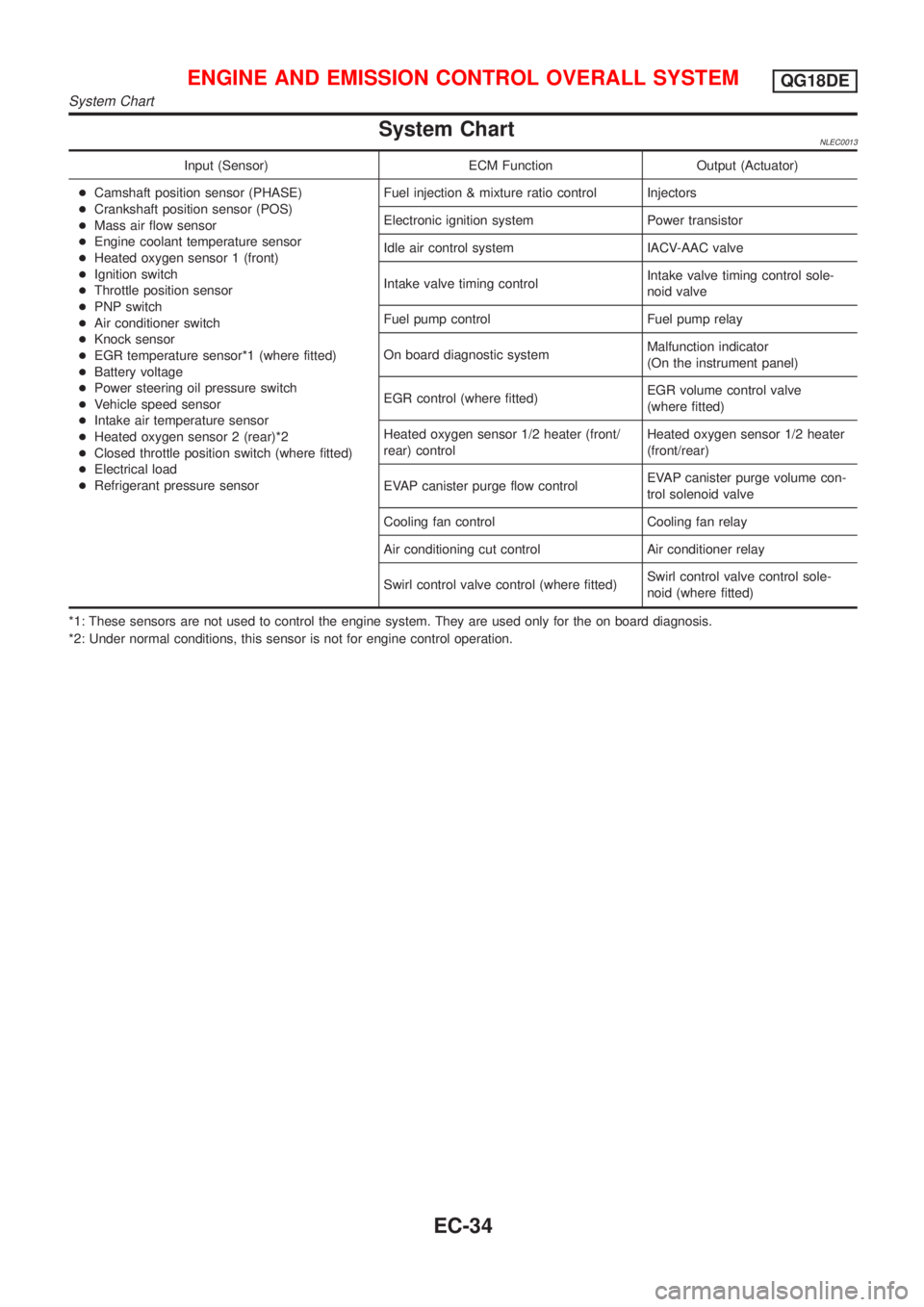
System ChartNLEC0013
Input (Sensor) ECM Function Output (Actuator)
+Camshaft position sensor (PHASE)
+Crankshaft position sensor (POS)
+Mass air flow sensor
+Engine coolant temperature sensor
+Heated oxygen sensor 1 (front)
+Ignition switch
+Throttle position sensor
+PNP switch
+Air conditioner switch
+Knock sensor
+EGR temperature sensor*1 (where fitted)
+Battery voltage
+Power steering oil pressure switch
+Vehicle speed sensor
+Intake air temperature sensor
+Heated oxygen sensor 2 (rear)*2
+Closed throttle position switch (where fitted)
+Electrical load
+Refrigerant pressure sensorFuel injection & mixture ratio control Injectors
Electronic ignition system Power transistor
Idle air control system IACV-AAC valve
Intake valve timing controlIntake valve timing control sole-
noid valve
Fuel pump control Fuel pump relay
On board diagnostic systemMalfunction indicator
(On the instrument panel)
EGR control (where fitted)EGR volume control valve
(where fitted)
Heated oxygen sensor 1/2 heater (front/
rear) controlHeated oxygen sensor 1/2 heater
(front/rear)
EVAP canister purge flow controlEVAP canister purge volume con-
trol solenoid valve
Cooling fan control Cooling fan relay
Air conditioning cut control Air conditioner relay
Swirl control valve control (where fitted)Swirl control valve control sole-
noid (where fitted)
*1: These sensors are not used to control the engine system. They are used only for the on board diagnosis.
*2: Under normal conditions, this sensor is not for engine control operation.
ENGINE AND EMISSION CONTROL OVERALL SYSTEMQG18DE
System Chart
EC-34