2001 NISSAN ALMERA TINO alternator belt
[x] Cancel search: alternator beltPage 2424 of 3051
+If the belt deflection of the current belt is out of the ªLimit
for re-tighteningº, adjust to the ªAdjusted valueº.
+When checking belt deflection immediately after
installation, first adjust it to the specified value. Then,
after turning crankshaft two turns or more, re-adjust it to
the specified value to avoid variation in deflection
between pulleys.
+Make sure the belts are fully fitted into the pulley grooves
during installation.
+Handle with care to avoid smearing the belts with oil or
cooling water etc.
+Do not twist or bend the belts with strong force.
JEM251G
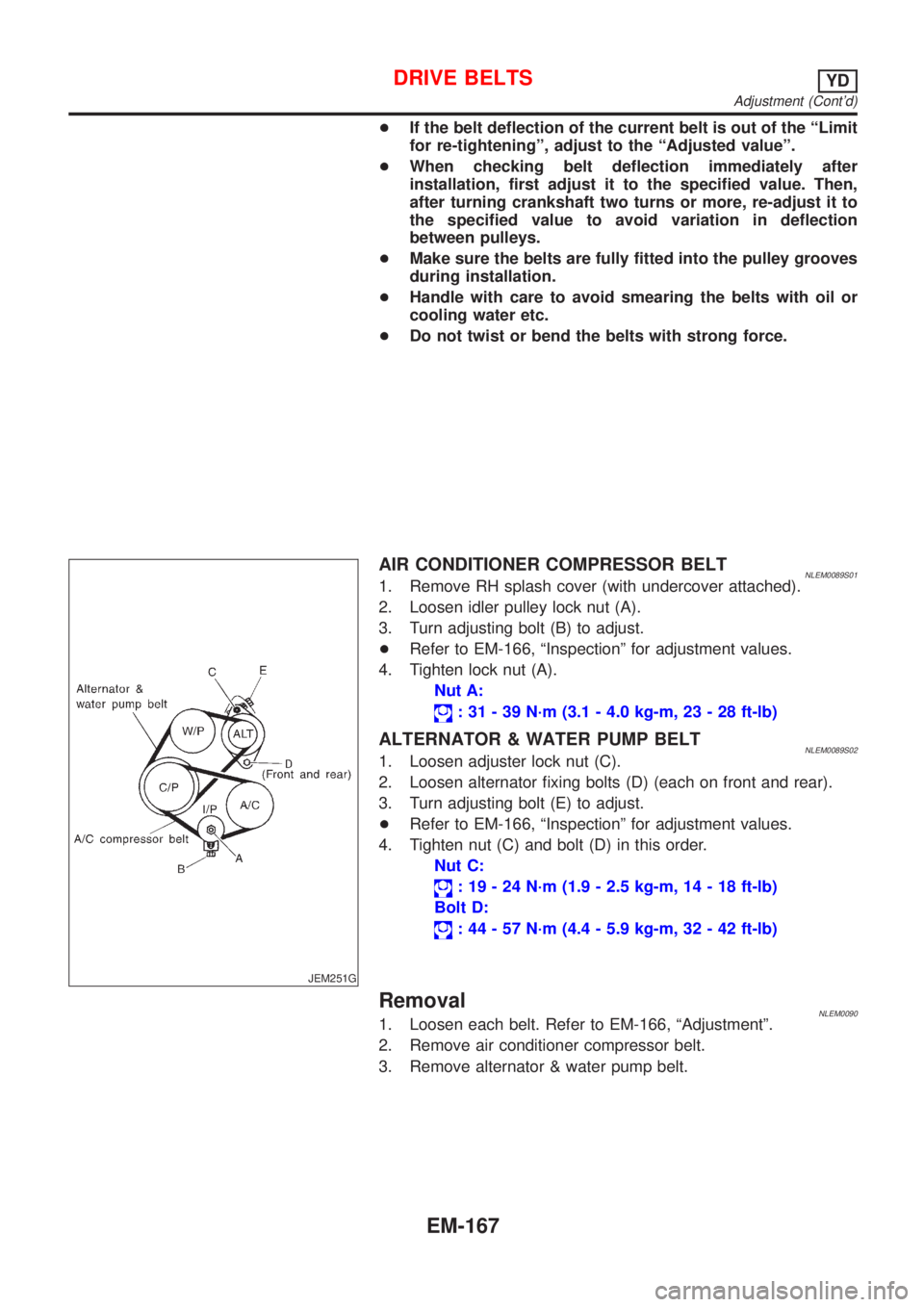
AIR CONDITIONER COMPRESSOR BELTNLEM0089S011. Remove RH splash cover (with undercover attached).
2. Loosen idler pulley lock nut (A).
3. Turn adjusting bolt (B) to adjust.
+Refer to EM-166, ªInspectionº for adjustment values.
4. Tighten lock nut (A).
Nut A:
: 31 - 39 N´m (3.1 - 4.0 kg-m, 23 - 28 ft-lb)
ALTERNATOR & WATER PUMP BELTNLEM0089S021. Loosen adjuster lock nut (C).
2. Loosen alternator fixing bolts (D) (each on front and rear).
3. Turn adjusting bolt (E) to adjust.
+Refer to EM-166, ªInspectionº for adjustment values.
4. Tighten nut (C) and bolt (D) in this order.
Nut C:
: 19 - 24 N´m (1.9 - 2.5 kg-m, 14 - 18 ft-lb)
Bolt D:
: 44 - 57 N´m (4.4 - 5.9 kg-m, 32 - 42 ft-lb)
RemovalNLEM00901. Loosen each belt. Refer to EM-166, ªAdjustmentº.
2. Remove air conditioner compressor belt.
3. Remove alternator & water pump belt.
DRIVE BELTSYD
Adjustment (Cont'd)
EM-167
Page 2476 of 3051
crankshaft position sensor (TDC sensor) from the assem-
bly.
+Always pay extra attention not to damage edge of crank-
shaft position sensor (TDC sensor) or ring gear teeth.
REMOVALNLEM0069S011. Remove engine undercover, and hood for hoisting.
2. Drain coolant from both cylinder block and radiator. Refer to
LC-59, ªChanging Engine Coolantº.
3. Remove the following parts:
+Battery
+RH and LH front wheels
+RH and LH splash covers (combined with undercover)
+Auxiliary belts
+Alternator
+Alternator brackets
+Radiator and cooling fan
+Engine cover
+Air ducts and air cleaner case
LH side of engine room:
4. Disconnect all harnesses and grounds that are connected to
components on vehicle.
5. Disconnect vacuum hose on vacuum pump side.
6. Disconnect fuel feed and fuel return hoses on engine side.
+Immediately put blind plugs into the openings to prevent
fuel from flowing out.
7. Disconnect heater hose. Plug opening of hose to prevent cool-
ant from flowing out.
RH side of engine room:
8. Remove air conditioner compressor from brackets and move
it toward vehicle side. Secure compressor on vehicle side with
rope.
Vehicle underside:
9. Remove exhaust front tube.
10. Disconnect two hoses from power steering pump and plug to
stop fluid.
11. Remove M/T control rod and support rod.
12. Remove ABS wheel sensor, and temporarily hang brake cali-
per with rope on vehicle side.
13. Remove RH and LH drive shafts.
SEM499G
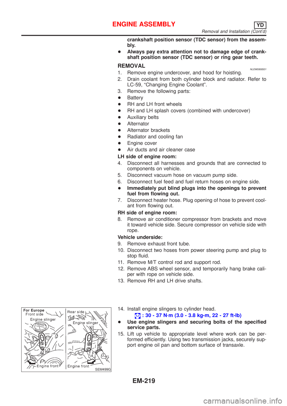
14. Install engine slingers to cylinder head.
: 30 - 37 N´m (3.0 - 3.8 kg-m, 22 - 27 ft-lb)
+Use engine slingers and securing bolts of the specified
service parts.
15. Lift up vehicle to appropriate level where work can be per-
formed efficiently. Using two transmission jacks, securely sup-
port engine oil pan and bottom surface of transaxle.
ENGINE ASSEMBLYYD
Removal and Installation (Cont'd)
EM-219
Page 2498 of 3051
General SpecificationsNLEM0075
Cylinder arrangementIn-line 4
Displacement cm
3(cu in)2,184 (133.27)
Bore and stroke mm (in)86 x 94 (3.39 x 3.70)
Valve arrangementDOHC
Firing order1-3-4-2
Number of piston ringsCompression 2
Oil 1
Number of main bearings5
Compression ratio18.0
Compression PressureNLEM0076Unit: kPa (bar, kg/cm2, psi)/200 rpm
Compression pressureStandard 3,138 (31.4, 32.0, 455)
Minimum 2,452 (24.5, 25.0, 356)
Differential limit between cylinders 490 (4.9, 5.0, 71)
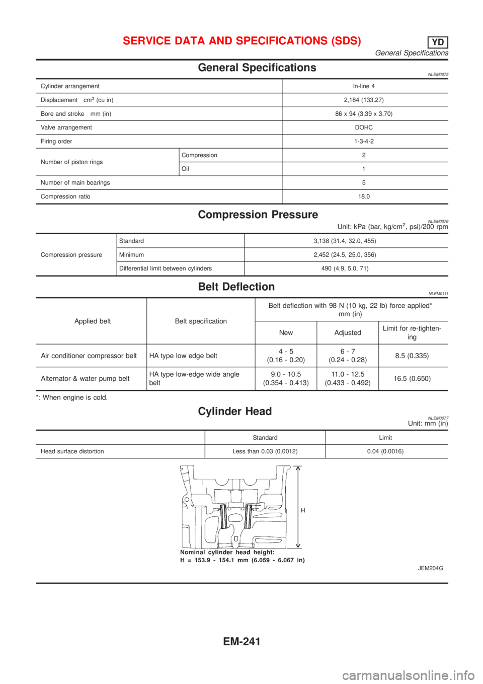
Belt DeflectionNLEM0111
Applied belt Belt specificationBelt deflection with 98 N (10 kg, 22 lb) force applied*
mm (in)
New AdjustedLimit for re-tighten-
ing
Air conditioner compressor belt HA type low edge belt4-5
(0.16 - 0.20)6-7
(0.24 - 0.28)8.5 (0.335)
Alternator & water pump beltHA type low-edge wide angle
belt9.0 - 10.5
(0.354 - 0.413)11.0 - 12.5
(0.433 - 0.492)16.5 (0.650)
*: When engine is cold.
Cylinder HeadNLEM0077Unit: mm (in)
Standard Limit
Head surface distortion Less than 0.03 (0.0012) 0.04 (0.0016)
JEM204G
SERVICE DATA AND SPECIFICATIONS (SDS)YD
General Specifications
EM-241
Page 2699 of 3051
Engine control component parts
location ................................ EC-26, 560, 1071
Engine control module (ECM) ........ EC-358, 880
Engine control system diagram and
chart .................................... EC-32, 566, 1076
Engine coolant temperature sensor
(ECTS) .............................. EC-169, 694, 1150
Engine fail-safe system .................. EC-123, 647
Engine oil precautions .................................. GI-7
Engine outer component parts ........... EM-12, 82
Engine removal ........................ EM-49, 130, 218
Engine room - See Engine
compartment .......................................... BT-66
Engine serial number ................................. GI-39
Evaporative emission (EVAP)
system ........................................... EC-39, 573
Exhaust gas recirculation (EGR)
valve ........... EC-310, 393, 446, 834, 921, 975
Exhaust system ................................... FE-11, 23
Exterior ...................................................... BT-38
F
F/PUMP - Wiring diagram ............. EC-518, 1034
FR02 - Wiring diagram .. EC-187, 207, 216, 415,
712, 732, 741, 945
FR02/H - Wiring diagram ............... EC-223, 422,
748, 952
FUEL - Wiring diagram ... EC-271, 279, 794, 802
Fan switch ................................................. HA-61
Final drive (FF M/T) ...................... MT-47, 63, 77
Finisher, interior - See Trim ....................... BT-28
Finisher, trunk lid ....................................... BT-31
Floor trim ................................................... BT-28
Fluids ........................................................ MA-20
Flywheel (clutch) ....................................... CL-22
Flywheel runout ........................ EM-60, 142, 235
Fog lamp, front, removal and
installation ................................................ BT-7
Fog lamp, front .......................................... EL-95
Fork rod (M/T) ..................................... MT-26, 64
Freeze frame data .............. EC-61, 71, 585, 596
Front axle .................................................... AX-2
Front bumper ............................................... BT-7
Front combination lamp removal and
installation ................................................ BT-7
Front disc brake ........................................ BR-24
Front door .................................................. BT-13
Front fog lamp removal and
installation ................................................ BT-7
Front fog lamp ........................................... EL-95
Front heated oxygen sensor (HO2S)
heater .......................... EC-221, 421, 746, 951
Front heated oxygen sensor (HO2S) ..... EC-184,
192, 198, 204, 214, 414, 709,
717, 723, 729, 739, 944Front seat belt ............................................. RS-5
Front seat .................................................. BT-46
Front suspension ........................................ SU-2
Front washer ............................................ EL-176
Front wiper ............................................... EL-176
Fuel cut control (at no load & high
engine speed) ..................... EC-39, 573, 1081
Fuel gauge ............................................... EL-130
Fuel injection system ............. EC-269, 277, 792,
800, 1079
Fuel injector .................................. EC-494, 1021
Fuel precautions ........................................... GI-8
Fuel pressure check ......................... EC-43, 577
Fuel pressure regulator .................... EC-44, 578
Fuel pressure release ....................... EC-43, 577
Fuel pump relay ............................ EC-516, 1032
Fuel pump ..................................... EC-516, 1032
Fuel system ........................................... FE-5, 15
Fuel tank vacuum relief valve ........... EC-40, 574
Fuse block ............................................... EL-527
Fuse ........................................................... EL-32
Fusible link ................................................. EL-32G
GLOW - Wiring diagram ....................... EC-1267
Garage jack and safety stand .................... GI-43
Gauges .................................................... EL-130
Gear components (M/T) ..................... MT-25, 63
Generator - See Alternator ....................... SC-28
Generic scan tool (GST) ................... EC-93, 617
Glass .......................................................... BT-14
Glow plug .............................................. EC-1267
Glow relay ............................................. EC-1267
Grease ...................................................... MA-20
Ground distribution .............................. EL-33, 48
H
H/LAMP - Wiring diagram .......................... EL-69
HEATER - Wiring diagram ........................ HA-23
HFC134a (R134a) system
precaution ................................................ HA-2
HFC134a (R134a) system service
procedure .............................................. HA-85
HFC134a (R134a) system service
tools ....................................................... HA-10
HFC134a system service equipment
precaution ................................................ HA-6
HORN - Wiring diagram .......................... EL-193
HSEAT - Wiring diagram ......................... EL-234
Harness connector ...................................... EL-5
Harness layout ......................................... EL-452
Hazard warning lamp .............................. EL-101
Headlamp removal and installation ............. BT-7
Headlamp washer .................................... EL-190
ALPHABETICAL INDEX
IDX-4
Page 2962 of 3051
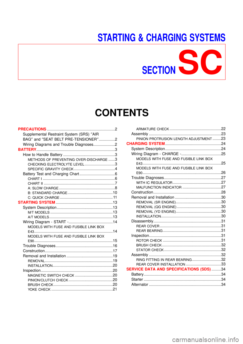
STARTING & CHARGING SYSTEMS
SECTION
SC
CONTENTS
PRECAUTIONS...............................................................2
Supplemental Restraint System (SRS)″AIR
BAG″and″SEAT BELT PRE-TENSIONER″...............2
Wiring Diagrams and Trouble Diagnoses....................2
BATTERY.........................................................................3
How to Handle Battery ................................................3
METHODS OF PREVENTING OVER-DISCHARGE......3
CHECKING ELECTROLYTE LEVEL............................3
SPECIFIC GRAVITY CHECK......................................4
Battery Test and Charging Chart .................................6
CHART I...................................................................6
CHART II..................................................................7
A: SLOW CHARGE....................................................8
B: STANDARD CHARGE..........................................10
C: QUICK CHARGE................................................. 11
STARTING SYSTEM.....................................................13
System Description ....................................................13
M/T MODELS..........................................................13
A/T MODELS...........................................................13
Wiring Diagram - START -.........................................14
MODELS WITH FUSE AND FUSIBLE LINK BOX
E43
.........................................................................14
MODELS WITH FUSE AND FUSIBLE LINK BOX
E90
.........................................................................15
Trouble Diagnoses.....................................................16
Construction ...............................................................17
Removal and Installation ...........................................19
REMOVAL...............................................................19
INSTALLATION........................................................20
Inspection...................................................................20
MAGNETIC SWITCH CHECK...................................20
PINION/CLUTCH CHECK.........................................20
BRUSH CHECK.......................................................20
YOKE CHECK.........................................................21
ARMATURE CHECK................................................22
Assembly ...................................................................23
PINION PROTRUSION LENGTH ADJUSTMENT........23
CHARGING SYSTEM....................................................24
System Description ....................................................24
Wiring Diagram - CHARGE -.....................................25
MODELS WITH FUSE AND FUSIBLE LINK BOX
E43
.........................................................................25
MODELS WITH FUSE AND FUSIBLE LINK BOX
E90
.........................................................................26
Trouble Diagnoses.....................................................27
WITH IC REGULATOR.............................................27
MALFUNCTION INDICATOR....................................27
Construction ...............................................................28
Removal and Installation ...........................................30
REMOVAL (SR ENGINE)..........................................30
REMOVAL (QG ENGINE).........................................30
REMOVAL (YD ENGINE)..........................................30
INSTALLATION........................................................30
Disassembly...............................................................31
REAR COVER.........................................................31
REAR BEARING......................................................31
Inspection...................................................................31
ROTOR CHECK......................................................31
BRUSH CHECK.......................................................32
STATOR CHECK.....................................................32
Assembly ...................................................................32
RING FITTING IN REAR BEARING...........................32
REAR COVER INSTALLATION.................................33
SERVICE DATA AND SPECIFICATIONS (SDS).........34
Battery........................................................................34
Starter ........................................................................34
Alternator ...................................................................34
Page 2991 of 3051

NEL732
Removal and InstallationNLSC0013REMOVAL (SR ENGINE)NLSC0013S041. Disconnect alternator connector, the terminal and A/C com-
pressor.
2. Loosen alternator upper (lock) bolt and the adjusting bolt.
3. Remove engine under cover RH.
4. Remove A/C compressor bolts×4.
5. Remove alternator mounting bracket bolt×1 and the nuts×2.
6. Loosen alternator lower bolt (long bolt).
7. Remove alternator upper bolt.
8. Move alternator towerd vehicle front.
9. Remove alternator mounting bracket bolt×1.
10. Remove alternator with mounting bracket.
MEL145L
REMOVAL (QG ENGINE)NLSC0013S011. Loosen drive belt idler pulley.
2. Remove drive belt idler pulley (include tightening screw).
3. Remove alternator harness.
4. Remove alternator upper bolt and lower bolt.
5. Remove alternator.
NEL645
REMOVAL (YD ENGINE)NLSC0013S031. Remove alternator harness.
2. Loosen alternator upper nut and lower bolt.
3. Loosen drive belt.
4. Remove alternator bracket bolts (two).
5. Remove alternator upper nut and lower bolt.
6. Remove alternator.
INSTALLATIONNLSC0013S02To install, reverse the removal procedure.
CHARGING SYSTEM
Removal and Installation
SC-30