2001 NISSAN ALMERA TINO sat nav
[x] Cancel search: sat navPage 1939 of 3051
System Description=NLEL0497Refer to Owner's Manual for audio system operating instructions.
Power is supplied at all times
+through 15A fuse
+to audio unit terminal 9
+to CD auto changer terminal 32.
With the ignition switch in the ACC or ON position, power is supplied
+through 10A fuse [No. 1, located in the fuse block (J/B)]
+to audio unit terminal 3,
+to CD auto changer terminal 36 and
Ground is supplied through the case of the audio unit.
Audio signals are supplied
+through audio unit terminals 7, 10, 11, 12, 13, 14, 15, 16
+to terminals 1 and 2 of front door speaker LH and RH,
+to terminals 1 and 2 of rear door speaker LH and RH and
+to terminals 1 and 2 of pillar tweeter LH and RH (with 6 speakers)
When the navigation system is triggered,
power is supplied
+through navi control unit terminal 46
+to speaker relay terminal 2
Ground is supplied
+through navi control unit terminal 44
+to speaker relay terminal 1
With power and ground supplied, the relay is energized, and then audio signal is interrupted to front door
speaker RH (LHD models) or LH (RHD models), and pillar tweeter RH (LHD models) or LH (RHD models)
For detailed, refer to ªNAVIGATION SYSTEMº.
NATS AUDIO LINKNLEL0497S01DescriptionNLEL0497S0101The link with the NATS IMMU implies that the audio unit can basically only be operated if connected to the
matching NATS IMMU to which the audio unit was initially fitted on the production line.
Since radio operation is impossible after the link with the NATS is disrupted theft of the audio unit is basically
useless since special equipment is required to reset the audio unit.
Initialization process for audio units that are linked to the NATS IMMU
New audio units will be delivered to the factories in the ªNEWº state, i.e. ready to be linked with the vehicle's
NATS. When the audio unit in ªNEWº state is first switched on at the factory, it will start up communication
with the vehicle's immobiliser control unit (IMMU) and send a code (the ªaudio unit Codeº) to the IMMU. The
IMMU will then store this code, which is unique to each audio unit, in its (permanent) memory.
Upon receipt of the code by the IMMU, the NATS will confirm correct receipt of the audio unit code to the audio
unit. Hereafter, the audio unit will operate as normal.
During the initialisation process, ªNEWº is displayed on the audio unit display. Normally though, communica-
tion between audio unit and IMMU takes such a short time (300 ms) that the audio unit seems to switch on
directly without showing ªNEWº on its display.
Normal operation
Each time the audio unit is switched on afterwards, the audio unit code will be verified between the audio unit
and the NATS before the audio unit becomes operational. During the code verification process, ªWAITº is
shown on the audio unit display. Again, the communication takes such a short time (300 ms) that the audio
unit seems to switch on directly without showing ªWAITº on its display.
When the radio is locked
In case of a audio unit being linked with the vehicle's NATS (immobilizer system), disconnection of the link
between the audio unit and the IMMU will cause the audio unit to switch into the lock (ªSECUREº) mode in
which the audio unit is fully inoperative. Hence, repair of the audio unit is basically impossible, unless the audio
unit is reset to the ªNEWº state for which special decoding equipment is required.
Clarion has provided their authorized service representatives with so called ªdecoder boxesº which can bring
the audio unit back to the ªNEWº state, enabling the audio unit to be switched on after which repair can be
AUDIO
System Description
EL-208
Page 2101 of 3051
PrecautionsNLEL0510WARNING:
Do not attempt to disassemble the monitor. Parts of the monitor have high voltages that can result in
severe and dangerous electric shock.
CAUTION:
+Do not reverse battery connections.
+Do not attach unauthorized parts.
+Protect the unit from severe impact.
NOTE:
Before beginning repair, determine whether or not the unit is defective. Refer to ªThis Condition Is Not
Abnormalº (EL-432).
Component Parts LocationNLEL0511For details, refer to ªELECTRICAL UNIT LAYOUTº (EL-442) and ªHARNESS LAYOUTº (EL-452).
SEL504X
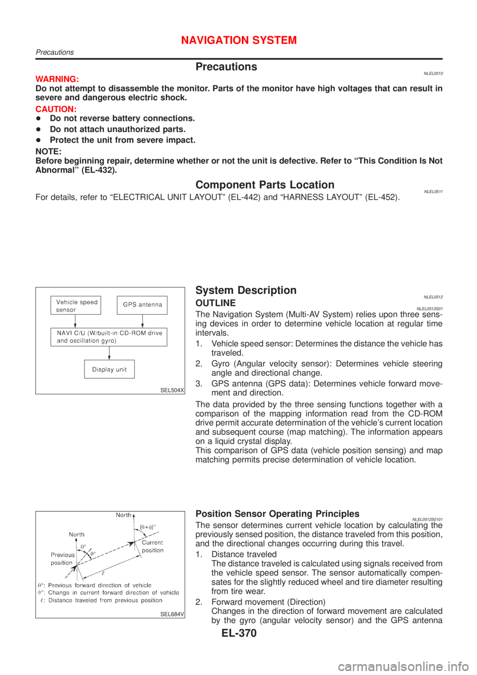
System DescriptionNLEL0512OUTLINENLEL0512S01The Navigation System (Multi-AV System) relies upon three sens-
ing devices in order to determine vehicle location at regular time
intervals.
1. Vehicle speed sensor: Determines the distance the vehicle has
traveled.
2. Gyro (Angular velocity sensor): Determines vehicle steering
angle and directional change.
3. GPS antenna (GPS data): Determines vehicle forward move-
ment and direction.
The data provided by the three sensing functions together with a
comparison of the mapping information read from the CD-ROM
drive permit accurate determination of the vehicle's current location
and subsequent course (map matching). The information appears
on a liquid crystal display.
This comparison of GPS data (vehicle position sensing) and map
matching permits precise determination of vehicle location.
SEL684V
Position Sensor Operating PrinciplesNLEL0512S0101The sensor determines current vehicle location by calculating the
previously sensed position, the distance traveled from this position,
and the directional changes occurring during this travel.
1. Distance traveled
The distance traveled is calculated using signals received from
the vehicle speed sensor. The sensor automatically compen-
sates for the slightly reduced wheel and tire diameter resulting
from tire wear.
2. Forward movement (Direction)
Changes in the direction of forward movement are calculated
by the gyro (angular velocity sensor) and the GPS antenna
NAVIGATION SYSTEM
Precautions
EL-370
Page 2103 of 3051
SEL526V
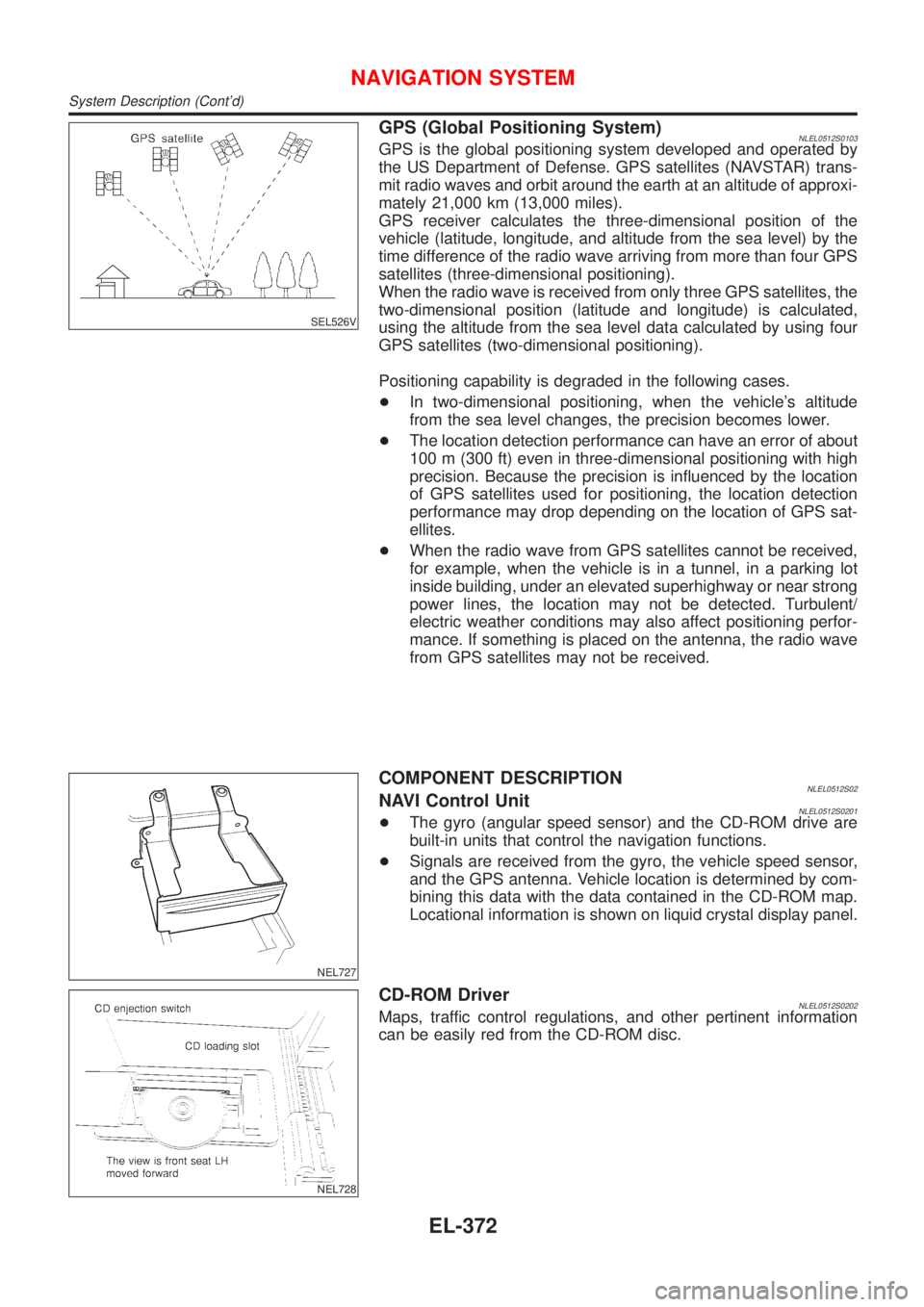
GPS (Global Positioning System)NLEL0512S0103GPS is the global positioning system developed and operated by
the US Department of Defense. GPS satellites (NAVSTAR) trans-
mit radio waves and orbit around the earth at an altitude of approxi-
mately 21,000 km (13,000 miles).
GPS receiver calculates the three-dimensional position of the
vehicle (latitude, longitude, and altitude from the sea level) by the
time difference of the radio wave arriving from more than four GPS
satellites (three-dimensional positioning).
When the radio wave is received from only three GPS satellites, the
two-dimensional position (latitude and longitude) is calculated,
using the altitude from the sea level data calculated by using four
GPS satellites (two-dimensional positioning).
Positioning capability is degraded in the following cases.
+In two-dimensional positioning, when the vehicle's altitude
from the sea level changes, the precision becomes lower.
+The location detection performance can have an error of about
100 m (300 ft) even in three-dimensional positioning with high
precision. Because the precision is influenced by the location
of GPS satellites used for positioning, the location detection
performance may drop depending on the location of GPS sat-
ellites.
+When the radio wave from GPS satellites cannot be received,
for example, when the vehicle is in a tunnel, in a parking lot
inside building, under an elevated superhighway or near strong
power lines, the location may not be detected. Turbulent/
electric weather conditions may also affect positioning perfor-
mance. If something is placed on the antenna, the radio wave
from GPS satellites may not be received.
NEL727
COMPONENT DESCRIPTIONNLEL0512S02NAVI Control UnitNLEL0512S0201+The gyro (angular speed sensor) and the CD-ROM drive are
built-in units that control the navigation functions.
+Signals are received from the gyro, the vehicle speed sensor,
and the GPS antenna. Vehicle location is determined by com-
bining this data with the data contained in the CD-ROM map.
Locational information is shown on liquid crystal display panel.
NEL728
CD-ROM DriverNLEL0512S0202Maps, traffic control regulations, and other pertinent information
can be easily red from the CD-ROM disc.
NAVIGATION SYSTEM
System Description (Cont'd)
EL-372
Page 2132 of 3051
Self-diagnosis ModeNLEL0515APPLICATION ITEMSNLEL0515S01
Mode DescriptionReference
page
Self DiagnosisSelf-diagnosis for Navigation, Display and GPS Antenna
connection.EL-402
Confirmation/
adjustmentDiagnose the DisplayColor and gray gradation of display can be checked in
this mode.EL-410
Diagnosis for Signals from the CarSeveral input signals to NAVI control unit, can be moni-
tored in this mode.EL-408
NavigationCheck the map CD-
ROM versionThe version (parts number) of inserted CD-ROM can be
checked in this model.EL-409
Error historyDiagnosis results previously stored in the memory
(before turning ignition switch ON) are displayed in this
mode. Time and location when/where the errors
occurred are also displayed.EL-404
Longitude & LatitudeDisplay the map. Use the joystick to adjust position. Lon-
gitude and latitude will be displayed.EL-411
Adjust the AngleTurning angle of the vehicle on the display can be
adjusted in this mode.EL-412
Speed CalibrationUnder ordinary conditions, the navigation system dis-
tance measuring function will automatically compensate
for minute decreases in wheel and tire diameter caused
by tire wear or low pressure. Speed calibration immedi-
ately restores system accuracy in cases such as when
distance calibration is needed because of the use of tire
chains in inclement weather.EL-413
Initialize LocationThis mode is for initializing the current location. Use
when the vehicle is transported a long distance by a
trailer, etc.EL-414
NEL729
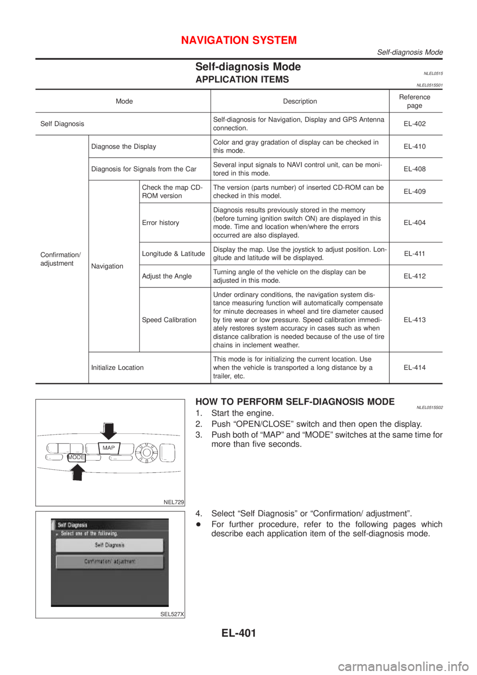
HOW TO PERFORM SELF-DIAGNOSIS MODENLEL0515S021. Start the engine.
2. Push ªOPEN/CLOSEº switch and then open the display.
3. Push both of ªMAPº and ªMODEº switches at the same time for
more than five seconds.
SEL527X
4. Select ªSelf Diagnosisº or ªConfirmation/ adjustmentº.
+For further procedure, refer to the following pages which
describe each application item of the self-diagnosis mode.
NAVIGATION SYSTEM
Self-diagnosis Mode
EL-401
Page 2145 of 3051
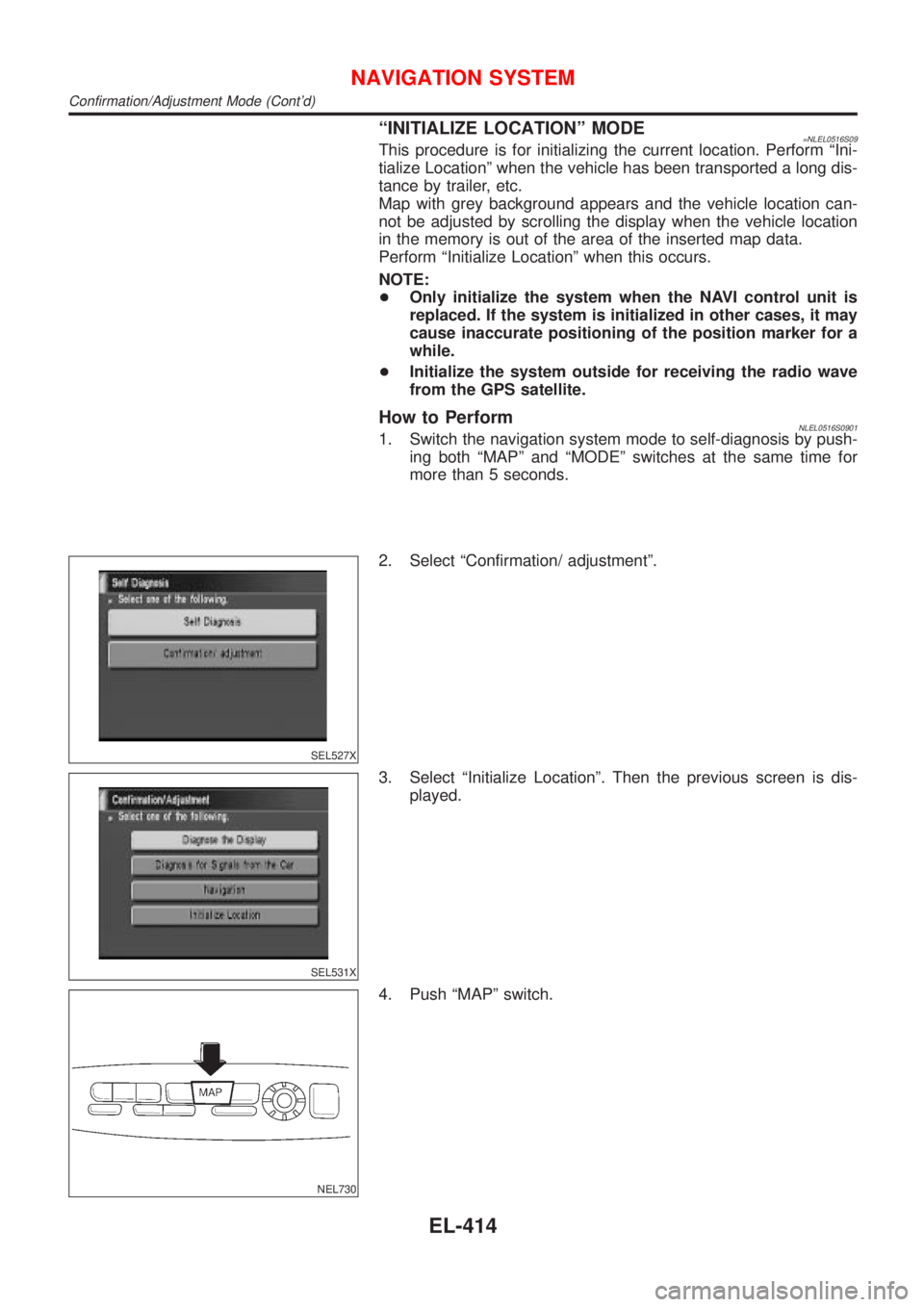
ªINITIALIZE LOCATIONº MODE=NLEL0516S09This procedure is for initializing the current location. Perform ªIni-
tialize Locationº when the vehicle has been transported a long dis-
tance by trailer, etc.
Map with grey background appears and the vehicle location can-
not be adjusted by scrolling the display when the vehicle location
in the memory is out of the area of the inserted map data.
Perform ªInitialize Locationº when this occurs.
NOTE:
+Only initialize the system when the NAVI control unit is
replaced. If the system is initialized in other cases, it may
cause inaccurate positioning of the position marker for a
while.
+Initialize the system outside for receiving the radio wave
from the GPS satellite.
How to PerformNLEL0516S09011. Switch the navigation system mode to self-diagnosis by push-
ing both ªMAPº and ªMODEº switches at the same time for
more than 5 seconds.
SEL527X
2. Select ªConfirmation/ adjustmentº.
SEL531X
3. Select ªInitialize Locationº. Then the previous screen is dis-
played.
NEL730
4. Push ªMAPº switch.
NAVIGATION SYSTEM
Confirmation/Adjustment Mode (Cont'd)
EL-414
Page 2146 of 3051
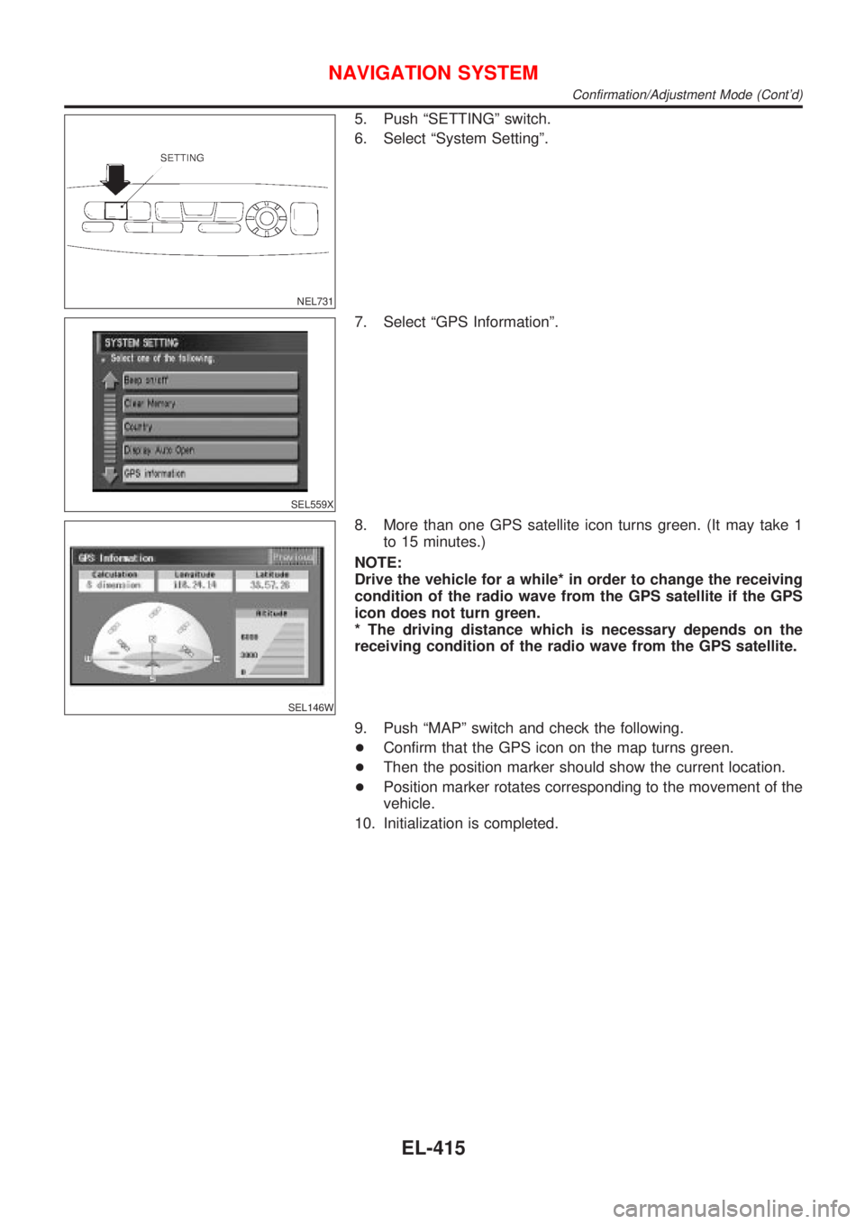
NEL731
5. Push ªSETTINGº switch.
6. Select ªSystem Settingº.
SEL559X
7. Select ªGPS Informationº.
SEL146W
8. More than one GPS satellite icon turns green. (It may take 1
to 15 minutes.)
NOTE:
Drive the vehicle for a while* in order to change the receiving
condition of the radio wave from the GPS satellite if the GPS
icon does not turn green.
* The driving distance which is necessary depends on the
receiving condition of the radio wave from the GPS satellite.
9. Push ªMAPº switch and check the following.
+Confirm that the GPS icon on the map turns green.
+Then the position marker should show the current location.
+Position marker rotates corresponding to the movement of the
vehicle.
10. Initialization is completed.
NAVIGATION SYSTEM
Confirmation/Adjustment Mode (Cont'd)
EL-415
Page 2147 of 3051
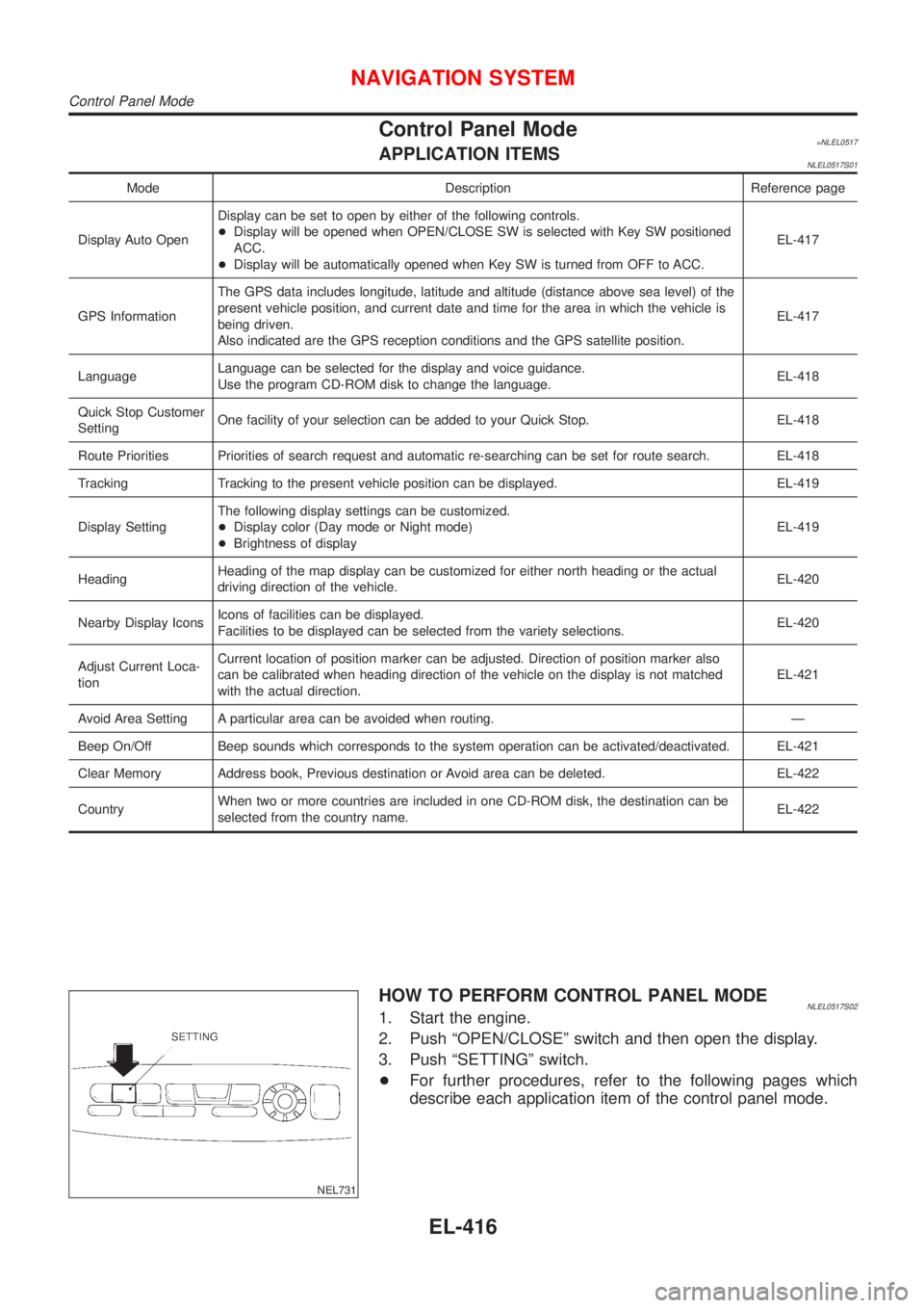
Control Panel Mode=NLEL0517APPLICATION ITEMSNLEL0517S01
Mode Description Reference page
Display Auto OpenDisplay can be set to open by either of the following controls.
+Display will be opened when OPEN/CLOSE SW is selected with Key SW positioned
ACC.
+Display will be automatically opened when Key SW is turned from OFF to ACC.EL-417
GPS InformationThe GPS data includes longitude, latitude and altitude (distance above sea level) of the
present vehicle position, and current date and time for the area in which the vehicle is
being driven.
Also indicated are the GPS reception conditions and the GPS satellite position.EL-417
LanguageLanguage can be selected for the display and voice guidance.
Use the program CD-ROM disk to change the language.EL-418
Quick Stop Customer
SettingOne facility of your selection can be added to your Quick Stop. EL-418
Route Priorities Priorities of search request and automatic re-searching can be set for route search. EL-418
Tracking Tracking to the present vehicle position can be displayed. EL-419
Display SettingThe following display settings can be customized.
+Display color (Day mode or Night mode)
+Brightness of displayEL-419
HeadingHeading of the map display can be customized for either north heading or the actual
driving direction of the vehicle.EL-420
Nearby Display IconsIcons of facilities can be displayed.
Facilities to be displayed can be selected from the variety selections.EL-420
Adjust Current Loca-
tionCurrent location of position marker can be adjusted. Direction of position marker also
can be calibrated when heading direction of the vehicle on the display is not matched
with the actual direction.EL-421
Avoid Area Setting A particular area can be avoided when routing. Ð
Beep On/Off Beep sounds which corresponds to the system operation can be activated/deactivated. EL-421
Clear Memory Address book, Previous destination or Avoid area can be deleted. EL-422
CountryWhen two or more countries are included in one CD-ROM disk, the destination can be
selected from the country name.EL-422
NEL731
HOW TO PERFORM CONTROL PANEL MODENLEL0517S021. Start the engine.
2. Push ªOPEN/CLOSEº switch and then open the display.
3. Push ªSETTINGº switch.
+For further procedures, refer to the following pages which
describe each application item of the control panel mode.
NAVIGATION SYSTEM
Control Panel Mode
EL-416
Page 2168 of 3051
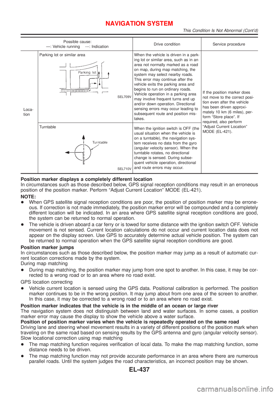
Possible cause:
Ð: Vehicle running ---: IndicationDrive condition Service procedure
Loca-
tionParking lot or similar area
SEL709V
When the vehicle is driven in a park-
ing lot or similar area, such as in an
area not normally marked as a road
on map, during map matching, the
system may select nearby roads.
This error may continue after the
vehicle exits the parking area and
begins to run on ordinary roads.
Vehicle operation in a parking area
may involve frequent turns and up
and/or down operation. Directional
sensing errors may occur leading to
subsequent route and position mis-
takes.If the position marker does
not move to the correct posi-
tion even after the vehicle
has been driven approxi-
mately 10 km (6 miles), per-
form ªStore placeº. If
required, also perform
ªAdjust Current Locationº
MODE (EL-421). Turntable
SEL710V
When the ignition switch is OFF (the
usual situation when the vehicle is
on a turntable), the navigation sys-
tem receives no data from the gyro
(angular velocity sensor). When the
turntable rotates, no directional
change is sensed. During subse-
quent vehicle operation, directional
and route errors may occur.
Position marker displays a completely different location
In circumstances such as those described below, GPS signal reception conditions may result in an erroneous
position of the position marker. Perform ªAdjust Current Locationº MODE (EL-421).
NOTE:
+When GPS satellite signal reception conditions are poor, the position of position marker may be errone-
ous. If correction is not made immediately, the position marker error will be compounded and a completely
different location will be indicated. In an area where GPS satellite signal reception conditions are good,
the system can be returned to normal operation.
+The vehicle is driven aboard a car ferry or is towed for some distance with the ignition switch OFF. Vehicle
movement is not sensed. Current location calculations do not occur and current location data does not
appear on the display screen. Use GPS to accurately determine actual vehicle position. The system can
be returned to normal operation when the GPS satellite signal reception conditions are good.
Position marker jumps
In circumstances such as those described below, the position marker may jump as a result of automatic cur-
rent location corrections made by the system.
During map matching
+During map matching, the position marker may jump from one spot to another. In this case, it may be cor-
rected to a wrong road or to an area where no road exist.
GPS location correcting
+Vehicle current location is sensed using the GPS data. Positional calibration is performed. The position
marker continues to be in the wrong position. It may jump about from one area of the screen to another.
In this case, it may be corrected to a wrong road or to an area where no road exist.
Position marker indicates that the vehicle is in the middle of an ocean or large river
The navigation system does not distinguish between land and water surfaces. In some cases, a position
marker error may cause the display to show the vehicle above a water surface.
Position of position marker varies when the vehicle is repeatedly operated on the same road
Driving lane and steering wheel movement results in a variety of different positions of the position mark when
traveling on the same road based on sensing results by the GPS antenna and gyro (angular velocity sensor).
Slow locational correction using map matching
+The map matching function requires verification of local data. To make the map matching function, some
distance needs to be driven.
+The map matching function may not provide accurate performance in an area where there are numerous
parallel roads. Until the system judges the road characteristics, an incorrect position may be shown.
NAVIGATION SYSTEM
This Condition Is Not Abnormal (Cont'd)
EL-437