2001 NISSAN ALMERA TINO length
[x] Cancel search: lengthPage 382 of 3051
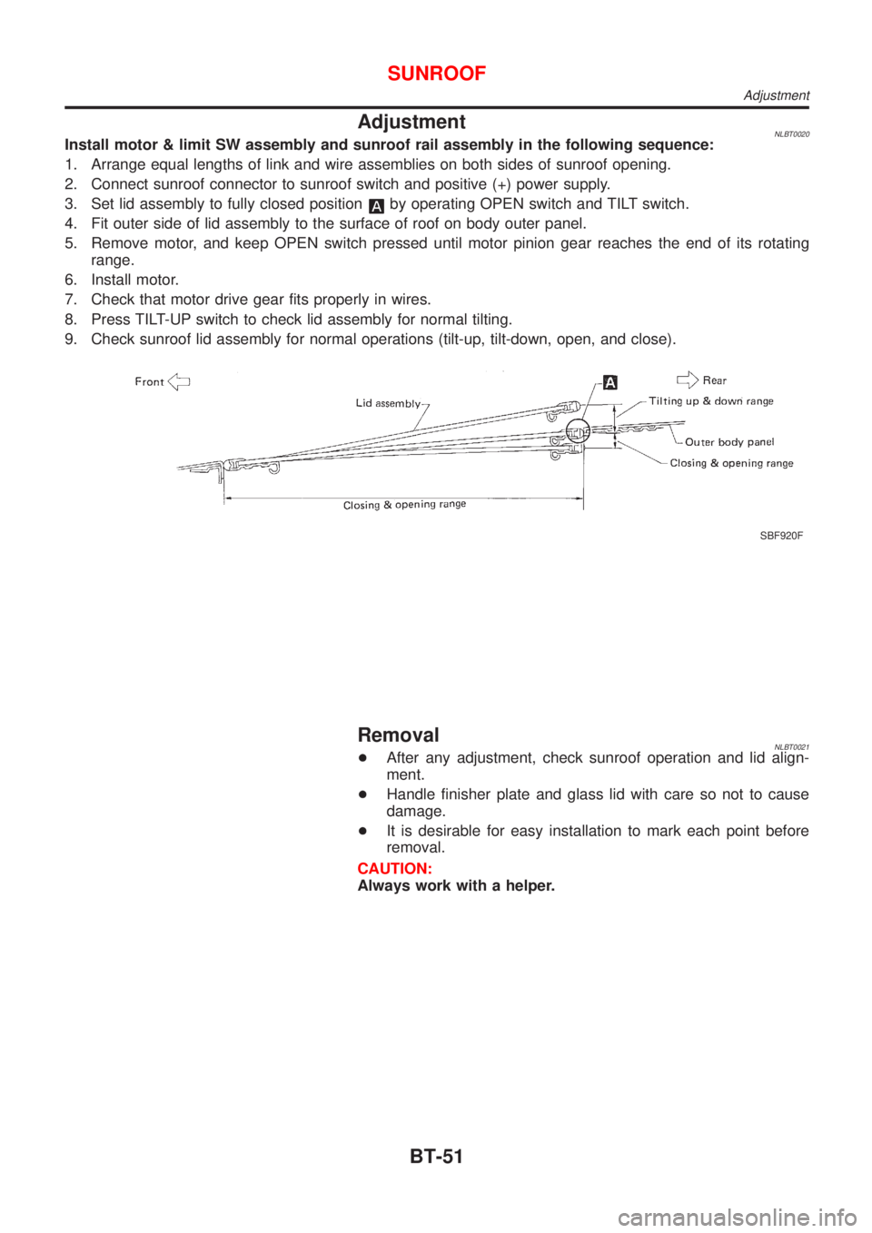
AdjustmentNLBT0020Install motor & limit SW assembly and sunroof rail assembly in the following sequence:
1. Arrange equal lengths of link and wire assemblies on both sides of sunroof opening.
2. Connect sunroof connector to sunroof switch and positive (+) power supply.
3. Set lid assembly to fully closed position
by operating OPEN switch and TILT switch.
4. Fit outer side of lid assembly to the surface of roof on body outer panel.
5. Remove motor, and keep OPEN switch pressed until motor pinion gear reaches the end of its rotating
range.
6. Install motor.
7. Check that motor drive gear fits properly in wires.
8. Press TILT-UP switch to check lid assembly for normal tilting.
9. Check sunroof lid assembly for normal operations (tilt-up, tilt-down, open, and close).
SBF920F
RemovalNLBT0021+After any adjustment, check sunroof operation and lid align-
ment.
+Handle finisher plate and glass lid with care so not to cause
damage.
+It is desirable for easy installation to mark each point before
removal.
CAUTION:
Always work with a helper.
SUNROOF
Adjustment
BT-51
Page 396 of 3051
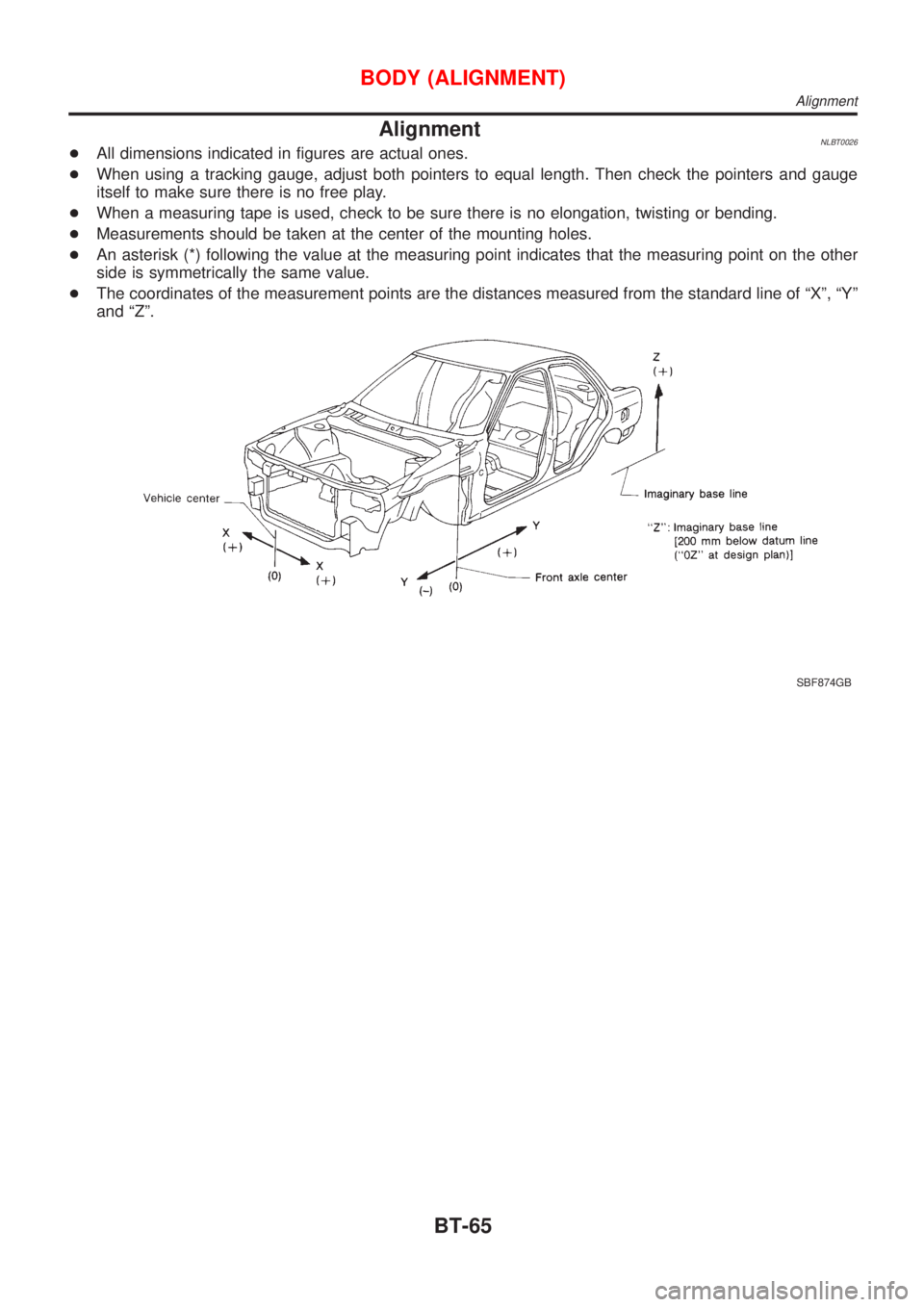
AlignmentNLBT0026+All dimensions indicated in figures are actual ones.
+When using a tracking gauge, adjust both pointers to equal length. Then check the pointers and gauge
itself to make sure there is no free play.
+When a measuring tape is used, check to be sure there is no elongation, twisting or bending.
+Measurements should be taken at the center of the mounting holes.
+An asterisk (*) following the value at the measuring point indicates that the measuring point on the other
side is symmetrically the same value.
+The coordinates of the measurement points are the distances measured from the standard line of ªXº, ªYº
and ªZº.
SBF874GB
BODY (ALIGNMENT)
Alignment
BT-65
Page 460 of 3051
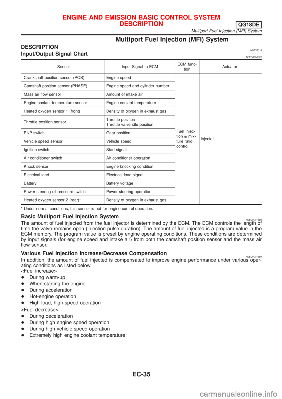
Multiport Fuel Injection (MFI) System
DESCRIPTIONNLEC0014Input/Output Signal ChartNLEC0014S01
Sensor Input Signal to ECMECM func-
tionActuator
Crankshaft position sensor (POS) Engine speed
Fuel injec-
tion & mix-
ture ratio
controlInjector Camshaft position sensor (PHASE) Engine speed and cylinder number
Mass air flow sensor Amount of intake air
Engine coolant temperature sensor Engine coolant temperature
Heated oxygen sensor 1 (front) Density of oxygen in exhaust gas
Throttle position sensorThrottle position
Throttle valve idle position
PNP switch Gear position
Vehicle speed sensor Vehicle speed
Ignition switch Start signal
Air conditioner switch Air conditioner operation
Knock sensor Engine knocking condition
Electrical load Electrical load signal
Battery Battery voltage
Power steering oil pressure switch Power steering operation
Heated oxygen sensor 2 (rear)* Density of oxygen in exhaust gas
* Under normal conditions, this sensor is not for engine control operation.
Basic Multiport Fuel Injection SystemNLEC0014S02The amount of fuel injected from the fuel injector is determined by the ECM. The ECM controls the length of
time the valve remains open (injection pulse duration). The amount of fuel injected is a program value in the
ECM memory. The program value is preset by engine operating conditions. These conditions are determined
by input signals (for engine speed and intake air) from both the camshaft position sensor and the mass air
flow sensor.
Various Fuel Injection Increase/Decrease CompensationNLEC0014S03In addition, the amount of fuel injected is compensated to improve engine performance under various oper-
ating conditions as listed below.
+During warm-up
+When starting the engine
+During acceleration
+Hot-engine operation
+High-load, high-speed operation
+During deceleration
+During high engine speed operation
+During high vehicle speed operation
+Extremely high engine coolant temperature
ENGINE AND EMISSION BASIC CONTROL SYSTEM
DESCRIPTION
QG18DE
Multiport Fuel Injection (MFI) System
EC-35
Page 919 of 3051
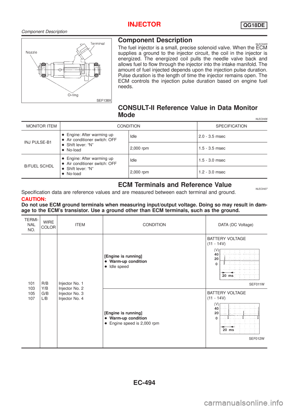
SEF138X
Component DescriptionNLEC0435The fuel injector is a small, precise solenoid valve. When the ECM
supplies a ground to the injector circuit, the coil in the injector is
energized. The energized coil pulls the needle valve back and
allows fuel to flow through the injector into the intake manifold. The
amount of fuel injected depends upon the injection pulse duration.
Pulse duration is the length of time the injector remains open. The
ECM controls the injection pulse duration based on engine fuel
needs.
CONSULT-II Reference Value in Data Monitor
Mode
NLEC0436
MONITOR ITEM CONDITION SPECIFICATION
INJ PULSE-B1+Engine: After warming up
+Air conditioner switch: OFF
+Shift lever: ªNº
+No-loadIdle 2.0 - 3.5 msec
2,000 rpm 1.5 - 3.5 msec
B/FUEL SCHDL+Engine: After warming up
+Air conditioner switch: OFF
+Shift lever: ªNº
+No-loadIdle 1.5 - 3.0 msec
2,000 rpm 1.2 - 3.0 msec
ECM Terminals and Reference ValueNLEC0437Specification data are reference values and are measured between each terminal and ground.
CAUTION:
Do not use ECM ground terminals when measuring input/output voltage. Doing so may result in dam-
age to the ECM's transistor. Use a ground other than ECM terminals, such as the ground.
TERMI-
NAL
NO.WIRE
COLORITEM CONDITION DATA (DC Voltage)
101
103
105
107R/B
Y/B
G/B
L/BInjector No. 1
Injector No. 2
Injector No. 3
Injector No. 4[Engine is running]
+Warm-up condition
+Idle speedBATTERY VOLTAGE
(11 - 14V)
SEF011W
[Engine is running]
+Warm-up condition
+Engine speed is 2,000 rpmBATTERY VOLTAGE
(11 - 14V)
SEF012W
INJECTORQG18DE
Component Description
EC-494
Page 994 of 3051
Multiport Fuel Injection (MFI) System
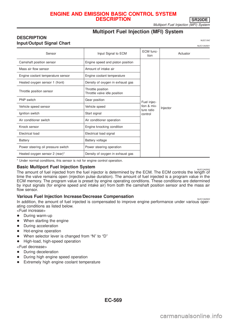
DESCRIPTIONNLEC1342Input/Output Signal ChartNLEC1342S01
Sensor Input Signal to ECMECM func-
tionActuator
Camshaft position sensor Engine speed and piston position
Fuel injec-
tion & mix-
ture ratio
controlInjector Mass air flow sensor Amount of intake air
Engine coolant temperature sensor Engine coolant temperature
Heated oxygen sensor 1 (front) Density of oxygen in exhaust gas
Throttle position sensorThrottle position
Throttle valve idle position
PNP switch Gear position
Vehicle speed sensor Vehicle speed
Ignition switch Start signal
Air conditioner switch Air conditioner operation
Knock sensor Engine knocking condition
Electrical load Electrical load signal
Battery Battery voltage
Power steering oil pressure switch Power steering operation
Heated oxygen sensor 2 (rear)* Density of oxygen in exhaust gas
* Under normal conditions, this sensor is not for engine control operation.
Basic Multiport Fuel Injection SystemNLEC1342S02The amount of fuel injected from the fuel injector is determined by the ECM. The ECM controls the length of
time the valve remains open (injection pulse duration). The amount of fuel injected is a program value in the
ECM memory. The program value is preset by engine operating conditions. These conditions are determined
by input signals (for engine speed and intake air) from both the camshaft position sensor and the mass air
flow sensor.
Various Fuel Injection Increase/Decrease CompensationNLEC1342S03In addition, the amount of fuel injected is compensated to improve engine performance under various oper-
ating conditions as listed below.
+During warm-up
+When starting the engine
+During acceleration
+Hot-engine operation
+When selector lever is changed from ªNº to ªDº
+High-load, high-speed operation
+During deceleration
+During high engine speed operation
+Extremely high engine coolant temperature
ENGINE AND EMISSION BASIC CONTROL SYSTEM
DESCRIPTION
SR20DE
Multiport Fuel Injection (MFI) System
EC-569
Page 1446 of 3051
SEF138X
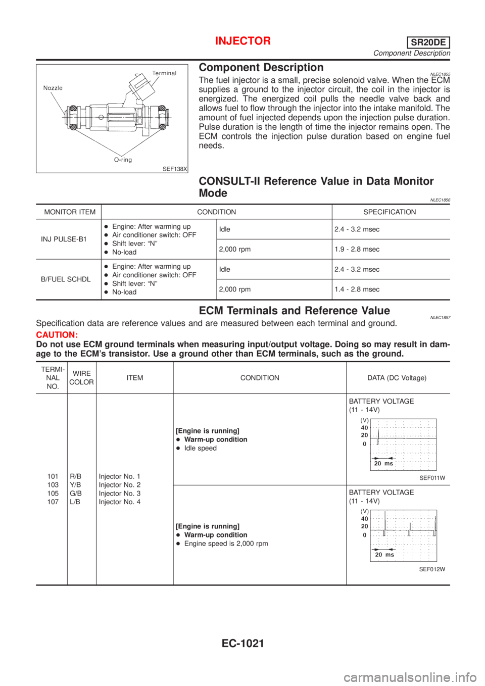
Component DescriptionNLEC1855The fuel injector is a small, precise solenoid valve. When the ECM
supplies a ground to the injector circuit, the coil in the injector is
energized. The energized coil pulls the needle valve back and
allows fuel to flow through the injector into the intake manifold. The
amount of fuel injected depends upon the injection pulse duration.
Pulse duration is the length of time the injector remains open. The
ECM controls the injection pulse duration based on engine fuel
needs.
CONSULT-II Reference Value in Data Monitor
Mode
NLEC1856
MONITOR ITEM CONDITION SPECIFICATION
INJ PULSE-B1+Engine: After warming up
+Air conditioner switch: OFF
+Shift lever: ªNº
+No-loadIdle 2.4 - 3.2 msec
2,000 rpm 1.9 - 2.8 msec
B/FUEL SCHDL+Engine: After warming up
+Air conditioner switch: OFF
+Shift lever: ªNº
+No-loadIdle 2.4 - 3.2 msec
2,000 rpm 1.4 - 2.8 msec
ECM Terminals and Reference ValueNLEC1857Specification data are reference values and are measured between each terminal and ground.
CAUTION:
Do not use ECM ground terminals when measuring input/output voltage. Doing so may result in dam-
age to the ECM's transistor. Use a ground other than ECM terminals, such as the ground.
TERMI-
NAL
NO.WIRE
COLORITEM CONDITION DATA (DC Voltage)
101
103
105
107R/B
Y/B
G/B
L/BInjector No. 1
Injector No. 2
Injector No. 3
Injector No. 4[Engine is running]
+Warm-up condition
+Idle speedBATTERY VOLTAGE
(11 - 14V)
SEF011W
[Engine is running]
+Warm-up condition
+Engine speed is 2,000 rpmBATTERY VOLTAGE
(11 - 14V)
SEF012W
INJECTORSR20DE
Component Description
EC-1021
Page 1515 of 3051
JEF360Y
JEF361Y
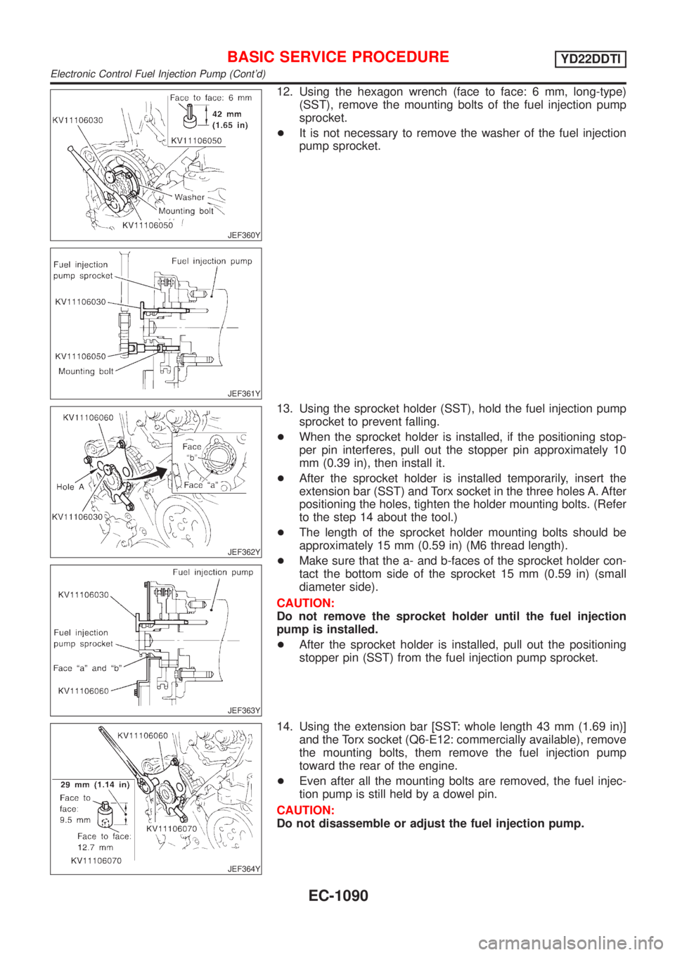
12. Using the hexagon wrench (face to face: 6 mm, long-type)
(SST), remove the mounting bolts of the fuel injection pump
sprocket.
+It is not necessary to remove the washer of the fuel injection
pump sprocket.
JEF362Y
JEF363Y
13. Using the sprocket holder (SST), hold the fuel injection pump
sprocket to prevent falling.
+When the sprocket holder is installed, if the positioning stop-
per pin interferes, pull out the stopper pin approximately 10
mm (0.39 in), then install it.
+After the sprocket holder is installed temporarily, insert the
extension bar (SST) and Torx socket in the three holes A. After
positioning the holes, tighten the holder mounting bolts. (Refer
to the step 14 about the tool.)
+The length of the sprocket holder mounting bolts should be
approximately 15 mm (0.59 in) (M6 thread length).
+Make sure that the a- and b-faces of the sprocket holder con-
tact the bottom side of the sprocket 15 mm (0.59 in) (small
diameter side).
CAUTION:
Do not remove the sprocket holder until the fuel injection
pump is installed.
+After the sprocket holder is installed, pull out the positioning
stopper pin (SST) from the fuel injection pump sprocket.
JEF364Y
14. Using the extension bar [SST: whole length 43 mm (1.69 in)]
and the Torx socket (Q6-E12: commercially available), remove
the mounting bolts, them remove the fuel injection pump
toward the rear of the engine.
+Even after all the mounting bolts are removed, the fuel injec-
tion pump is still held by a dowel pin.
CAUTION:
Do not disassemble or adjust the fuel injection pump.
BASIC SERVICE PROCEDUREYD22DDTI
Electronic Control Fuel Injection Pump (Cont'd)
EC-1090
Page 2312 of 3051
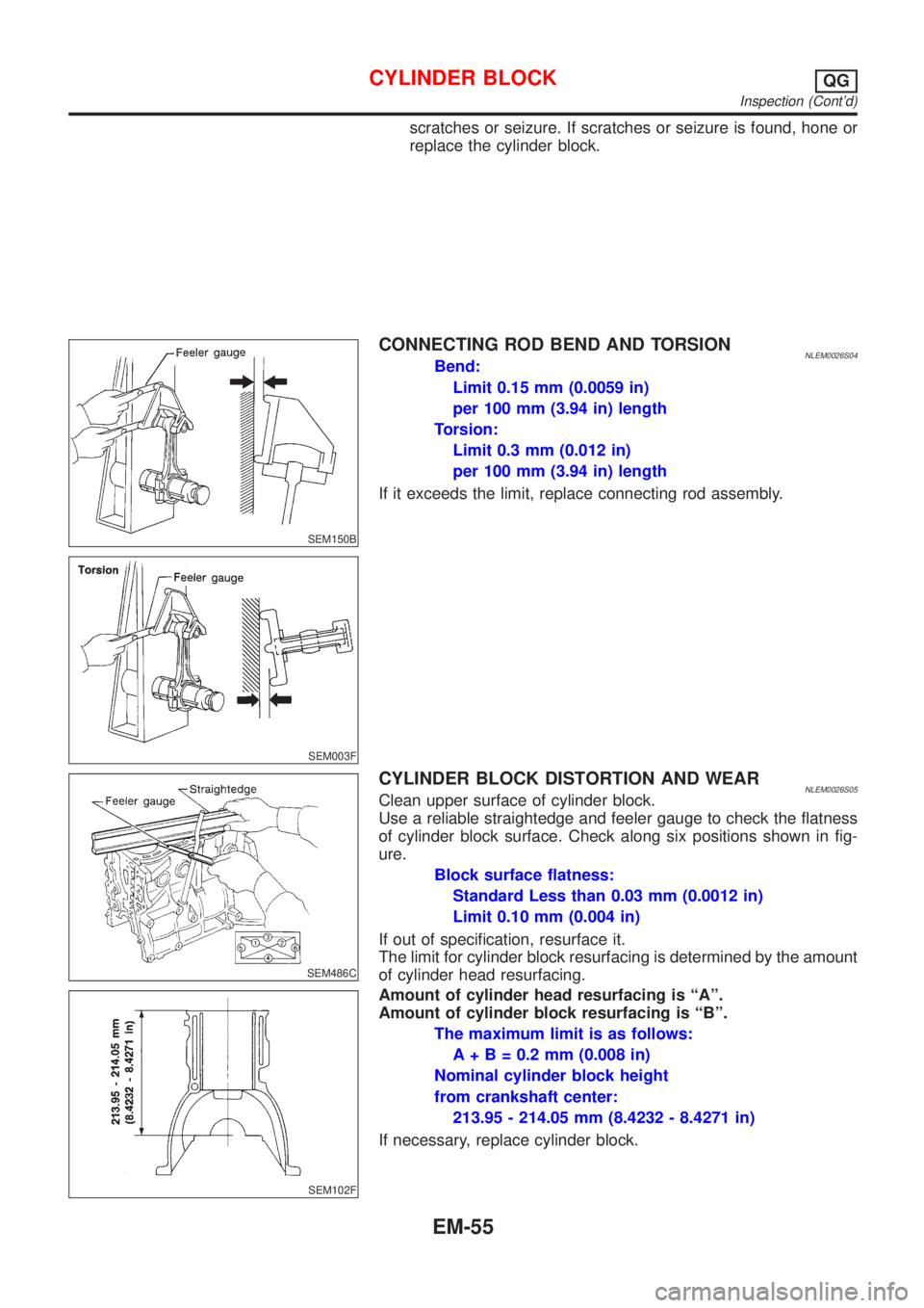
scratches or seizure. If scratches or seizure is found, hone or
replace the cylinder block.
SEM150B
CONNECTING ROD BEND AND TORSIONNLEM0026S04Bend:
Limit 0.15 mm (0.0059 in)
per 100 mm (3.94 in) length
Torsion:
Limit 0.3 mm (0.012 in)
per 100 mm (3.94 in) length
If it exceeds the limit, replace connecting rod assembly.
SEM003F
SEM486C
CYLINDER BLOCK DISTORTION AND WEARNLEM0026S05Clean upper surface of cylinder block.
Use a reliable straightedge and feeler gauge to check the flatness
of cylinder block surface. Check along six positions shown in fig-
ure.
Block surface flatness:
Standard Less than 0.03 mm (0.0012 in)
Limit 0.10 mm (0.004 in)
If out of specification, resurface it.
The limit for cylinder block resurfacing is determined by the amount
of cylinder head resurfacing.
SEM102F
Amount of cylinder head resurfacing is ªAº.
Amount of cylinder block resurfacing is ªBº.
The maximum limit is as follows:
A + B = 0.2 mm (0.008 in)
Nominal cylinder block height
from crankshaft center:
213.95 - 214.05 mm (8.4232 - 8.4271 in)
If necessary, replace cylinder block.
CYLINDER BLOCKQG
Inspection (Cont'd)
EM-55