2001 NISSAN ALMERA TINO length
[x] Cancel search: lengthPage 2484 of 3051
If out of specification, replace piston ring. If gap still exceeds the
limit even with a new ring, do the following. Rebore cylinder and
use oversized piston and piston rings.
Refer to SDS (EM-248).
+When replacing the piston, check the cylinder block surface for
scratches or seizure. If scratches or seizure is found, hone or
replace the cylinder block.
SEM038F
SEM003F
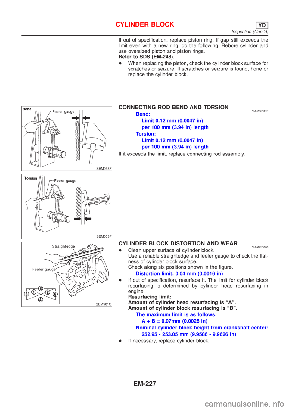
CONNECTING ROD BEND AND TORSIONNLEM0073S04Bend:
Limit 0.12 mm (0.0047 in)
per 100 mm (3.94 in) length
Torsion:
Limit 0.12 mm (0.0047 in)
per 100 mm (3.94 in) length
If it exceeds the limit, replace connecting rod assembly.
SEM501G
CYLINDER BLOCK DISTORTION AND WEARNLEM0073S05+Clean upper surface of cylinder block.
Use a reliable straightedge and feeler gauge to check the flat-
ness of cylinder block surface.
Check along six positions shown in the figure.
Distortion limit: 0.04 mm (0.0016 in)
+If out of specification, resurface it. The limit for cylinder block
resurfacing is determined by cylinder head resurfacing in
engine.
Resurfacing limit:
Amount of cylinder head resurfacing is ªAº.
Amount of cylinder block resurfacing is ªBº.
The maximum limit is as follows:
A + B = 0.07mm (0.0028 in)
Nominal cylinder block height from crankshaft center:
252.95 - 253.05 mm (9.9586 - 9.9626 in)
+If necessary, replace cylinder block.
CYLINDER BLOCKYD
Inspection (Cont'd)
EM-227
Page 2499 of 3051
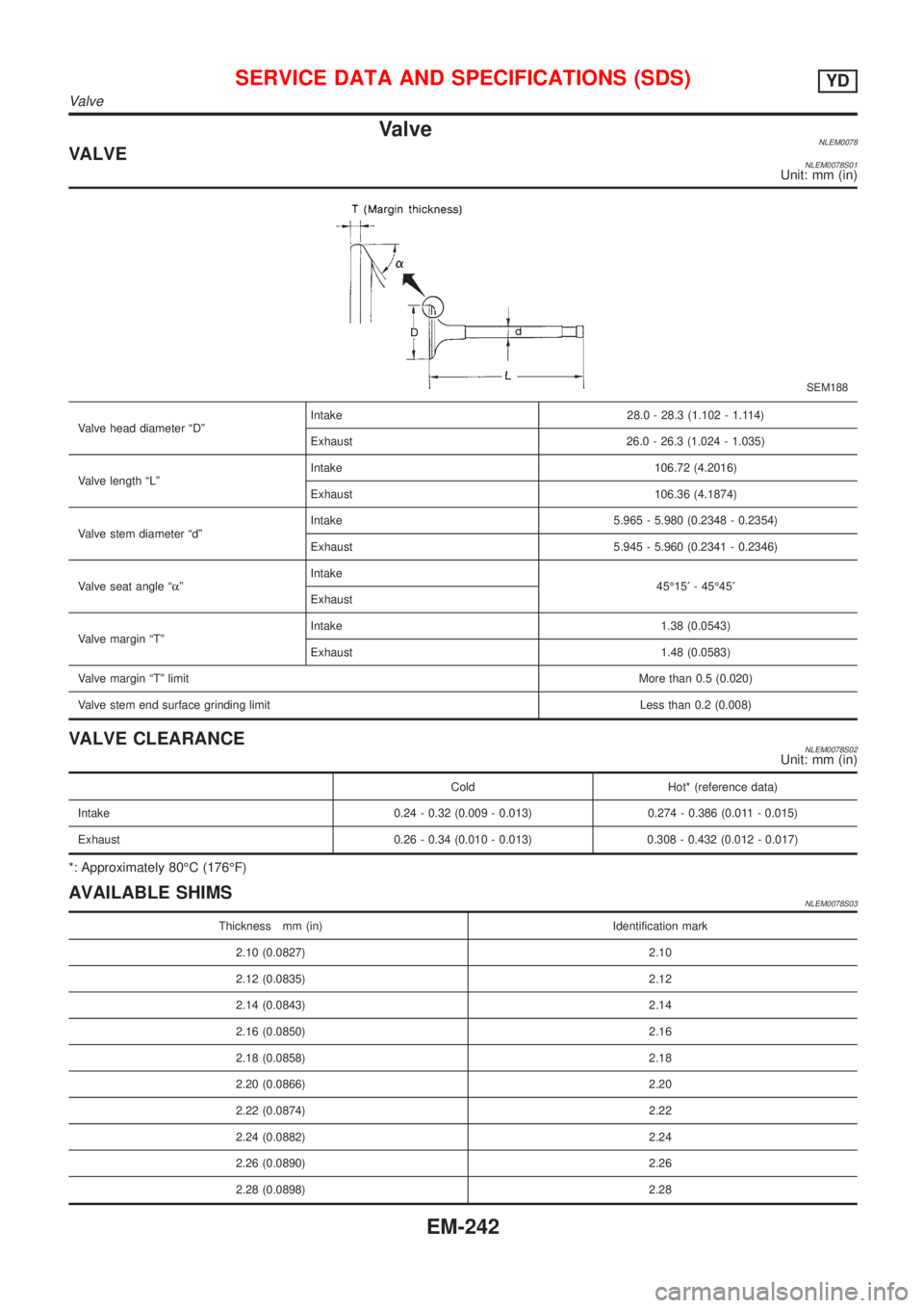
ValveNLEM0078VALVENLEM0078S01Unit: mm (in)
SEM188
Valve head diameter ªDºIntake 28.0 - 28.3 (1.102 - 1.114)
Exhaust 26.0 - 26.3 (1.024 - 1.035)
Valve length ªLºIntake 106.72 (4.2016)
Exhaust 106.36 (4.1874)
Valve stem diameter ªdºIntake 5.965 - 5.980 (0.2348 - 0.2354)
Exhaust 5.945 - 5.960 (0.2341 - 0.2346)
Valve seat angle ªaºIntake
45É15¢- 45É45¢
Exhaust
Valve margin ªTºIntake 1.38 (0.0543)
Exhaust 1.48 (0.0583)
Valve margin ªTº limitMore than 0.5 (0.020)
Valve stem end surface grinding limit Less than 0.2 (0.008)
VALVE CLEARANCENLEM0078S02Unit: mm (in)
Cold Hot* (reference data)
Intake 0.24 - 0.32 (0.009 - 0.013) 0.274 - 0.386 (0.011 - 0.015)
Exhaust 0.26 - 0.34 (0.010 - 0.013) 0.308 - 0.432 (0.012 - 0.017)
*: Approximately 80ÉC (176ÉF)
AVAILABLE SHIMSNLEM0078S03
Thickness mm (in) Identification mark
2.10 (0.0827) 2.10
2.12 (0.0835) 2.12
2.14 (0.0843) 2.14
2.16 (0.0850) 2.16
2.18 (0.0858) 2.18
2.20 (0.0866) 2.20
2.22 (0.0874) 2.22
2.24 (0.0882) 2.24
2.26 (0.0890) 2.26
2.28 (0.0898) 2.28
SERVICE DATA AND SPECIFICATIONS (SDS)YD
Valve
EM-242
Page 2501 of 3051
Lifter guide inner diameter 30.000 - 30.021 (1.1181 - 1.1819)
Clearance between lifter and lifter guide 0.025 - 0.061 (0.0010 - 0.0024)
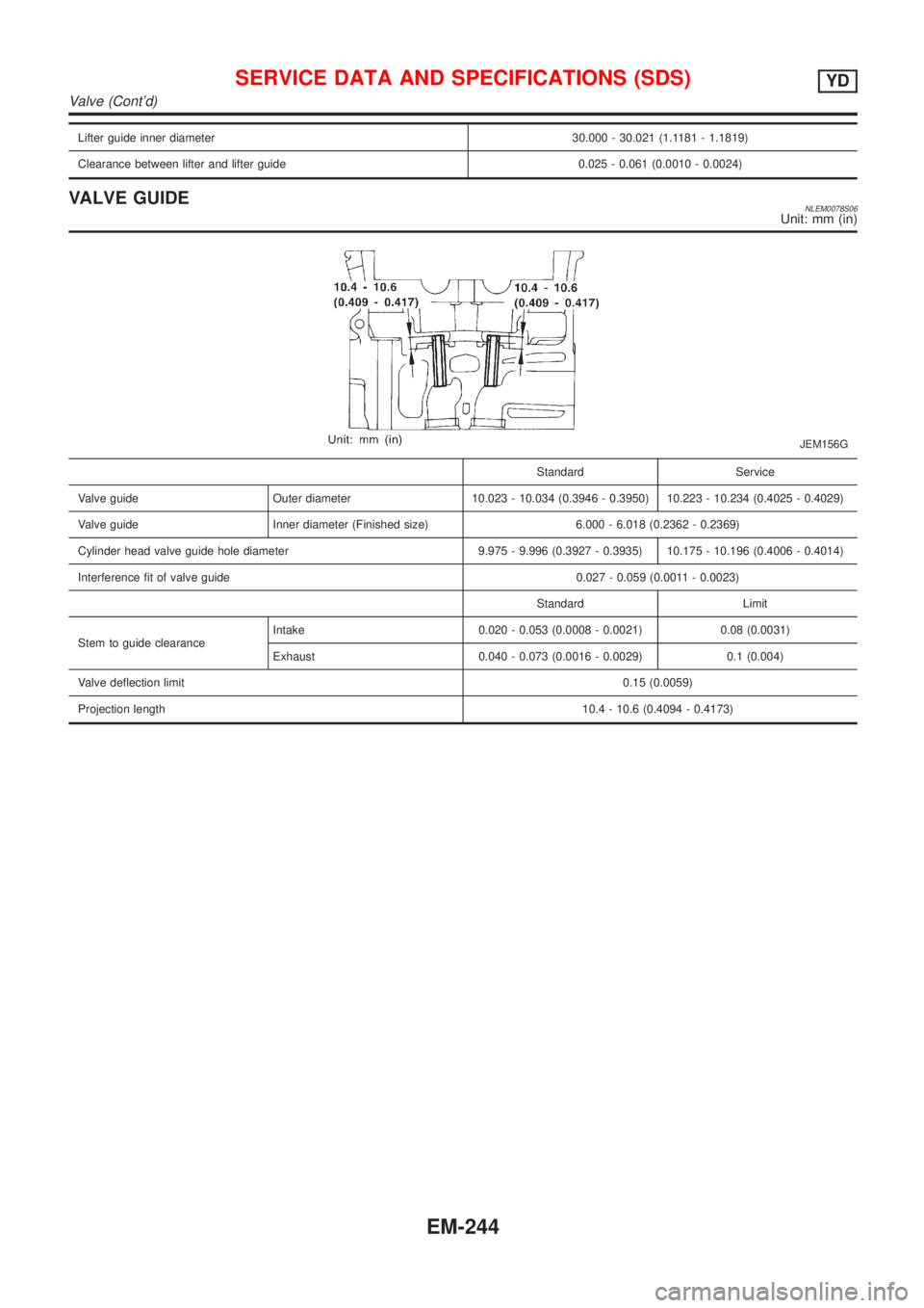
VALVE GUIDENLEM0078S06Unit: mm (in)
JEM156G
Standard Service
Valve guide Outer diameter 10.023 - 10.034 (0.3946 - 0.3950) 10.223 - 10.234 (0.4025 - 0.4029)
Valve guide Inner diameter (Finished size) 6.000 - 6.018 (0.2362 - 0.2369)
Cylinder head valve guide hole diameter 9.975 - 9.996 (0.3927 - 0.3935) 10.175 - 10.196 (0.4006 - 0.4014)
Interference fit of valve guide 0.027 - 0.059 (0.0011 - 0.0023)
Standard Limit
Stem to guide clearanceIntake 0.020 - 0.053 (0.0008 - 0.0021) 0.08 (0.0031)
Exhaust 0.040 - 0.073 (0.0016 - 0.0029) 0.1 (0.004)
Valve deflection limit0.15 (0.0059)
Projection length10.4 - 10.6 (0.4094 - 0.4173)
SERVICE DATA AND SPECIFICATIONS (SDS)YD
Valve (Cont'd)
EM-244
Page 2546 of 3051
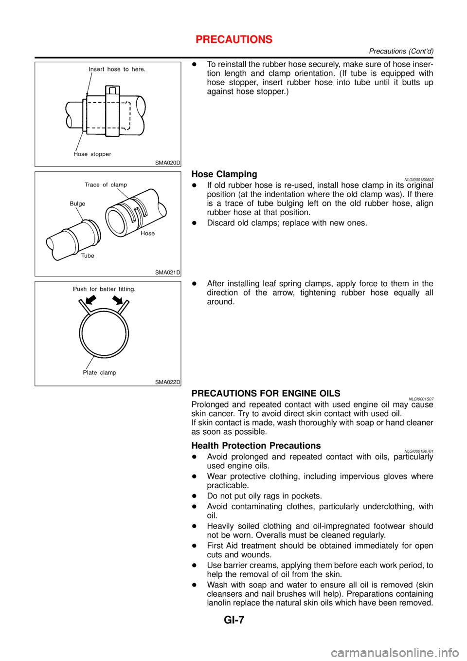
SMA020D
+To reinstall the rubber hose securely, make sure of hose inser-
tion length and clamp orientation. (If tube is equipped with
hose stopper, insert rubber hose into tube until it butts up
against hose stopper.)
SMA021D
Hose ClampingNLGI0001S0602+If old rubber hose is re-used, install hose clamp in its original
position (at the indentation where the old clamp was). If there
is a trace of tube bulging left on the old rubber hose, align
rubber hose at that position.
+Discard old clamps; replace with new ones.
SMA022D
+After installing leaf spring clamps, apply force to them in the
direction of the arrow, tightening rubber hose equally all
around.
PRECAUTIONS FOR ENGINE OILSNLGI0001S07Prolonged and repeated contact with used engine oil may cause
skin cancer. Try to avoid direct skin contact with used oil.
If skin contact is made, wash thoroughly with soap or hand cleaner
as soon as possible.
Health Protection PrecautionsNLGI0001S0701+Avoid prolonged and repeated contact with oils, particularly
used engine oils.
+Wear protective clothing, including impervious gloves where
practicable.
+Do not put oily rags in pockets.
+Avoid contaminating clothes, particularly underclothing, with
oil.
+Heavily soiled clothing and oil-impregnated footwear should
not be worn. Overalls must be cleaned regularly.
+First Aid treatment should be obtained immediately for open
cuts and wounds.
+Use barrier creams, applying them before each work period, to
help the removal of oil from the skin.
+Wash with soap and water to ensure all oil is removed (skin
cleansers and nail brushes will help). Preparations containing
lanolin replace the natural skin oils which have been removed.
PRECAUTIONS
Precautions (Cont’d)
GI-7
Page 2580 of 3051
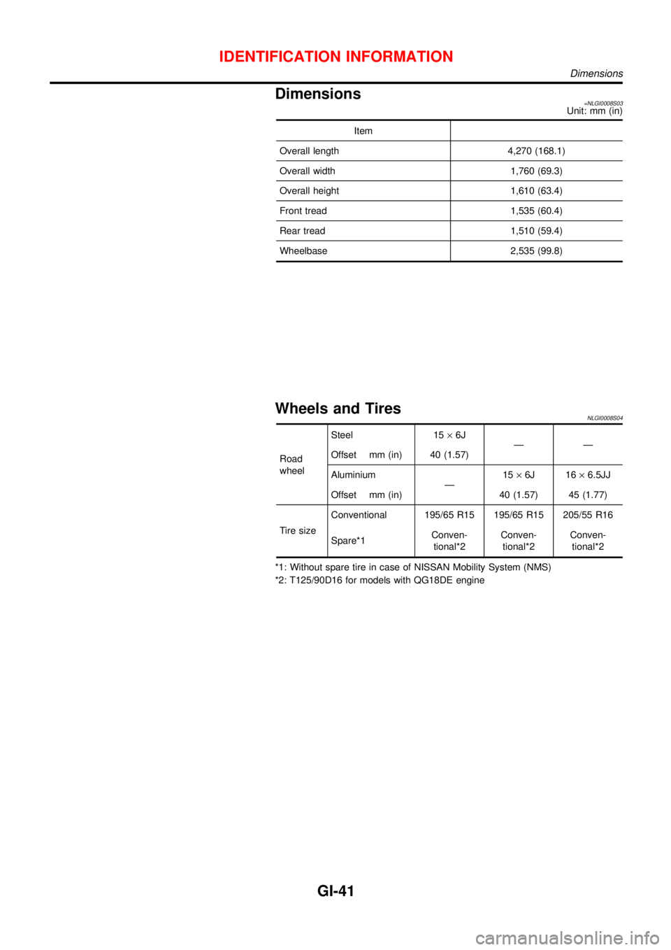
Dimensions=NLGI0008S03Unit: mm (in)
Item
Overall length 4,270 (168.1)
Overall width 1,760 (69.3)
Overall height 1,610 (63.4)
Front tread 1,535 (60.4)
Rear tread 1,510 (59.4)
Wheelbase 2,535 (99.8)
Wheels and TiresNLGI0008S04
Road
wheelSteel 15×6J
——
Offset mm (in) 40 (1.57)
Aluminium
—15×6J 16×6.5JJ
Offset mm (in) 40 (1.57) 45 (1.77)
Tire sizeConventional 195/65 R15 195/65 R15 205/55 R16
Spare*1Conven-
tional*2Conven-
tional*2Conven-
tional*2
*1: Without spare tire in case of NISSAN Mobility System (NMS)
*2: T125/90D16 for models with QG18DE engine
IDENTIFICATION INFORMATION
Dimensions
GI-41
Page 2700 of 3051
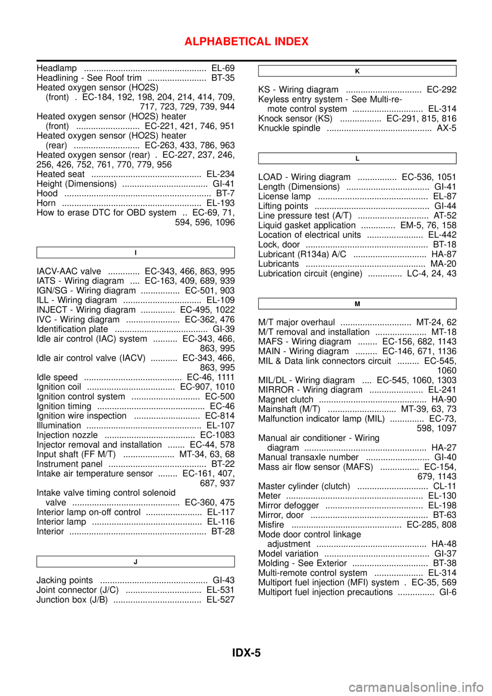
Headlamp .................................................. EL-69
Headlining - See Roof trim ........................ BT-35
Heated oxygen sensor (HO2S)
(front) . EC-184, 192, 198, 204, 214, 414, 709,
717, 723, 729, 739, 944
Heated oxygen sensor (HO2S) heater
(front) .......................... EC-221, 421, 746, 951
Heated oxygen sensor (HO2S) heater
(rear) ........................... EC-263, 433, 786, 963
Heated oxygen sensor (rear) . EC-227, 237, 246,
256, 426, 752, 761, 770, 779, 956
Heated seat ............................................. EL-234
Height (Dimensions) ................................... GI-41
Hood ............................................................ BT-7
Horn ......................................................... EL-193
How to erase DTC for OBD system .. EC-69, 71,
594, 596, 1096
I
IACV-AAC valve ............. EC-343, 466, 863, 995
IATS - Wiring diagram .... EC-163, 409, 689, 939
IGN/SG - Wiring diagram ................ EC-501, 903
ILL - Wiring diagram ................................ EL-109
INJECT - Wiring diagram .............. EC-495, 1022
IVC - Wiring diagram ...................... EC-362, 476
Identification plate ...................................... GI-39
Idle air control (IAC) system .......... EC-343, 466,
863, 995
Idle air control valve (IACV) ........... EC-343, 466,
863, 995
Idle speed ........................................ EC-46,1111
Ignition coil .................................... EC-907, 1010
Ignition control system ............................ EC-500
Ignition timing ............................................ EC-46
Ignition wire inspection ........................... EC-814
Illumination ............................................... EL-107
Injection nozzle ..................................... EC-1083
Injector removal and installation ....... EC-44, 578
Input shaft (FF M/T) ..................... MT-34, 63, 68
Instrument panel ........................................ BT-22
Intake air temperature sensor ........ EC-161, 407,
687, 937
Intake valve timing control solenoid
valve ............................................ EC-360, 475
Interior lamp on-off control ....................... EL-117
Interior lamp ............................................. EL-116
Interior ........................................................ BT-28
J
Jacking points ............................................ GI-43
Joint connector (J/C) ............................... EL-531
Junction box (J/B) .................................... EL-527
K
KS - Wiring diagram ............................... EC-292
Keyless entry system - See Multi-re-
mote control system ............................. EL-314
Knock sensor (KS) ................. EC-291, 815, 816
Knuckle spindle ........................................... AX-5
L
LOAD - Wiring diagram ................ EC-536, 1051
Length (Dimensions) .................................. GI-41
License lamp ............................................. EL-87
Lifting points ............................................... GI-44
Line pressure test (A/T) ............................. AT-52
Liquid gasket application .............. EM-5, 76, 158
Location of electrical units ....................... EL-442
Lock, door .................................................. BT-18
Lubricant (R134a) A/C .............................. HA-87
Lubricants ................................................. MA-20
Lubrication circuit (engine) .............. LC-4, 24, 43
M
M/T major overhaul ............................. MT-24, 62
M/T removal and installation ..................... MT-18
MAFS - Wiring diagram ........ EC-156, 682, 1143
MAIN - Wiring diagram ......... EC-146, 671, 1136
MIL & Data link connectors circuit ......... EC-545,
1060
MIL/DL - Wiring diagram .... EC-545, 1060, 1303
MIRROR - Wiring diagram ...................... EL-241
Magnet clutch ............................................ HA-90
Mainshaft (M/T) ............................ MT-39, 63, 73
Malfunction indicator lamp (MIL) .............. EC-73,
598, 1097
Manual air conditioner - Wiring
diagram .................................................. HA-27
Manual transaxle number .......................... GI-40
Mass air flow sensor (MAFS) ................ EC-154,
679, 1143
Master cylinder (clutch) ............................. CL-11
Meter ........................................................ EL-130
Mirror defogger ........................................ EL-198
Mirror, door ................................................ BT-63
Misfire ............................................. EC-285, 808
Mode door control linkage
adjustment ............................................. HA-48
Model variation ........................................... GI-37
Molding - See Exterior ............................... BT-38
Multi-remote control system .................... EL-314
Multiport fuel injection (MFI) system . EC-35, 569
Multiport fuel injection precautions ............... GI-6
ALPHABETICAL INDEX
IDX-5
Page 2825 of 3051
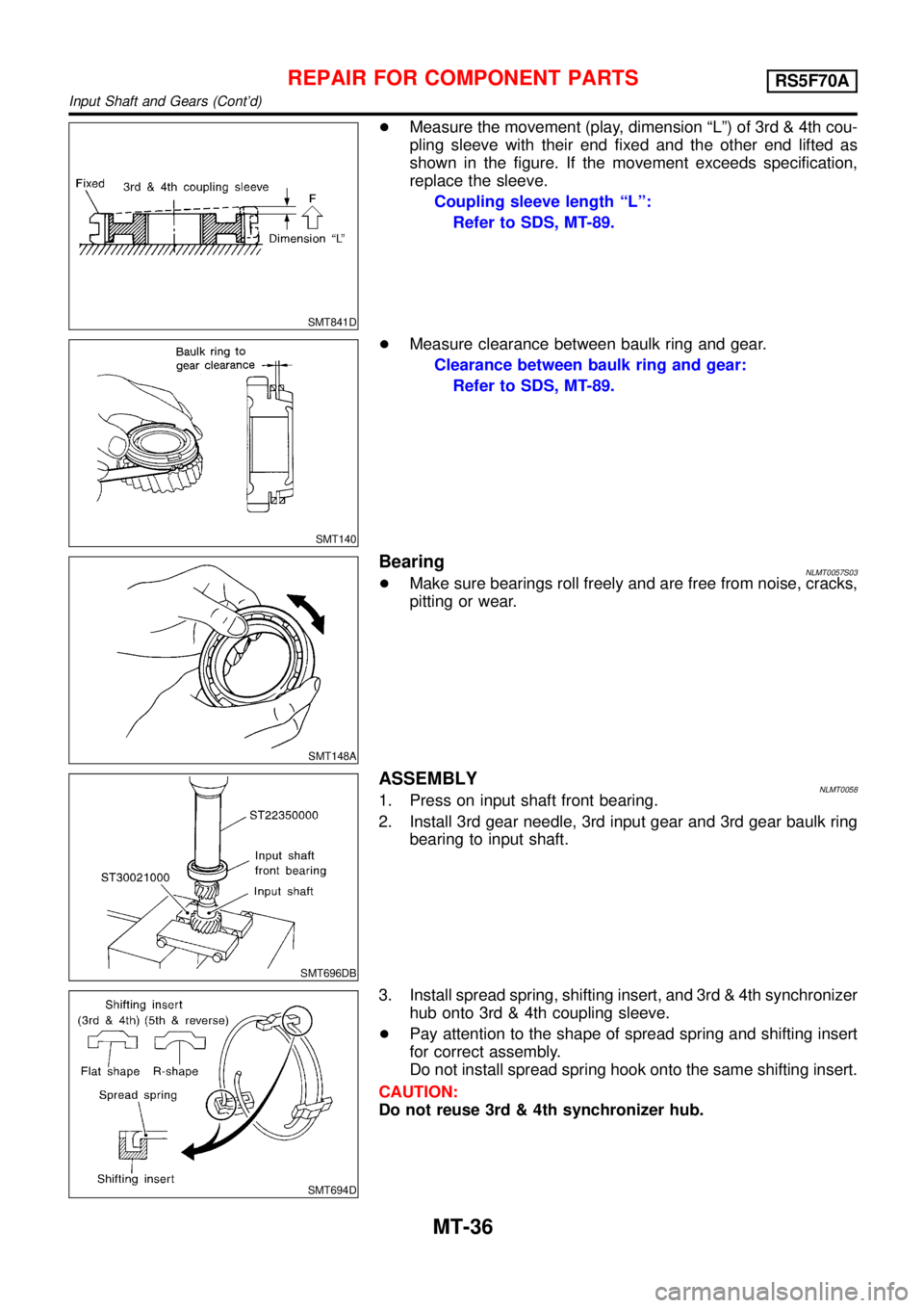
SMT841D
+Measure the movement (play, dimension“L”) of 3rd & 4th cou-
pling sleeve with their end fixed and the other end lifted as
shown in the figure. If the movement exceeds specification,
replace the sleeve.
Coupling sleeve length“L”:
Refer to SDS, MT-89.
SMT140
+Measure clearance between baulk ring and gear.
Clearance between baulk ring and gear:
Refer to SDS, MT-89.
SMT148A
BearingNLMT0057S03+Make sure bearings roll freely and are free from noise, cracks,
pitting or wear.
SMT696DB
ASSEMBLYNLMT00581. Press on input shaft front bearing.
2. Install 3rd gear needle, 3rd input gear and 3rd gear baulk ring
bearing to input shaft.
SMT694D
3. Install spread spring, shifting insert, and 3rd & 4th synchronizer
hub onto 3rd & 4th coupling sleeve.
+Pay attention to the shape of spread spring and shifting insert
for correct assembly.
Do not install spread spring hook onto the same shifting insert.
CAUTION:
Do not reuse 3rd & 4th synchronizer hub.
REPAIR FOR COMPONENT PARTSRS5F70A
Input Shaft and Gears (Cont’d)
MT-36
Page 2830 of 3051
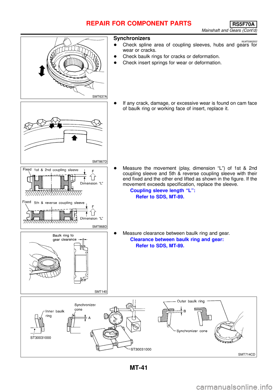
SMT637A
SynchronizersNLMT0060S02+Check spline area of coupling sleeves, hubs and gears for
wear or cracks.
+Check baulk rings for cracks or deformation.
+Check insert springs for wear or deformation.
SMT867D
+If any crack, damage, or excessive wear is found on cam face
of baulk ring or working face of insert, replace it.
SMT868D
+Measure the movement (play, dimension“L”)of1st&2nd
coupling sleeve and 5th & reverse coupling sleeve with their
end fixed and the other end lifted as shown in the figure. If the
movement exceeds specification, replace the sleeve.
Coupling sleeve length“L”:
Refer to SDS, MT-89.
SMT140
+Measure clearance between baulk ring and gear.
Clearance between baulk ring and gear:
Refer to SDS, MT-89.
SMT714CD
REPAIR FOR COMPONENT PARTSRS5F70A
Mainshaft and Gears (Cont’d)
MT-41