2001 NISSAN ALMERA TINO power steering
[x] Cancel search: power steeringPage 952 of 3051
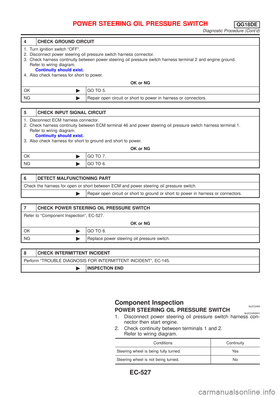
4 CHECK GROUND CIRCUIT
1. Turn ignition switch ªOFFº.
2. Disconnect power steering oil pressure switch harness connector.
3. Check harness continuity between power steering oil pressure switch harness terminal 2 and engine ground.
Refer to wiring diagram.
Continuity should exist.
4. Also check harness for short to power.
OK or NG
OK©GO TO 5.
NG©Repair open circuit or short to power in harness or connectors.
5 CHECK INPUT SIGNAL CIRCUIT
1. Disconnect ECM harness connector.
2. Check harness continuity between ECM terminal 46 and power steering oil pressure switch harness terminal 1.
Refer to wiring diagram.
Continuity should exist.
3. Also check harness for short to ground and short to power.
OK or NG
OK©GO TO 7.
NG©GO TO 6.
6 DETECT MALFUNCTIONING PART
Check the harness for open or short between ECM and power steering oil pressure switch.
©Repair open circuit or short to ground or short to power in harness or connectors.
7 CHECK POWER STEERING OIL PRESSURE SWITCH
Refer to ªComponent Inspectionº, EC-527.
OK or NG
OK©GO TO 8.
NG©Replace power steering oil pressure switch.
8 CHECK INTERMITTENT INCIDENT
Perform ªTROUBLE DIAGNOSIS FOR INTERMITTENT INCIDENTº, EC-145.
©INSPECTION END
Component InspectionNLEC0455POWER STEERING OIL PRESSURE SWITCHNLEC0455S011. Disconnect power steering oil pressure switch harness con-
nector then start engine.
2. Check continuity between terminals 1 and 2.
Refer to wiring diagram.
Conditions Continuity
Steering wheel is being fully turned. Yes
Steering wheel is not being turned. No
POWER STEERING OIL PRESSURE SWITCHQG18DE
Diagnostic Procedure (Cont'd)
EC-527
Page 953 of 3051

If NG, replace power steering oil pressure switch.
POWER STEERING OIL PRESSURE SWITCHQG18DE
Component Inspection (Cont'd)
EC-528
Page 993 of 3051
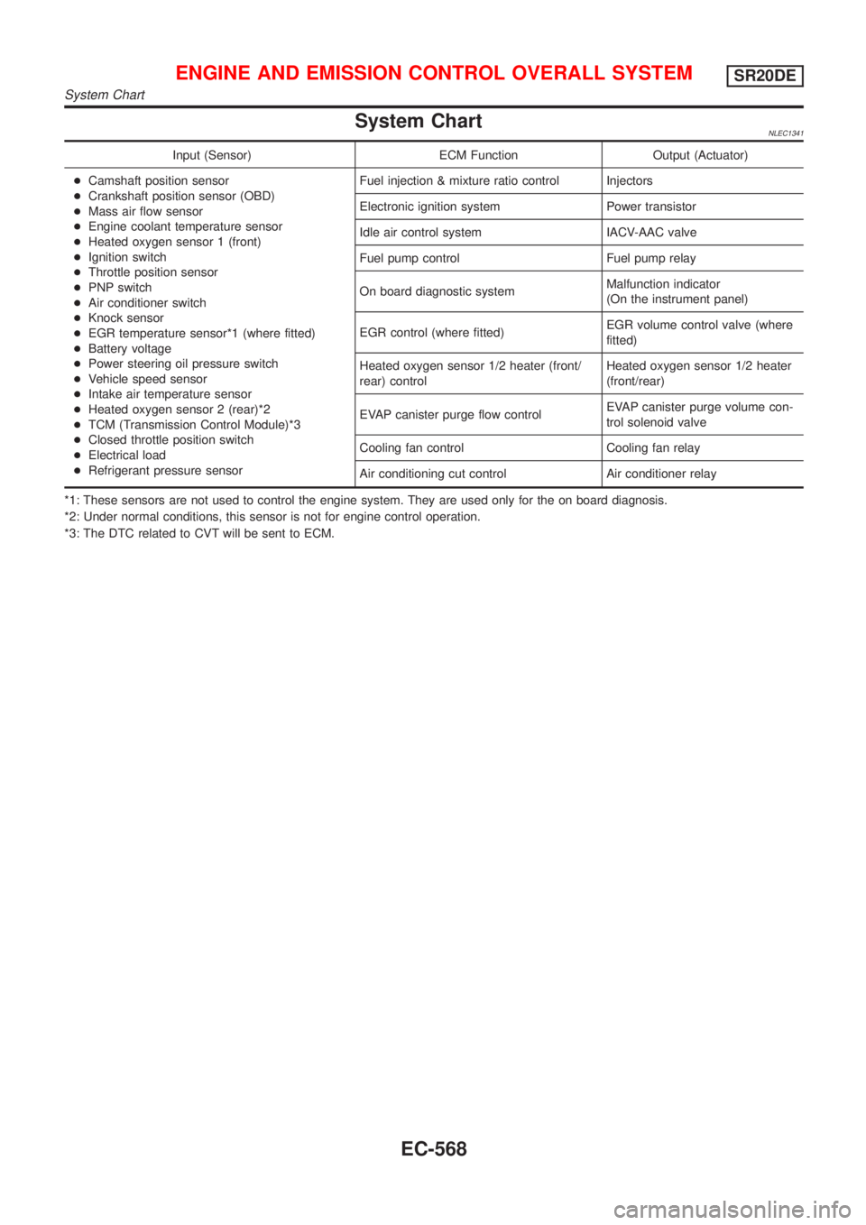
System ChartNLEC1341
Input (Sensor) ECM Function Output (Actuator)
+Camshaft position sensor
+Crankshaft position sensor (OBD)
+Mass air flow sensor
+Engine coolant temperature sensor
+Heated oxygen sensor 1 (front)
+Ignition switch
+Throttle position sensor
+PNP switch
+Air conditioner switch
+Knock sensor
+EGR temperature sensor*1 (where fitted)
+Battery voltage
+Power steering oil pressure switch
+Vehicle speed sensor
+Intake air temperature sensor
+Heated oxygen sensor 2 (rear)*2
+TCM (Transmission Control Module)*3
+Closed throttle position switch
+Electrical load
+Refrigerant pressure sensorFuel injection & mixture ratio control Injectors
Electronic ignition system Power transistor
Idle air control system IACV-AAC valve
Fuel pump control Fuel pump relay
On board diagnostic systemMalfunction indicator
(On the instrument panel)
EGR control (where fitted)EGR volume control valve (where
fitted)
Heated oxygen sensor 1/2 heater (front/
rear) controlHeated oxygen sensor 1/2 heater
(front/rear)
EVAP canister purge flow controlEVAP canister purge volume con-
trol solenoid valve
Cooling fan control Cooling fan relay
Air conditioning cut control Air conditioner relay
*1: These sensors are not used to control the engine system. They are used only for the on board diagnosis.
*2: Under normal conditions, this sensor is not for engine control operation.
*3: The DTC related to CVT will be sent to ECM.
ENGINE AND EMISSION CONTROL OVERALL SYSTEMSR20DE
System Chart
EC-568
Page 994 of 3051
Multiport Fuel Injection (MFI) System
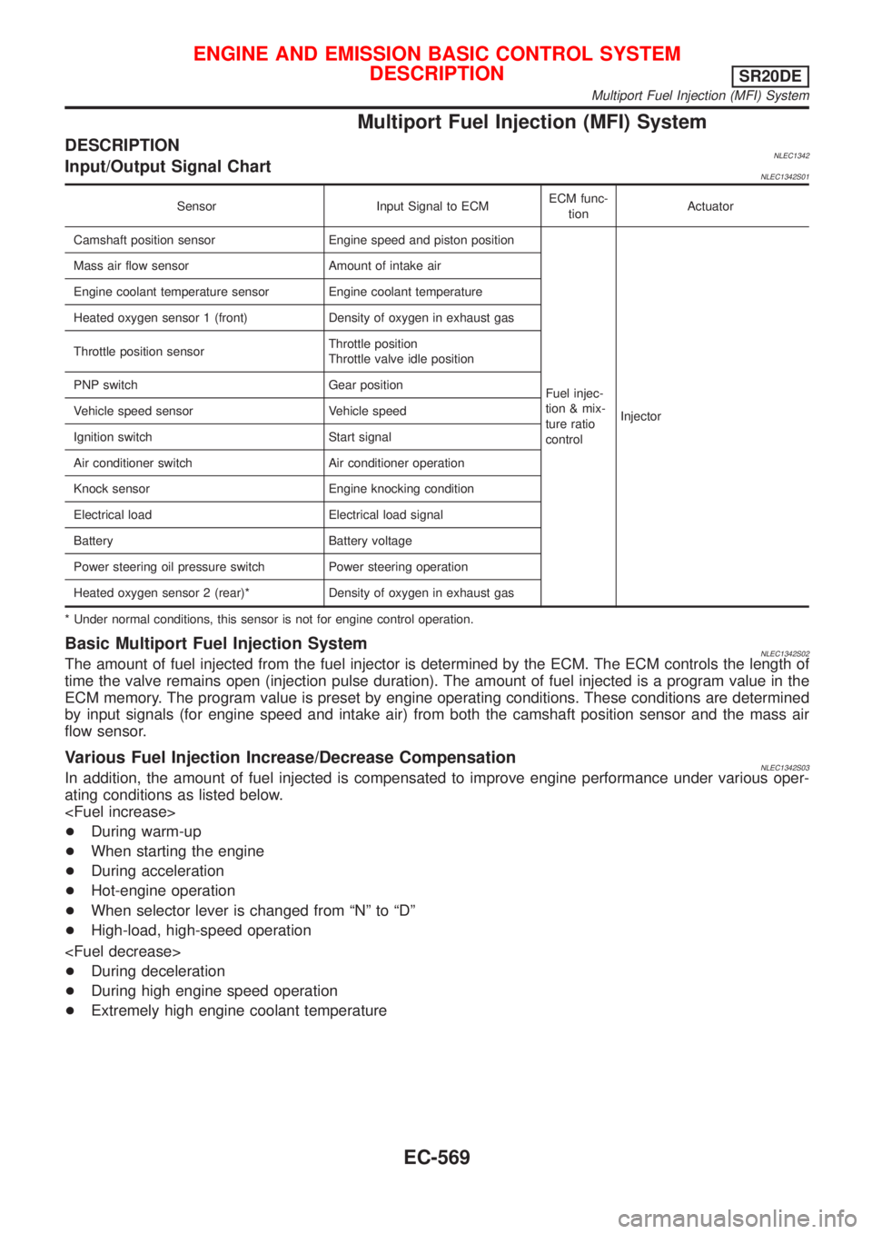
DESCRIPTIONNLEC1342Input/Output Signal ChartNLEC1342S01
Sensor Input Signal to ECMECM func-
tionActuator
Camshaft position sensor Engine speed and piston position
Fuel injec-
tion & mix-
ture ratio
controlInjector Mass air flow sensor Amount of intake air
Engine coolant temperature sensor Engine coolant temperature
Heated oxygen sensor 1 (front) Density of oxygen in exhaust gas
Throttle position sensorThrottle position
Throttle valve idle position
PNP switch Gear position
Vehicle speed sensor Vehicle speed
Ignition switch Start signal
Air conditioner switch Air conditioner operation
Knock sensor Engine knocking condition
Electrical load Electrical load signal
Battery Battery voltage
Power steering oil pressure switch Power steering operation
Heated oxygen sensor 2 (rear)* Density of oxygen in exhaust gas
* Under normal conditions, this sensor is not for engine control operation.
Basic Multiport Fuel Injection SystemNLEC1342S02The amount of fuel injected from the fuel injector is determined by the ECM. The ECM controls the length of
time the valve remains open (injection pulse duration). The amount of fuel injected is a program value in the
ECM memory. The program value is preset by engine operating conditions. These conditions are determined
by input signals (for engine speed and intake air) from both the camshaft position sensor and the mass air
flow sensor.
Various Fuel Injection Increase/Decrease CompensationNLEC1342S03In addition, the amount of fuel injected is compensated to improve engine performance under various oper-
ating conditions as listed below.
+During warm-up
+When starting the engine
+During acceleration
+Hot-engine operation
+When selector lever is changed from ªNº to ªDº
+High-load, high-speed operation
+During deceleration
+During high engine speed operation
+Extremely high engine coolant temperature
ENGINE AND EMISSION BASIC CONTROL SYSTEM
DESCRIPTION
SR20DE
Multiport Fuel Injection (MFI) System
EC-569
Page 997 of 3051
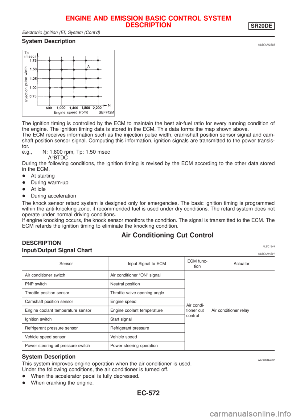
System DescriptionNLEC1343S02
SEF742M
The ignition timing is controlled by the ECM to maintain the best air-fuel ratio for every running condition of
the engine. The ignition timing data is stored in the ECM. This data forms the map shown above.
The ECM receives information such as the injection pulse width, crankshaft position sensor signal and cam-
shaft position sensor signal. Computing this information, ignition signals are transmitted to the power transis-
tor.
e.g., N: 1,800 rpm, Tp: 1.50 msec
AÉBTDC
During the following conditions, the ignition timing is revised by the ECM according to the other data stored
in the ECM.
+At starting
+During warm-up
+At idle
+During acceleration
The knock sensor retard system is designed only for emergencies. The basic ignition timing is programmed
within the anti-knocking zone, if recommended fuel is used under dry conditions. The retard system does not
operate under normal driving conditions.
If engine knocking occurs, the knock sensor monitors the condition. The signal is transmitted to the ECM. The
ECM retards the ignition timing to eliminate the knocking condition.
Air Conditioning Cut Control
DESCRIPTIONNLEC1344Input/Output Signal ChartNLEC1344S01
Sensor Input Signal to ECMECM func-
tionActuator
Air conditioner switch Air conditioner ªONº signal
Air condi-
tioner cut
controlAir conditioner relay PNP switch Neutral position
Throttle position sensor Throttle valve opening angle
Camshaft position sensor Engine speed
Engine coolant temperature sensor Engine coolant temperature
Ignition switch Start signal
Refrigerant pressure sensor Refrigerant pressure
Vehicle speed sensor Vehicle speed
Power steering oil pressure switch Power steering operation
System DescriptionNLEC1344S02This system improves engine operation when the air conditioner is used.
Under the following conditions, the air conditioner is turned off.
+When the accelerator pedal is fully depressed.
+When cranking the engine.
ENGINE AND EMISSION BASIC CONTROL SYSTEM
DESCRIPTION
SR20DE
Electronic Ignition (EI) System (Cont'd)
EC-572
Page 998 of 3051
+At high engine speeds.
+When the engine coolant temperature becomes excessively high.
+When operating power steering during low engine speed or low vehicle speed.
+When engine speed is excessively low.
+When the refrigerant pressure is excessively high or low.
Fuel Cut Control (at no load & high engine
speed)
DESCRIPTIONNLEC1345Input/Output Signal ChartNLEC1345S01
Sensor Input Signal to ECMECM func-
tionActuator
Vehicle speed sensor Vehicle speed
Fuel cut
controlInjectors PNP switch Neutral position
Throttle position sensor Throttle position
Engine coolant temperature sensor Engine coolant temperature
Camshaft position sensor Engine speed
If the engine speed is above 3,950 rpm with no load, (for example, in Neutral and engine speed over 4,000
rpm) fuel will be cut off after some time. The exact time when the fuel is cut off varies based on engine speed.
Fuel cut will operate until the engine speed reaches 1,150 rpm, then fuel cut is cancelled.
NOTE:
This function is different from deceleration control listed under ªMultiport Fuel Injection (MFI) Systemº,
EC-569.
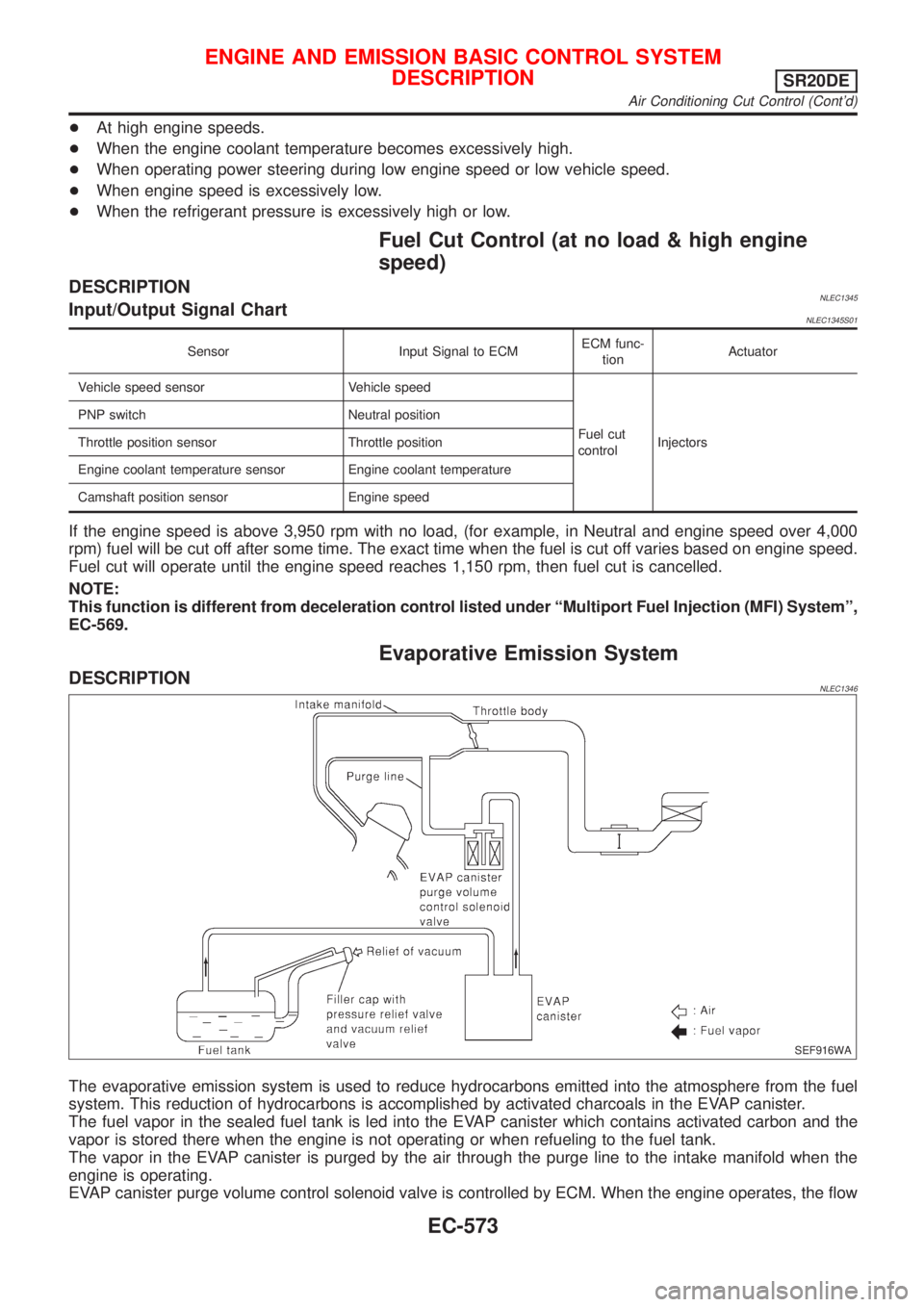
Evaporative Emission System
DESCRIPTIONNLEC1346
SEF916WA
The evaporative emission system is used to reduce hydrocarbons emitted into the atmosphere from the fuel
system. This reduction of hydrocarbons is accomplished by activated charcoals in the EVAP canister.
The fuel vapor in the sealed fuel tank is led into the EVAP canister which contains activated carbon and the
vapor is stored there when the engine is not operating or when refueling to the fuel tank.
The vapor in the EVAP canister is purged by the air through the purge line to the intake manifold when the
engine is operating.
EVAP canister purge volume control solenoid valve is controlled by ECM. When the engine operates, the flow
ENGINE AND EMISSION BASIC CONTROL SYSTEM
DESCRIPTION
SR20DE
Air Conditioning Cut Control (Cont'd)
EC-573
Page 1033 of 3051
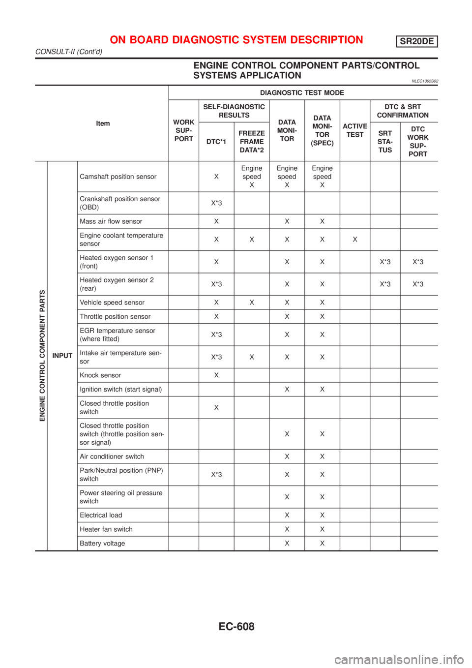
ENGINE CONTROL COMPONENT PARTS/CONTROL
SYSTEMS APPLICATION
NLEC1365S02
ItemDIAGNOSTIC TEST MODE
WORK
SUP-
PORTSELF-DIAGNOSTIC
RESULTS
D ATA
MONI-
TORD ATA
MONI-
TOR
(SPEC)ACTIVE
TESTDTC & SRT
CONFIRMATION
DTC*1FREEZE
FRAME
DATA*2SRT
STA-
TUSDTC
WORK
SUP-
PORT
ENGINE CONTROL COMPONENT PARTS
INPUTCamshaft position sensor XEngine
speed
XEngine
speed
XEngine
speed
X
Crankshaft position sensor
(OBD)X*3
Mass air flow sensor X X X
Engine coolant temperature
sensorXXXXX
Heated oxygen sensor 1
(front)X X X X*3 X*3
Heated oxygen sensor 2
(rear)X*3 X X X*3 X*3
Vehicle speed sensorXXXX
Throttle position sensor X X X
EGR temperature sensor
(where fitted)X*3 X X
Intake air temperature sen-
sorX*3 X X X
Knock sensor X
Ignition switch (start signal) X X
Closed throttle position
switchX
Closed throttle position
switch (throttle position sen-
sor signal)XX
Air conditioner switch X X
Park/Neutral position (PNP)
switchX*3 X X
Power steering oil pressure
switchXX
Electrical load X X
Heater fan switch X X
Battery voltage X X
ON BOARD DIAGNOSTIC SYSTEM DESCRIPTIONSR20DE
CONSULT-II (Cont'd)
EC-608
Page 1037 of 3051
![NISSAN ALMERA TINO 2001 Service Repair Manual Monitored item [Unit]ECM
input
signalsMain
signalsDescription Remarks
INT/A TEMP SE
[ÉC] or [ÉF]jj+The intake air temperature determined by the
signal voltage of the intake air temperature
sensor is NISSAN ALMERA TINO 2001 Service Repair Manual Monitored item [Unit]ECM
input
signalsMain
signalsDescription Remarks
INT/A TEMP SE
[ÉC] or [ÉF]jj+The intake air temperature determined by the
signal voltage of the intake air temperature
sensor is](/manual-img/5/57352/w960_57352-1036.png)
Monitored item [Unit]ECM
input
signalsMain
signalsDescription Remarks
INT/A TEMP SE
[ÉC] or [ÉF]jj+The intake air temperature determined by the
signal voltage of the intake air temperature
sensor is indicated.
EGR TEMP SEN [V]
(where fitted)jj+The signal voltage of the EGR temperature
sensor is displayed.
START SIGNAL
[ON/OFF]jj+Indicates [ON/OFF] condition from the starter
signal.+After starting the engine, [OFF] is
displayed regardless of the starter
signal.
CLSD THL POS
[ON/OFF]jj+Indicates idle position [ON/OFF] computed by
ECM according to the throttle position sensor
signal.
AIR COND SIG
[ON/OFF]jj+Indicates [ON/OFF] condition of the air condi-
tioner switch as determined by the air condi-
tioning signal.
P/N POSI SW
[ON/OFF]jj+Indicates [ON/OFF] condition from the PNP
switch signal.
PW/ST SIGNAL
[ON/OFF]jj+Indicates [ON/OFF] condition of the power
steering oil pressure switch determined by
the power steering oil pressure switch signal.
LOAD SIGNAL
[ON/OFF]jj+Indicates [ON/OFF] condition from the electri-
cal load signal and/or lighting switch.
ON ... rear defogger is operating and/or light-
ing switch is on.
OFF ... rear defogger is not operating and
lighting switch is not on.
IGNITION SW
[ON/OFF]j+Indicates [ON/OFF] condition from ignition
switch.
INJ PULSE-B1
[msec]j+Indicates the actual fuel injection pulse width
compensated by ECM according to the input
signals.+When the engine is stopped, a cer-
tain computed value is indicated.
IGN TIMING [BTDC]j+Indicates the ignition timing computed by
ECM according to the input signals.
CAL/LD VALUE [%]+ªCalculated load valueº indicates the value of
the current airflow divided by peak airflow.
ABSOL TH.P/S [%]+ªAbsolute throttle position sensorº indicates
the throttle opening computed by ECM
according to the signal voltage of the throttle
position sensor.
MASS AIRFLOW
[gm/s]+Indicates the mass airflow computed by ECM
according to the signal voltage of the mass
air flow sensor.
IACV-AAC/V [step]j+Indicates the IACV-AAC valve control value
computed by ECM according to the input sig-
nals.
PURG VOL C/V [%]+Indicates the EVAP canister purge volume
control solenoid valve computed by the ECM
according to the inpuct signals.
+The opening becomes larger as the value
increases.
ON BOARD DIAGNOSTIC SYSTEM DESCRIPTIONSR20DE
CONSULT-II (Cont'd)
EC-612