2001 NISSAN ALMERA TINO power steering
[x] Cancel search: power steeringPage 1467 of 3051
4 CHECK GROUND CIRCUIT
1. Turn ignition switch ªOFFº.
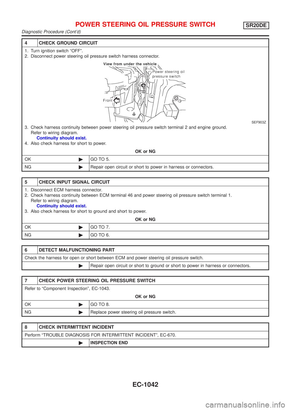
2. Disconnect power steering oil pressure switch harness connector.
SEF903Z
3. Check harness continuity between power steering oil pressure switch terminal 2 and engine ground.
Refer to wiring diagram.
Continuity should exist.
4. Also check harness for short to power.
OK or NG
OK©GO TO 5.
NG©Repair open circuit or short to power in harness or connectors.
5 CHECK INPUT SIGNAL CIRCUIT
1. Disconnect ECM harness connector.
2. Check harness continuity between ECM terminal 46 and power steering oil pressure switch terminal 1.
Refer to wiring diagram.
Continuity should exist.
3. Also check harness for short to ground and short to power.
OK or NG
OK©GO TO 7.
NG©GO TO 6.
6 DETECT MALFUNCTIONING PART
Check the harness for open or short between ECM and power steering oil pressure switch.
©Repair open circuit or short to ground or short to power in harness or connectors.
7 CHECK POWER STEERING OIL PRESSURE SWITCH
Refer to ªComponent Inspectionº, EC-1043.
OK or NG
OK©GO TO 8.
NG©Replace power steering oil pressure switch.
8 CHECK INTERMITTENT INCIDENT
Perform ªTROUBLE DIAGNOSIS FOR INTERMITTENT INCIDENTº, EC-670.
©INSPECTION END
POWER STEERING OIL PRESSURE SWITCHSR20DE
Diagnostic Procedure (Cont'd)
EC-1042
Page 1468 of 3051
Component InspectionNLEC1877POWER STEERING OIL PRESSURE SWITCHNLEC1877S011. Disconnect power steering oil pressure switch harness con-
nector then start engine.
2. Check continuity between terminals 1 and 2.
Refer to wiring diagram.
Conditions Continuity
Steering wheel is being fully turned. Yes
Steering wheel is not being turned. No
If NG, replace power steering oil pressure switch.
POWER STEERING OIL PRESSURE SWITCHSR20DE
Component Inspection
EC-1043
Page 1491 of 3051
Precautions for Supplemental Restraint System
(SRS) ªAIR BAGº and ªSEAT BELT
PRE-TENSIONERº
NLEC1263The Supplemental Restraint System ªAIR BAGº and ªSEAT BELT PRE-TENSIONERº, used along with a seat
belt, help to reduce the risk or severity of injury to the driver and front passenger in a frontal collision. The
Supplemental Restraint System consists of air bag modules (located in the center of the steering wheel and
on the instrument panel on the passenger side), seat belt pre-tensioners, a diagnosis sensor unit, warning
lamp, wiring harness and spiral cable.
In addition to the supplemental air bag modules for a frontal collision, the supplemental side air bag used along
with the seat belt helps to reduce the risk or severity of injury to the driver and front passenger in a side col-
lision. The supplemental side air bag consists of air bag modules (located in the outer side of front seats),
satellite sensor, diagnosis sensor unit (one of components of supplemental air bags for a frontal collision),
wiring harness, warning lamp (one of components of supplemental air bags for a frontal collision). Information
necessary to service the system safely is included in theRS sectionof this Service Manual.
WARNING:
+To avoid rendering the SRS inoperative, which could increase the risk of personal injury or death
in the event of a collision which would result in air bag inflation, all maintenance must be performed
by an authorized NISSAN dealer.
+Improper maintenance, including incorrect removal and installation of the SRS, can lead to per-
sonal injury caused by unintentional activation of the system.
+Do not use electrical test equipment on any circuit related to the SRS unless instructed to in this
Service Manual. SRS wiring harnesses can be identified with yellow harness connector (and with
yellow harness protector or yellow insulation tape before the harness connectors).
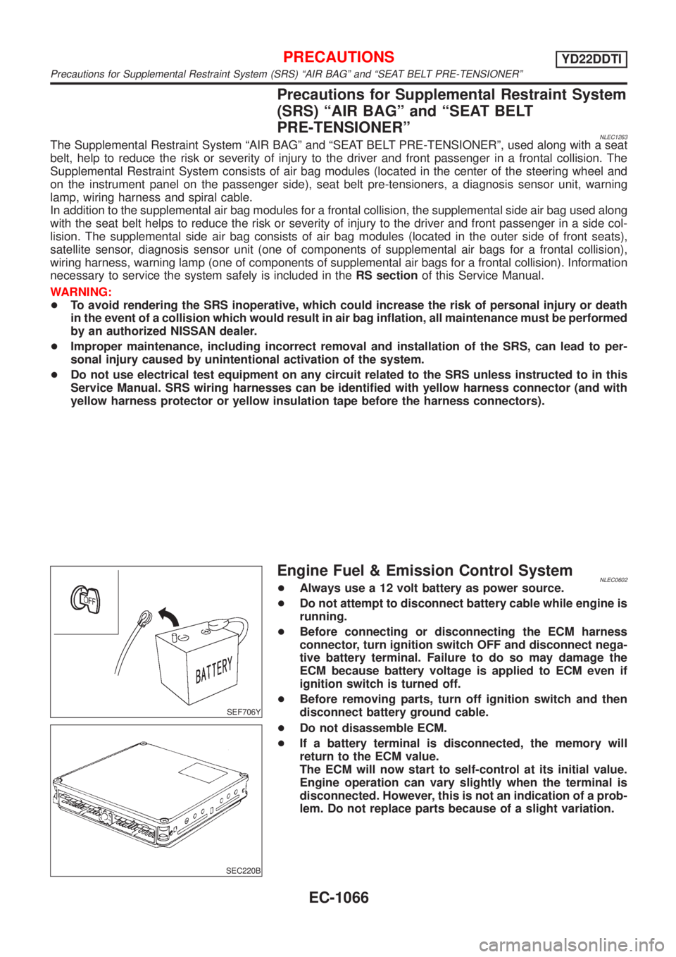
SEF706Y
Engine Fuel & Emission Control SystemNLEC0602+Always use a 12 volt battery as power source.
+Do not attempt to disconnect battery cable while engine is
running.
+Before connecting or disconnecting the ECM harness
connector, turn ignition switch OFF and disconnect nega-
tive battery terminal. Failure to do so may damage the
ECM because battery voltage is applied to ECM even if
ignition switch is turned off.
+Before removing parts, turn off ignition switch and then
disconnect battery ground cable.
SEC220B
+Do not disassemble ECM.
+If a battery terminal is disconnected, the memory will
return to the ECM value.
The ECM will now start to self-control at its initial value.
Engine operation can vary slightly when the terminal is
disconnected. However, this is not an indication of a prob-
lem. Do not replace parts because of a slight variation.
PRECAUTIONSYD22DDTI
Precautions for Supplemental Restraint System (SRS) ªAIR BAGº and ªSEAT BELT PRE-TENSIONERº
EC-1066
Page 1513 of 3051
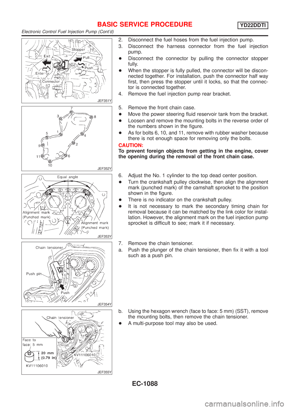
JEF351Y
2. Disconnect the fuel hoses from the fuel injection pump.
3. Disconnect the harness connector from the fuel injection
pump.
+Disconnect the connector by pulling the connector stopper
fully.
+When the stopper is fully pulled, the connector will be discon-
nected together. For installation, push the connector half way
first, then press the stopper until it locks, so that the connec-
tor is connected together.
4. Remove the fuel injection pump rear bracket.
JEF352Y
5. Remove the front chain case.
+Move the power steering fluid reservoir tank from the bracket.
+Loosen and remove the mounting bolts in the reverse order of
the numbers shown in the figure.
+As for bolts 6, 10, and 11, remove with rubber washer because
there is not enough space for removing only the bolts.
CAUTION:
To prevent foreign objects from getting in the engine, cover
the opening during the removal of the front chain case.
JEF353Y
6. Adjust the No. 1 cylinder to the top dead center position.
+Turn the crankshaft pulley clockwise, then align the alignment
mark (punched mark) of the camshaft sprocket to the position
shown in the figure.
+There is no indicator on the crankshaft pulley.
+It is not necessary to mark the secondary timing chain for
removal because it can be matched by the link color for instal-
lation. However, the alignment mark on the fuel injection pump
sprocket is difficult to see; mark it if necessary.
JEF354Y
7. Remove the chain tensioner.
a. Push the plunger of the chain tensioner, then fix it with a tool
such as a push pin.
JEF355Y
b. Using the hexagon wrench (face to face: 5 mm) (SST), remove
the mounting bolts, then remove the chain tensioner.
+A multi-purpose tool may also be used.
BASIC SERVICE PROCEDUREYD22DDTI
Electronic Control Fuel Injection Pump (Cont'd)
EC-1088
Page 1732 of 3051
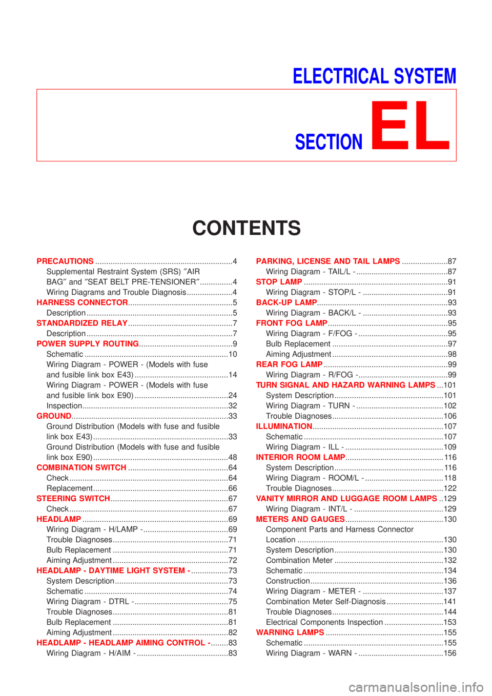
ELECTRICAL SYSTEM
SECTION
EL
CONTENTS
PRECAUTIONS...............................................................4
Supplemental Restraint System (SRS)²AIR
BAG²and²SEAT BELT PRE-TENSIONER²...............4
Wiring Diagrams and Trouble Diagnosis .....................4
HARNESS CONNECTOR................................................5
Description ...................................................................5
STANDARDIZED RELAY................................................7
Description ...................................................................7
POWER SUPPLY ROUTING...........................................9
Schematic ..................................................................10
Wiring Diagram - POWER - (Models with fuse
and fusible link box E43) ...........................................14
Wiring Diagram - POWER - (Models with fuse
and fusible link box E90) ...........................................24
Inspection...................................................................32
GROUND........................................................................33
Ground Distribution (Models with fuse and fusible
link box E43) ..............................................................33
Ground Distribution (Models with fuse and fusible
link box E90) ..............................................................48
COMBINATION SWITCH..............................................64
Check .........................................................................64
Replacement ..............................................................66
STEERING SWITCH......................................................67
Check .........................................................................67
HEADLAMP...................................................................69
Wiring Diagram - H/LAMP -.......................................69
Trouble Diagnoses.....................................................71
Bulb Replacement .....................................................71
Aiming Adjustment .....................................................72
HEADLAMP - DAYTIME LIGHT SYSTEM -.................73
System Description ....................................................73
Schematic ..................................................................74
Wiring Diagram - DTRL - ...........................................75
Trouble Diagnoses.....................................................81
Bulb Replacement .....................................................81
Aiming Adjustment .....................................................82
HEADLAMP - HEADLAMP AIMING CONTROL -........83
Wiring Diagram - H/AIM - ..........................................83PARKING, LICENSE AND TAIL LAMPS.....................87
Wiring Diagram - TAIL/L - ..........................................87
STOP LAMP..................................................................91
Wiring Diagram - STOP/L - .......................................91
BACK-UP LAMP............................................................93
Wiring Diagram - BACK/L - .......................................93
FRONT FOG LAMP.......................................................95
Wiring Diagram - F/FOG - .........................................95
Bulb Replacement .....................................................97
Aiming Adjustment .....................................................98
REAR FOG LAMP.........................................................99
Wiring Diagram - R/FOG -.........................................99
TURN SIGNAL AND HAZARD WARNING LAMPS...101
System Description ..................................................101
Wiring Diagram - TURN - ........................................102
Trouble Diagnoses...................................................106
ILLUMINATION............................................................107
Schematic ................................................................107
Wiring Diagram - ILL - .............................................109
INTERIOR ROOM LAMP............................................. 116
System Description .................................................. 116
Wiring Diagram - ROOM/L - .................................... 118
Trouble Diagnoses...................................................122
VANITY MIRROR AND LUGGAGE ROOM LAMPS..129
Wiring Diagram - INT/L - .........................................129
METERS AND GAUGES.............................................130
Component Parts and Harness Connector
Location ...................................................................130
System Description ..................................................130
Combination Meter ..................................................132
Schematic ................................................................134
Construction .............................................................136
Wiring Diagram - METER - .....................................137
Combination Meter Self-Diagnosis ..........................141
Trouble Diagnoses...................................................144
Electrical Components Inspection ...........................153
WARNING LAMPS......................................................155
Schematic ................................................................155
Wiring Diagram - WARN - .......................................156
Page 2257 of 3051
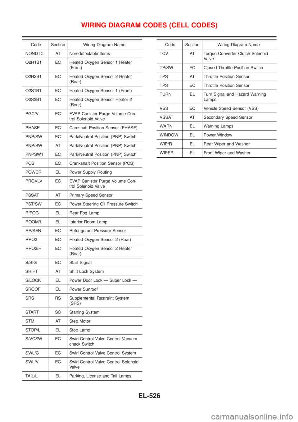
Code Section Wiring Diagram Name
NONDTC AT Non-detectable Items
O2H1B1 EC Heated Oxygen Sensor 1 Heater
(Front)
O2H2B1 EC Heated Oxygen Sensor 2 Heater
(Rear)
O2S1B1 EC Heated Oxygen Sensor 1 (Front)
O2S2B1 EC Heated Oxygen Sensor Heater 2
(Rear)
PGC/V EC EVAP Canister Purge Volume Con-
trol Solenoid Valve
PHASE EC Camshaft Position Sensor (PHASE)
PNP/SW EC Park/Neutral Position (PNP) Switch
PNP/SW AT Park/Neutral Position (PNP) Switch
PNPSW1 EC Park/Neutral Position (PNP) Switch
POS EC Crankshaft Position Sensor (POS)
POWER EL Power Supply Routing
PRGVLV EC EVAP Canister Purge Volume Con-
trol Solenoid Valve
PSSAT AT Primary Speed Sensor
PST/SW EC Power Steering Oil Pressure Switch
R/FOG EL Rear Fog Lamp
ROOM/L EL Interior Room Lamp
RP/SEN EC Referigerant Pressure Sensor
RRO2 EC Heated Oxygen Sensor 2 (Rear)
RRO2/H EC Heated Oxygen Sensor 2 Heater
(Rear)
S/SIG EC Start Signal
SHIFT AT Shift Lock System
S/LOCK EL Power Door Lock Ð Super Lock Ð
SROOF EL Power Sunroof
SRS RS Supplemental Restraint System
(SRS)
START SC Starting System
STM AT Step Motor
STOP/L EL Stop Lamp
S/VCSW EC Swirl Control Valve Control Vacuum
check Switch
SWL/C EC Swirl Control Valve Control System
SWL/V EC Swirl Control Valve Control Solenoid
Valve
TAIL/L EL Parking, License and Tail LampsCode Section Wiring Diagram Name
TCV AT Torque Converter Clutch Solenoid
Valve
TP/SW EC Closed Throttle Position Switch
TPS AT Throttle Position Sensor
TPS EC Throttle Position Sensor
TURN EL Turn Signal and Hazard Warning
Lamps
VSS EC Vehicle Speed Sensor (VSS)
VSSAT AT Secondary Speed Sensor
WARN EL Warning Lamps
WINDOW EL Power Window
WIP/R EL Rear Wiper and Washer
WIPER EL Front Wiper and Washer
WIRING DIAGRAM CODES (CELL CODES)
EL-526
Page 2274 of 3051
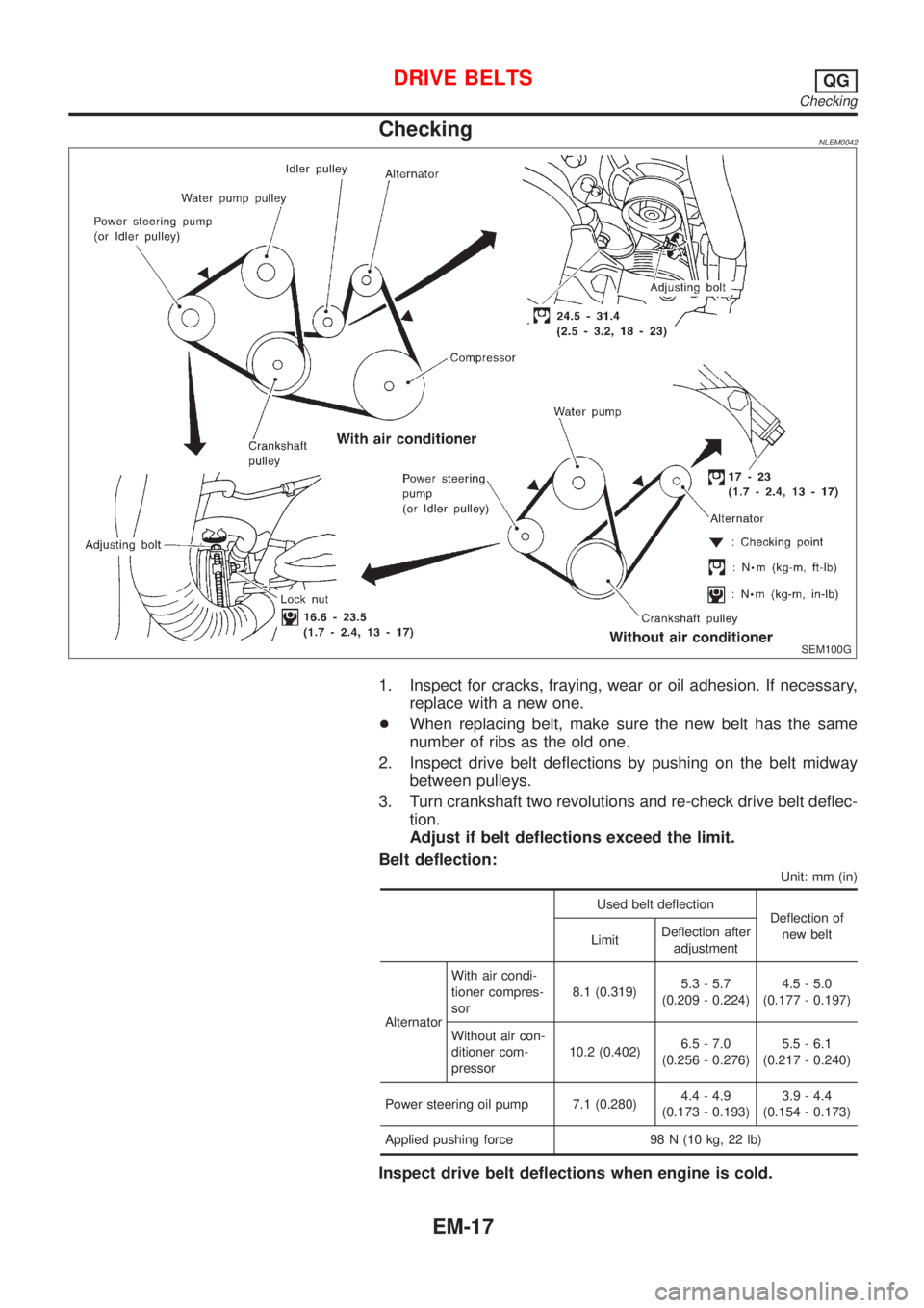
CheckingNLEM0042
SEM100G
1. Inspect for cracks, fraying, wear or oil adhesion. If necessary,
replace with a new one.
+When replacing belt, make sure the new belt has the same
number of ribs as the old one.
2. Inspect drive belt deflections by pushing on the belt midway
between pulleys.
3. Turn crankshaft two revolutions and re-check drive belt deflec-
tion.
Adjust if belt deflections exceed the limit.
Belt deflection:
Unit: mm (in)
Used belt deflection
Deflection of
new belt
LimitDeflection after
adjustment
AlternatorWith air condi-
tioner compres-
sor8.1 (0.319)5.3 - 5.7
(0.209 - 0.224)4.5 - 5.0
(0.177 - 0.197)
Without air con-
ditioner com-
pressor10.2 (0.402)6.5 - 7.0
(0.256 - 0.276)5.5 - 6.1
(0.217 - 0.240)
Power steering oil pump 7.1 (0.280)4.4 - 4.9
(0.173 - 0.193)3.9 - 4.4
(0.154 - 0.173)
Applied pushing force 98 N (10 kg, 22 lb)
Inspect drive belt deflections when engine is cold.
DRIVE BELTSQG
Checking
EM-17
Page 2280 of 3051
CAUTION:
+After removing timing chain, do not turn crankshaft and
camshaft separately, or valves will strike piston heads.
+When installing chain tensioner, oil seals, or other sliding
parts, lubricate contacting surfaces with new engine oil.
+Apply new engine oil to bolt threads and seat surfaces
when installing camshaft sprocket and crankshaft pulley.
+When removing oil pump assembly, remove camshaft
position sensor (PHASE), then remove timing chain from
engine.
+Be careful not to damage sensor edges.
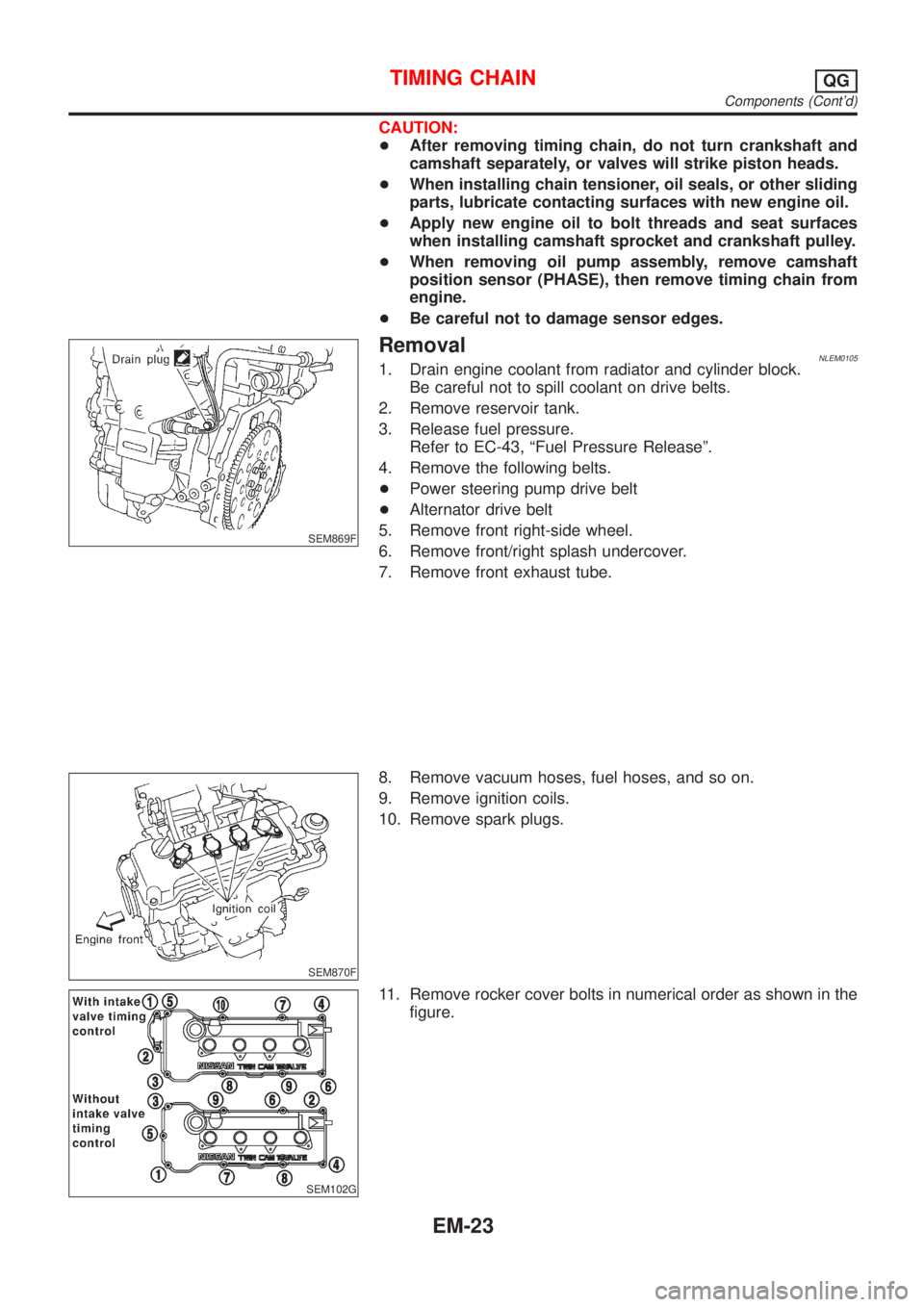
SEM869F
RemovalNLEM01051. Drain engine coolant from radiator and cylinder block.
Be careful not to spill coolant on drive belts.
2. Remove reservoir tank.
3. Release fuel pressure.
Refer to EC-43, ªFuel Pressure Releaseº.
4. Remove the following belts.
+Power steering pump drive belt
+Alternator drive belt
5. Remove front right-side wheel.
6. Remove front/right splash undercover.
7. Remove front exhaust tube.
SEM870F
8. Remove vacuum hoses, fuel hoses, and so on.
9. Remove ignition coils.
10. Remove spark plugs.
SEM102G
11. Remove rocker cover bolts in numerical order as shown in the
figure.
TIMING CHAINQG
Components (Cont'd)
EM-23