Page 2283 of 3051
SEM104G
27. Remove RH engine mounting bracket.
28. Remove idler pulley and bracket.
SEM883F
29. Remove water pump pulley and water pump.
30. Remove front cover bolts and front cover as shown.
H1: Located on water pump
H2: Located on power steering pump adjusting bar
+Inspect for oil leakage at front oil seal. Replace seal if oil leak
is present.
SEM884F
SEM897F
31. Remove timing chain.
32. Remove oil pump drive spacer.
33. Remove chain guides.
34. Remove crankshaft sprocket.
35. Remove O-rings from cylinder block and front cover.
SEM885F
InspectionNLEM0106Check for cracks and excessive wear at roller links. Replace
if necessary.
TIMING CHAINQG
Removal (Cont'd)
EM-26
Page 2288 of 3051
SEM909F
ReplacementNLEM0015VALVE OIL SEALNLEM0015S011. Remove rocker cover.
2. Remove camshaft.
3. Remove valve spring. Refer to EM-36.
4. Remove valve oil seal with Tool.
Piston concerned should be set at TDC to prevent valve from
falling.
SEM910F
5. Apply new engine oil to new valve oil seal and install it with
Tool.
SEM911F
FRONT OIL SEALNLEM0015S021. Remove the following parts:
+Engine under cover
+RH engine side cover
+Alternator and power steering drive belts
+Crankshaft pulley
2. Remove front oil seal from front cover.
+Be careful not to scratch front cover.
SEM715A
SEM912F
3. Apply new engine oil to new oil seal and install it using a suit-
able tool.
+Install new oil seal in the direction shown.
OIL SEALQG
Replacement
EM-31
Page 2307 of 3051

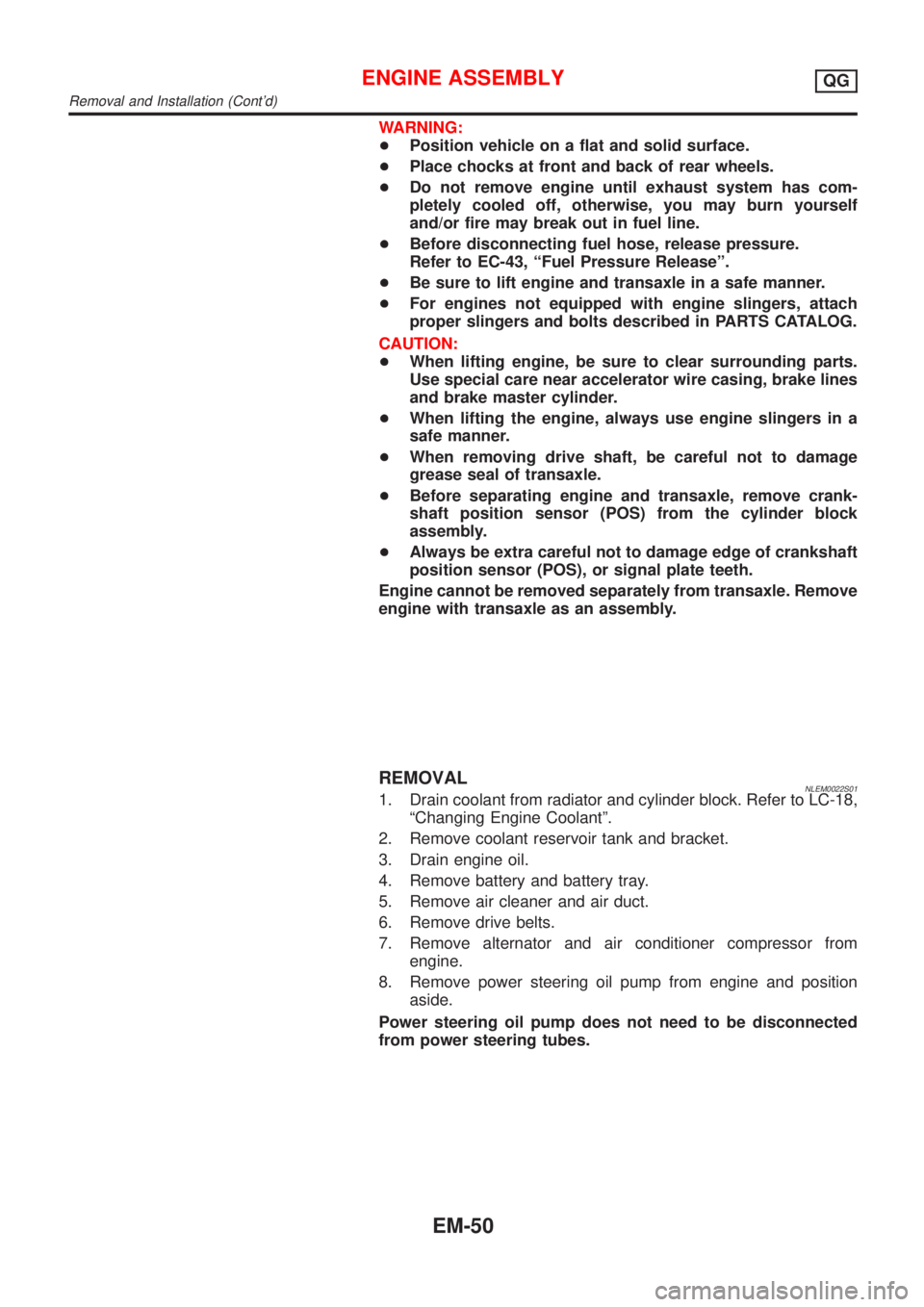
WARNING:
+Position vehicle on a flat and solid surface.
+Place chocks at front and back of rear wheels.
+Do not remove engine until exhaust system has com-
pletely cooled off, otherwise, you may burn yourself
and/or fire may break out in fuel line.
+Before disconnecting fuel hose, release pressure.
Refer to EC-43, ªFuel Pressure Releaseº.
+Be sure to lift engine and transaxle in a safe manner.
+For engines not equipped with engine slingers, attach
proper slingers and bolts described in PARTS CATALOG.
CAUTION:
+When lifting engine, be sure to clear surrounding parts.
Use special care near accelerator wire casing, brake lines
and brake master cylinder.
+When lifting the engine, always use engine slingers in a
safe manner.
+When removing drive shaft, be careful not to damage
grease seal of transaxle.
+Before separating engine and transaxle, remove crank-
shaft position sensor (POS) from the cylinder block
assembly.
+Always be extra careful not to damage edge of crankshaft
position sensor (POS), or signal plate teeth.
Engine cannot be removed separately from transaxle. Remove
engine with transaxle as an assembly.
REMOVALNLEM0022S011. Drain coolant from radiator and cylinder block. Refer to LC-18,
ªChanging Engine Coolantº.
2. Remove coolant reservoir tank and bracket.
3. Drain engine oil.
4. Remove battery and battery tray.
5. Remove air cleaner and air duct.
6. Remove drive belts.
7. Remove alternator and air conditioner compressor from
engine.
8. Remove power steering oil pump from engine and position
aside.
Power steering oil pump does not need to be disconnected
from power steering tubes.
ENGINE ASSEMBLYQG
Removal and Installation (Cont'd)
EM-50
Page 2321 of 3051

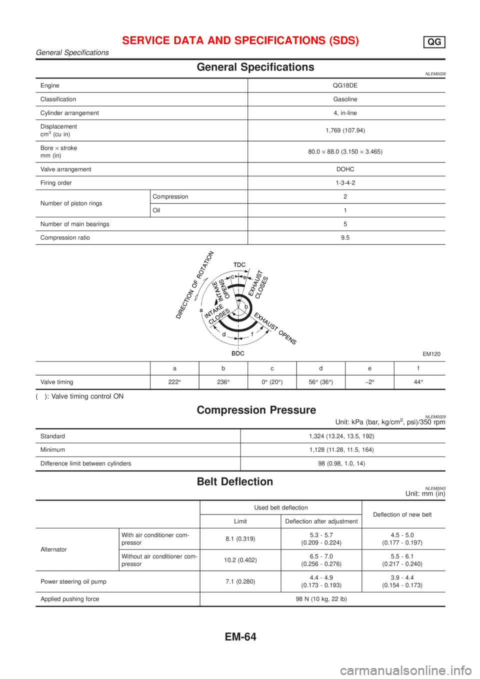
General SpecificationsNLEM0028
EngineQG18DE
ClassificationGasoline
Cylinder arrangement4, in-line
Displacement
cm
3(cu in)1,769 (107.94)
Bore´stroke
mm (in)80.0´88.0 (3.150´3.465)
Valve arrangementDOHC
Firing order1-3-4-2
Number of piston ringsCompression 2
Oil 1
Number of main bearings5
Compression ratio9.5
EM120
abcde f
Valve timing 222É 236É 0É (20É) 56É (36É) þ2É 44É
( ): Valve timing control ON
Compression PressureNLEM0029Unit: kPa (bar, kg/cm2, psi)/350 rpm
Standard1,324 (13.24, 13.5, 192)
Minimum1,128 (11.28, 11.5, 164)
Difference limit between cylinders 98 (0.98, 1.0, 14)
Belt DeflectionNLEM0045Unit: mm (in)
Used belt deflection
Deflection of new belt
Limit Deflection after adjustment
AlternatorWith air conditioner com-
pressor8.1 (0.319)5.3 - 5.7
(0.209 - 0.224)4.5 - 5.0
(0.177 - 0.197)
Without air conditioner com-
pressor10.2 (0.402)6.5 - 7.0
(0.256 - 0.276)5.5 - 6.1
(0.217 - 0.240)
Power steering oil pump 7.1 (0.280)4.4 - 4.9
(0.173 - 0.193)3.9 - 4.4
(0.154 - 0.173)
Applied pushing force98 N (10 kg, 22 lb)
SERVICE DATA AND SPECIFICATIONS (SDS)QG
General Specifications
EM-64
Page 2339 of 3051
Removal and InstallationNLEM0117
NEM351
1. Oil filler cap
2. Rocker cover
3. PCV valve
4. Distributor
5. Intake manifold supports6. Knock sensor
7. Oil filter
8. Oil filter bracket
9. Water inlet
10. Thermostat housing11. Water pipe assembly
12. Thermostat
13. Starter motor
14. Power steering oil pump adjusting
bar
15. Power steering oil pump bracket
OUTER COMPONENT PARTSSR
Removal and Installation
EM-82
Page 2344 of 3051

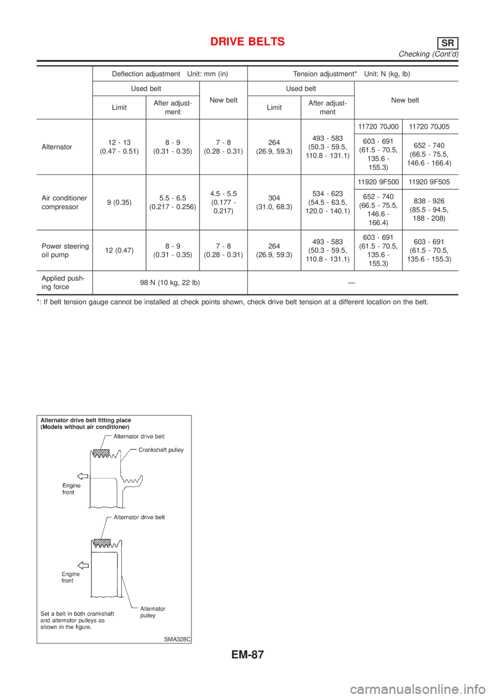
Deflection adjustment Unit: mm (in) Tension adjustment* Unit: N (kg, lb)
Used belt
New beltUsed belt
New belt
LimitAfter adjust-
mentLimitAfter adjust-
ment
Alternator12-13
(0.47 - 0.51)8-9
(0.31 - 0.35)7-8
(0.28 - 0.31)264
(26.9, 59.3)493 - 583
(50.3 - 59.5,
110.8 - 131.1)11720 70J00 11720 70J05
603 - 691
(61.5 - 70.5,
135.6 -
155.3)652 - 740
(66.5 - 75.5,
146.6 - 166.4)
Air conditioner
compressor9 (0.35)5.5 - 6.5
(0.217 - 0.256)4.5 - 5.5
(0.177 -
0.217)304
(31.0, 68.3)534 - 623
(54.5 - 63.5,
120.0 - 140.1)11920 9F500 11920 9F505
652 - 740
(66.5 - 75.5,
146.6 -
166.4)838 - 926
(85.5 - 94.5,
188 - 208)
Power steering
oil pump12 (0.47)8-9
(0.31 - 0.35)7-8
(0.28 - 0.31)264
(26.9, 59.3)493 - 583
(50.3 - 59.5,
110.8 - 131.1)603 - 691
(61.5 - 70.5,
135.6 -
155.3)603 - 691
(61.5 - 70.5,
135.6 - 155.3)
Applied push-
ing force98 N (10 kg, 22 lb) Ð
*: If belt tension gauge cannot be installed at check points shown, check drive belt tension at a different location on the belt.
SMA328C
DRIVE BELTSSR
Checking (Cont'd)
EM-87
Page 2388 of 3051

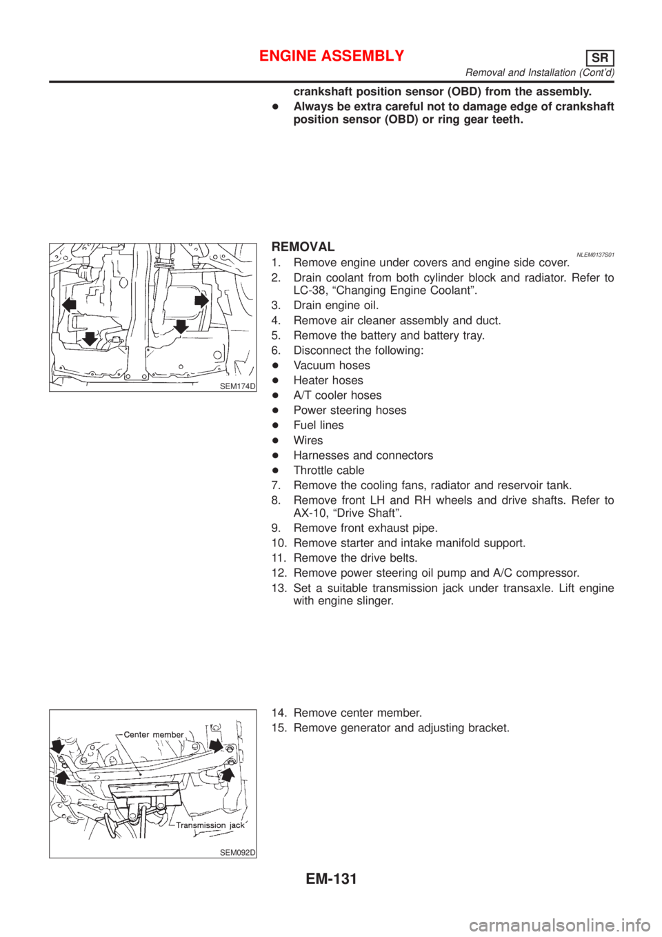
crankshaft position sensor (OBD) from the assembly.
+Always be extra careful not to damage edge of crankshaft
position sensor (OBD) or ring gear teeth.
SEM174D
REMOVALNLEM0137S011. Remove engine under covers and engine side cover.
2. Drain coolant from both cylinder block and radiator. Refer to
LC-38, ªChanging Engine Coolantº.
3. Drain engine oil.
4. Remove air cleaner assembly and duct.
5. Remove the battery and battery tray.
6. Disconnect the following:
+Vacuum hoses
+Heater hoses
+A/T cooler hoses
+Power steering hoses
+Fuel lines
+Wires
+Harnesses and connectors
+Throttle cable
7. Remove the cooling fans, radiator and reservoir tank.
8. Remove front LH and RH wheels and drive shafts. Refer to
AX-10, ªDrive Shaftº.
9. Remove front exhaust pipe.
10. Remove starter and intake manifold support.
11. Remove the drive belts.
12. Remove power steering oil pump and A/C compressor.
13. Set a suitable transmission jack under transaxle. Lift engine
with engine slinger.
SEM092D
14. Remove center member.
15. Remove generator and adjusting bracket.
ENGINE ASSEMBLYSR
Removal and Installation (Cont'd)
EM-131
Page 2390 of 3051
ComponentsNLEM0138
NEM350
1. Rear oil seal retainer
2. Cylinder block
3. Water pump
4. Power steering oil pump adjusting
bar
5. Front cover with oil pump
6. Oil strainer
7. Thrust bearing
8. Crankshaft9. Connecting rod bushing
10. Piston rings
11. Piston
12. Piston pin
13. Connecting rod
14. Connecting rod bearing
15. Aluminum oil pan
16. Rear cover plate
17. Oil pan drain plug18. Steel oil pan
19. Baffle plate
20. Main bearing cap
21. Pilot converter
22. Drive plate
23. Reinforcement plate
24. Rear plate
25. Main bearing
CYLINDER BLOCKSR
Components
EM-133