2001 NISSAN ALMERA TINO brake sensor
[x] Cancel search: brake sensorPage 2307 of 3051
WARNING:
+Position vehicle on a flat and solid surface.
+Place chocks at front and back of rear wheels.
+Do not remove engine until exhaust system has com-
pletely cooled off, otherwise, you may burn yourself
and/or fire may break out in fuel line.
+Before disconnecting fuel hose, release pressure.
Refer to EC-43, ªFuel Pressure Releaseº.
+Be sure to lift engine and transaxle in a safe manner.
+For engines not equipped with engine slingers, attach
proper slingers and bolts described in PARTS CATALOG.
CAUTION:
+When lifting engine, be sure to clear surrounding parts.
Use special care near accelerator wire casing, brake lines
and brake master cylinder.
+When lifting the engine, always use engine slingers in a
safe manner.
+When removing drive shaft, be careful not to damage
grease seal of transaxle.
+Before separating engine and transaxle, remove crank-
shaft position sensor (POS) from the cylinder block
assembly.
+Always be extra careful not to damage edge of crankshaft
position sensor (POS), or signal plate teeth.
Engine cannot be removed separately from transaxle. Remove
engine with transaxle as an assembly.
REMOVALNLEM0022S011. Drain coolant from radiator and cylinder block. Refer to LC-18,
ªChanging Engine Coolantº.
2. Remove coolant reservoir tank and bracket.
3. Drain engine oil.
4. Remove battery and battery tray.
5. Remove air cleaner and air duct.
6. Remove drive belts.
7. Remove alternator and air conditioner compressor from
engine.
8. Remove power steering oil pump from engine and position
aside.
Power steering oil pump does not need to be disconnected
from power steering tubes.
ENGINE ASSEMBLYQG
Removal and Installation (Cont'd)
EM-50
Page 2476 of 3051
crankshaft position sensor (TDC sensor) from the assem-
bly.
+Always pay extra attention not to damage edge of crank-
shaft position sensor (TDC sensor) or ring gear teeth.
REMOVALNLEM0069S011. Remove engine undercover, and hood for hoisting.
2. Drain coolant from both cylinder block and radiator. Refer to
LC-59, ªChanging Engine Coolantº.
3. Remove the following parts:
+Battery
+RH and LH front wheels
+RH and LH splash covers (combined with undercover)
+Auxiliary belts
+Alternator
+Alternator brackets
+Radiator and cooling fan
+Engine cover
+Air ducts and air cleaner case
LH side of engine room:
4. Disconnect all harnesses and grounds that are connected to
components on vehicle.
5. Disconnect vacuum hose on vacuum pump side.
6. Disconnect fuel feed and fuel return hoses on engine side.
+Immediately put blind plugs into the openings to prevent
fuel from flowing out.
7. Disconnect heater hose. Plug opening of hose to prevent cool-
ant from flowing out.
RH side of engine room:
8. Remove air conditioner compressor from brackets and move
it toward vehicle side. Secure compressor on vehicle side with
rope.
Vehicle underside:
9. Remove exhaust front tube.
10. Disconnect two hoses from power steering pump and plug to
stop fluid.
11. Remove M/T control rod and support rod.
12. Remove ABS wheel sensor, and temporarily hang brake cali-
per with rope on vehicle side.
13. Remove RH and LH drive shafts.
SEM499G
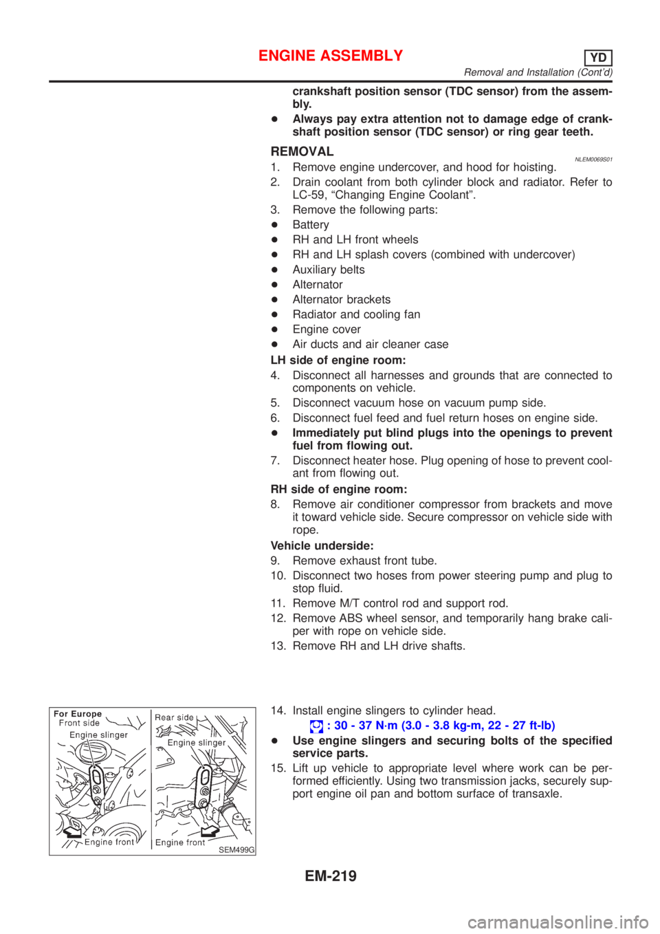
14. Install engine slingers to cylinder head.
: 30 - 37 N´m (3.0 - 3.8 kg-m, 22 - 27 ft-lb)
+Use engine slingers and securing bolts of the specified
service parts.
15. Lift up vehicle to appropriate level where work can be per-
formed efficiently. Using two transmission jacks, securely sup-
port engine oil pan and bottom surface of transaxle.
ENGINE ASSEMBLYYD
Removal and Installation (Cont'd)
EM-219
Page 2697 of 3051
A
A/C HFC134a (R134a) system precaution . HA-2
A/C HFC134a (R134a) system service
procedure .............................................. HA-85
A/C HFC134a (R134a) system service
tools ....................................................... HA-10
A/C HFC134a system service equip-
ment precaution ....................................... HA-6
A/C air flow ............................................... HA-19
A/C component layout .............................. HA-17
A/C compressor clutch removal and
installation .............................................. HA-90
A/C compressor precaution ........................ HA-5
A/C compressor special service tool .......... HA-9
A/C control linkage adjustment
(manual A/C) ......................................... HA-48
A/C control operation (manual A/C) .......... HA-18
A/C diagnostic work flow (manual
A/C) ...................................................... HA-40
A/C harness layout (manual A/C) ............. HA-21
A/C lubricant (R134a) ............................... HA-87
A/C operational check ............................... HA-41
A/C performance chart .............................. HA-78
A/C performance test diagnoses .............. HA-76
A/C relay ................................................... HA-73
A/C service data specification ................ HA-104
A/C switch ................................................. HA-74
A/C, M - Wiring diagram ........................... HA-27
A/CCUT - Wiring diagram ..................... EC-1301
A/T - Wiring diagram - AT - BA/FTS ........ AT-172
A/T - Wiring diagram - AT - ENG SS ........ AT-91,
177
A/T - Wiring diagram - AT - FTS ................ AT-75
A/T - Wiring diagram - AT - LPSV ... AT-101, 159
A/T - Wiring diagram - AT - MAIN ............. AT-62
A/T - Wiring diagram - AT - PNP/SW ........ AT-68
A/T - Wiring diagram - AT - SSV/A .......... AT-147
A/T - Wiring diagram - AT - TCV ....... AT-96, 166
A/T - Wiring diagram - AT - TPS ..... AT-106, 139
A/T - Wiring diagram - AT - VSS/AT .. AT-86, 128
A/T - Wiring diagram - AT -
VSSMTR .............................................. AT-134
A/T control ............................................. EC-1012
A/T diagnosis communication line .......... EC-928
A/T shift lock system - Wiring
diagram ................................................ AT-196
A/T shift lock system ................................ AT-195
A/T trouble diagnoses .......................... AT-41, 46
AAC/V - Wiring diagram . EC-345, 468, 865, 997
ABS (anti-lock brake system) ................... BR-42
ABS - Wiring diagram ............................... BR-48
ABS sensor rotor ....................................... AX-23
APS - Wiring diagram ........................... EC-1155
AT/C - Wiring diagram .......................... EC-1013
ATDIAG - Wiring diagram ....................... EC-929
Accelerator control system .................... FE-3, 14
Accelerator position sensor ................... EC-1155
Air bag disposal ........................................ RS-30Air bag precautions .................................. GI-3
Air bag ....................................................... RS-16
Air bleeding (hydraulic clutch) ................... CL-10
Air bleeding for brake system ..................... BR-8
Air conditioner cut control ....... EC-38, 572, 1081
Air flow meter - See Mass air flow
sensor ................................ EC-154, 679, 1143
Air mix door control linkage
adjustment ............................................. HA-50
Air spoiler, rear .......................................... BT-38
Alternator ................................................... SC-28
Angular tightening application ...... EM-5, 76, 158
Antenna - See Power antenna ................ EL-233
Anti-lock brake system - Wiring
diagram .................................................. BR-48
Audio and A/C control removal and
installation - See Instrument panel ........ BT-22
Audio ........................................................ EL-208
Automatic transaxle number ...................... GI-40
Auxiliary air control (AAC) valve .... EC-343, 466,
863, 995
B
Back-up lamp switch (M/T) ....................... MT-16
Back-up lamp ............................................. EL-93
Ball joint (front) .......................................... SU-13
Basic inspection ...................... EC-99, 623,1111
Battery ......................................................... SC-3
Baulk ring (M/T) .................................. MT-25, 63
Blower motor ............................................. HA-61
Blower resistor .......................................... HA-61
Board-on lift ................................................ GI-42
Body alignment .......................................... BT-65
Brake booster ............................................ BR-16
Brake fluid change ...................................... BR-7
Brake fluid level and line check .................. BR-7
Brake hydraulic line .................................... BR-9
Brake pedal ............................................... BR-11
Bulb specifications ................................... EL-524
Bumper, front .............................................. BT-7
Bumper, rear .............................................. BT-10
C
CHARGE - Wiring diagram ....................... SC-25
CHIME - Wiring diagram ......................... EL-166
CIGAR - Wiring diagram ......................... EL-195
CKPS - Wiring diagram . EC-297, 440, 821, 911,
970, 1166
CMPS - Wiring diagram .................. EC-304, 828
CONSULT for ABS .................................... BR-58
CONSULT for engine .............. EC-82, 607, 1102
COOL/F - Wiring diagram ..... EC-376, 885, 1201
Camshaft inspection ................. EM-36, 114, 204
Camshaft position sensor (CMPS) . EC-302, 825
Camshaft position sensor (PHASE) ........ EC-302
ALPHABETICAL INDEX
IDX-2
Page 2699 of 3051
Engine control component parts
location ................................ EC-26, 560, 1071
Engine control module (ECM) ........ EC-358, 880
Engine control system diagram and
chart .................................... EC-32, 566, 1076
Engine coolant temperature sensor
(ECTS) .............................. EC-169, 694, 1150
Engine fail-safe system .................. EC-123, 647
Engine oil precautions .................................. GI-7
Engine outer component parts ........... EM-12, 82
Engine removal ........................ EM-49, 130, 218
Engine room - See Engine
compartment .......................................... BT-66
Engine serial number ................................. GI-39
Evaporative emission (EVAP)
system ........................................... EC-39, 573
Exhaust gas recirculation (EGR)
valve ........... EC-310, 393, 446, 834, 921, 975
Exhaust system ................................... FE-11, 23
Exterior ...................................................... BT-38
F
F/PUMP - Wiring diagram ............. EC-518, 1034
FR02 - Wiring diagram .. EC-187, 207, 216, 415,
712, 732, 741, 945
FR02/H - Wiring diagram ............... EC-223, 422,
748, 952
FUEL - Wiring diagram ... EC-271, 279, 794, 802
Fan switch ................................................. HA-61
Final drive (FF M/T) ...................... MT-47, 63, 77
Finisher, interior - See Trim ....................... BT-28
Finisher, trunk lid ....................................... BT-31
Floor trim ................................................... BT-28
Fluids ........................................................ MA-20
Flywheel (clutch) ....................................... CL-22
Flywheel runout ........................ EM-60, 142, 235
Fog lamp, front, removal and
installation ................................................ BT-7
Fog lamp, front .......................................... EL-95
Fork rod (M/T) ..................................... MT-26, 64
Freeze frame data .............. EC-61, 71, 585, 596
Front axle .................................................... AX-2
Front bumper ............................................... BT-7
Front combination lamp removal and
installation ................................................ BT-7
Front disc brake ........................................ BR-24
Front door .................................................. BT-13
Front fog lamp removal and
installation ................................................ BT-7
Front fog lamp ........................................... EL-95
Front heated oxygen sensor (HO2S)
heater .......................... EC-221, 421, 746, 951
Front heated oxygen sensor (HO2S) ..... EC-184,
192, 198, 204, 214, 414, 709,
717, 723, 729, 739, 944Front seat belt ............................................. RS-5
Front seat .................................................. BT-46
Front suspension ........................................ SU-2
Front washer ............................................ EL-176
Front wiper ............................................... EL-176
Fuel cut control (at no load & high
engine speed) ..................... EC-39, 573, 1081
Fuel gauge ............................................... EL-130
Fuel injection system ............. EC-269, 277, 792,
800, 1079
Fuel injector .................................. EC-494, 1021
Fuel precautions ........................................... GI-8
Fuel pressure check ......................... EC-43, 577
Fuel pressure regulator .................... EC-44, 578
Fuel pressure release ....................... EC-43, 577
Fuel pump relay ............................ EC-516, 1032
Fuel pump ..................................... EC-516, 1032
Fuel system ........................................... FE-5, 15
Fuel tank vacuum relief valve ........... EC-40, 574
Fuse block ............................................... EL-527
Fuse ........................................................... EL-32
Fusible link ................................................. EL-32G
GLOW - Wiring diagram ....................... EC-1267
Garage jack and safety stand .................... GI-43
Gauges .................................................... EL-130
Gear components (M/T) ..................... MT-25, 63
Generator - See Alternator ....................... SC-28
Generic scan tool (GST) ................... EC-93, 617
Glass .......................................................... BT-14
Glow plug .............................................. EC-1267
Glow relay ............................................. EC-1267
Grease ...................................................... MA-20
Ground distribution .............................. EL-33, 48
H
H/LAMP - Wiring diagram .......................... EL-69
HEATER - Wiring diagram ........................ HA-23
HFC134a (R134a) system
precaution ................................................ HA-2
HFC134a (R134a) system service
procedure .............................................. HA-85
HFC134a (R134a) system service
tools ....................................................... HA-10
HFC134a system service equipment
precaution ................................................ HA-6
HORN - Wiring diagram .......................... EL-193
HSEAT - Wiring diagram ......................... EL-234
Harness connector ...................................... EL-5
Harness layout ......................................... EL-452
Hazard warning lamp .............................. EL-101
Headlamp removal and installation ............. BT-7
Headlamp washer .................................... EL-190
ALPHABETICAL INDEX
IDX-4
Page 2701 of 3051
N
NATS (Nissan Anti-theft System)
precautions ................................................... GI-3
NATS (Nissan Anti-theft System) ............ EL-334
NATS - Wiring diagram ............................ EL-338
NVH troubleshooting (AX) ........................... AX-3
NVH troubleshooting (BR) .......................... BR-6
NVH troubleshooting (MT) .......................... MT-9
NVH troubleshooting (ST) ........................... ST-5
NVH troubleshooting (SU) ........................ SU-17
NVH troubleshooting CL ............................. CL-4
NVIS (Nissan vehicle immobiliser sys-
tem) precautions ....................................... GI-3
Neutral position switch . EC-402, 490, 931, 1016
O
Oil pan (engine) ......................... EM-20, 91, 170
Oil pressure (engine) ...................... LC-5, 25, 44
Oil pump (engine) ........................... LC-5, 25, 44
Oil pump regulator valve (engine) .. LC-7, 27, 46
Oil seal replacement (engine) .......... EM-31, 105
On board diagnostic system ... EC-59, 583, 1096
Operating cylinder (clutch) ........................ CL-14
P
PCV (positive crankcase ventilation) ....... EC-42,
576, 1082
PGC/V - Wiring diagram . EC-334, 460, 854, 988
PNP/SW - Wiring diagram ..... EC-404, 491, 933,
1017, 1297
POWER - Wiring diagram ................... EL-14, 24
PST/SW - Wiring diagram ............ EC-524, 1040
Park/Neutral position switch .. EC-402, 490, 931,
1016, 1297
Park/neutral position switch (A/T) .............. AT-66
Park/neutral position switch (M/T) ............ MT-16
Parking brake control ................................ BR-40
Parking lamp .............................................. EL-87
Piston assembly ....................... EM-60, 142, 236
Piston pin inspection ................ EM-54, 134, 226
Piston ring inspection ............... EM-54, 135, 226
Piston to bore clearance .......... EM-56, 137, 228
Power antenna ........................................ EL-233
Power door lock ....................................... EL-257
Power door mirror .................................... EL-241
Power steering fluid level ............................ ST-7
Power steering gear .................................. ST-15
Power steering hydraulic pressure .............. ST-9
Power steering oil pressure switch ........ EC-523,
1039
Power steering oil pump ..................... ST-21, 22
Power steering system bleeding ................. ST-8
Power supply routing ................................... EL-9Power transistor ............................ EC-907, 1010
Power window ......................................... EL-245
Precautions (General) .................................. GI-4
Pressure plate - See Clutch cover ............ CL-22
Pressure test (A/T) ..................................... AT-52
Priming pump .............................. EC-1094,1111
Q
Quick-glow system ................................ EC-1267
R
RR02 - Wiring diagram .. EC-230, 240, 249, 258,
427, 755, 764, 773, 781, 957
RR02/H - Wiring diagram .............. EC-265, 434,
788, 964
Radiator fan - See Cooling fan ................. LC-37
Radiator ......................................... LC-17, 37, 58
Radio - See Audio ................................... EL-208
Rear air spoiler .......................................... BT-38
Rear axle (disc brake type) ....................... AX-23
Rear axle ................................................... AX-21
Rear bumper .............................................. BT-10
Rear combination lamp removal and
installation .............................................. BT-38
Rear disc brake .................................. BR-28, 36
Rear door ................................................... BT-13
Rear heated oxygen sensor (HO2S)
heater .......................... EC-263, 433, 786, 963
Rear heated oxygen sensor (HO2S) ..... EC-227,
237, 246, 256, 426, 752, 761, 770, 779, 956
Rear seat belt ............................................. RS-7
Rear seat ................................................... BT-49
Rear suspension ....................................... SU-17
Rear window defogger ............................ EL-198
Rear window .............................................. BT-59
Refrigerant connection precaution .............. HA-3
Refrigerant general precaution ................... HA-2
Refrigerant lines ........................................ HA-98
Refrigeration cycle .................................... HA-12
Release bearing (clutch) ..................... CL-17, 20
Removal and installation (A/T) ................ AT-206
Resistor ......................................... EC-908, 1011
Reverse idler shaft (M/T) .................... MT-24, 63
Reverse lamp switch (M/T) - See
Back-up lamp switch (M/T) ................... MT-16
Reverse main gear (M/T) .................... MT-25, 63
Revolution sensor (A/T) ....................... AT-83, 89
Road wheel size ......................................... GI-41
Roof trim .................................................... BT-35
Room lamp - See Interior lamp ............... EL-116
ALPHABETICAL INDEX
IDX-6
Page 2702 of 3051

S
S/LOCK - Wiring diagram ................ EL-260, 286
S/SIG - Wiring diagram ................. EC-512, 1028
SAE J1930 terminology list ........................ GI-48
SHIFT - Wiring diagram ........................... AT-196
SROOF - Wiring diagram ........................ EL-238
SRS - See Supplemental Restraint
System ................................................... RS-16
START - Wiring diagram ........................... SC-14
STOP/L - Wiring diagram .......................... EL-91
SWL/V - Wiring diagram ................. EC-366, 481
Seal - See Exterior .................................... BT-38
Seat belt pre-tensioner disposal ............... RS-30
Seat belt pre-tensioner ............................... RS-3
Seat belt, front ............................................ RS-5
Seat belt, rear ............................................. RS-7
Seat, front .................................................. BT-46
Seat, rear ................................................... BT-49
Self-diagnostic results ............ EC-73, 598, 1098
Shift control components (M/T) .......... MT-26, 64
Shift fork (M/T) .................................... MT-26, 64
Shift lever .................................................. MT-23
Shift lock system ...................................... AT-195
Shock absorber (front) .............................. SU-11
Shock absorber (rear) ............................... SU-23
Side air bag ............................................... RS-28
Side trim .................................................... BT-28
Speedometer ........................................... EL-130
Spiral cable ............................................... RS-24
Spring (Wheelarch) height .......................... SU-6
Stabilizer bar (front) .................................. SU-12
Stall test (A/T) ............................................ AT-51
Standardized relay ....................................... EL-7
Start signal .......................... EC-511, 1027, 1293
Starter ....................................................... SC-17
Starting system ......................................... SC-13
Steering linkage ......................................... ST-15
Steering switch .......................................... EL-67
Steering wheel and column ....................... ST-10
Steering wheel play ..................................... ST-6
Steering wheel turning force ....................... ST-8
Stop lamp .................................................. EL-91
Striking rod (M/T) ................................ MT-26, 64
Strut (front) ................................................ SU-10
Strut (rear) ................................................. SU-22
Sub-gear (M/T) .......................................... MT-25
Sunroof, electric ....................................... EL-238
Sunroof ...................................................... BT-51
Super lock ................................................ EL-281
Supplemental Restraint System ............... RS-16
Swirl control valve control solenoid
valve .................................. EC-366, 481, 1285
Symbols and abbreviations .......................... GI-9
Symptom matrix chart ........... EC-124, 648, 1116
Synchronizer (M/T) ............................. MT-25, 63
System readiness test (SRT) code ... EC-62, 586
T
TCM circuit diagram ................................... AT-13
TCM inspection table ................................. AT-58
TP/SW - Wiring diagram ................. EC-354, 874
TPS - Wiring diagram ..................... EC-178, 703
TURN - Wiring diagram ........................... EL-102
Tachometer .............................................. EL-130
Tail lamp .................................................... EL-87
Thermostat .................................... LC-15, 35, 57
Three way catalyst precautions ................... GI-6
Three way catalyst .......................... EC-327, 848
Throttle position sensor (TPS) ........ EC-175, 700
Throttle position sensor adjustment .. EC-99, 623
Throttle position switch ................... AT-111, 145,
EC-352, 872
Throwout bearing - See Clutch release
bearing ............................................. CL-17, 20
Tie-rod ball joints ....................................... ST-18
Tie-rod ........................................................ ST-15
Tightening torque of standard bolts ........... GI-47
Timing belt .......................................... EM-22, 96
Timing chain ........................................... EM-175
Tire size ...................................................... GI-41
Torque converter installation .................... AT-207
Tow truck towing ........................................ GI-45
Transmission case (M/T) .................... MT-24, 62
Tread-FR&RR (Dimensions) ...................... GI-41
Trim ............................................................ BT-28
Trouble diagnoses ...................................... GI-31
Trunk lid finisher ........................................ BT-31
Trunk lid opener - See Trunk lid ................ BT-10
Trunk lid trim .............................................. BT-31
Trunk lid ..................................................... BT-10
Trunk room trim ......................................... BT-31
Turn signal lamp ...................................... EL-101
Two trip detection logic ..................... EC-59, 583
Two-pole lift ................................................ GI-44
U
Under body ................................................ BT-68
V
VSS - Wiring diagram ........... EC-340, 860, 1172
Vacuum hose (brake system) ................... BR-18
Vacuum hose drawing (Engine control) ... EC-33,
567, 1077
Vacuum pump ........................................... BR-20
Valve clearance ................................ EM-42, 214
Valve guide ............................... EM-38, 116, 205
Valve lifter ................................................. EM-41
Valve seat ................................. EM-40, 117, 207
Valve spring .............................. EM-41, 119, 209
ALPHABETICAL INDEX
IDX-7
Page 3046 of 3051
SRA695A
SSU038
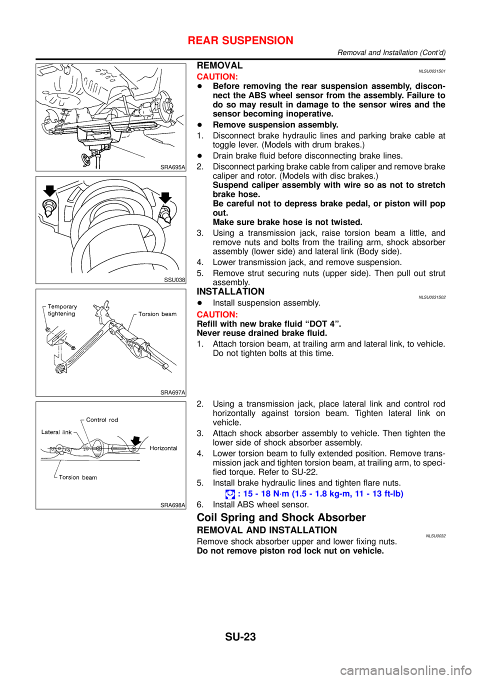
REMOVALNLSU0031S01CAUTION:
+Before removing the rear suspension assembly, discon-
nect the ABS wheel sensor from the assembly. Failure to
do so may result in damage to the sensor wires and the
sensor becoming inoperative.
+Remove suspension assembly.
1. Disconnect brake hydraulic lines and parking brake cable at
toggle lever. (Models with drum brakes.)
+Drain brake fluid before disconnecting brake lines.
2. Disconnect parking brake cable from caliper and remove brake
caliper and rotor. (Models with disc brakes.)
Suspend caliper assembly with wire so as not to stretch
brake hose.
Be careful not to depress brake pedal, or piston will pop
out.
Make sure brake hose is not twisted.
3. Using a transmission jack, raise torsion beam a little, and
remove nuts and bolts from the trailing arm, shock absorber
assembly (lower side) and lateral link (Body side).
4. Lower transmission jack, and remove suspension.
5. Remove strut securing nuts (upper side). Then pull out strut
assembly.
SRA697A
INSTALLATIONNLSU0031S02+Install suspension assembly.
CAUTION:
Refill with new brake fluid“DOT 4”.
Never reuse drained brake fluid.
1. Attach torsion beam, at trailing arm and lateral link, to vehicle.
Do not tighten bolts at this time.
SRA698A
2. Using a transmission jack, place lateral link and control rod
horizontally against torsion beam. Tighten lateral link on
vehicle.
3. Attach shock absorber assembly to vehicle. Then tighten the
lower side of shock absorber assembly.
4. Lower torsion beam to fully extended position. Remove trans-
mission jack and tighten torsion beam, at trailing arm, to speci-
fied torque. Refer to SU-22.
5. Install brake hydraulic lines and tighten flare nuts.
:15-18N·m (1.5 - 1.8 kg-m, 11 - 13 ft-lb)
6. Install ABS wheel sensor.
Coil Spring and Shock Absorber
REMOVAL AND INSTALLATIONNLSU0032Remove shock absorber upper and lower fixing nuts.
Do not remove piston rod lock nut on vehicle.
REAR SUSPENSION
Removal and Installation (Cont’d)
SU-23