2001 NISSAN ALMERA TINO warning
[x] Cancel search: warningPage 330 of 3051

General SpecificationsNLBR0077Unit: mm (in)
EngineQG18DE, SR20DE YD22DDTi
Front BrakeBrake model CL25VCG
Cylinder bore diameter 57.2 (2.2529)
Pad
Length×width×thickness110.6×54.2×11.0 (4.35×2.13×0.433)
Rotor outer
diameter×thickness280×28 (11.02×1.10)
Rear BrakeBrake model CL11HDG (disc brake)
Cylinder bore diam-
eterCam & Strut type 38 (1.496)
Ball & Ramp type 38.2 (1.504)
Pad
Length×width×thickness79.8×38.5×9.3 (3.142×1.516×0.37)
Rotor outer diameter×thickness 278×10 (10.94×0.39)
Master cylinder Cylinder bore diameter 23.81 (15/16)
Brake boosterBooster model S255 M215T S255
DiaphragmPrimary 255 (10.04) 230 (9.06) 255 (10.04)
Secondary—205 (8.07)—
Specified brake fluidDOT 4
Disc BrakeNLBR0078Unit: mm (in)
Brake modelCL25VCG CL11HDG
Pad wear limit Minimum thickness 2.0 (0.078) 2.0 (0.079)
Rotor repair limitMaximum runout 0.07 (0.0028) 0.07 (0.0028)
Minimum thickness 26.0 (1.024) 9 (0.35)
Brake PedalNLBR0079Unit: mm (in)
Free height“H”*LHDM/T 154.8 - 164.8 (6.09 - 6.49)
CVT 164 - 174 (6.46 - 6.85)
RHDM/T 154.8 - 164.8 (6.09 - 6.49)
CVT 164 - 174 (6.46 - 6.85)
Clearance“C”between pedal stopper and threaded end of stop lamp switch or brake switch 0.75 - 2.00 (0.0295 - 0.0787)
*: Measured from surface of dash panel to surface of pedal pad
Parking BrakeNLBR0080
TypeCenter lever
Number of notches
[under force of 196 N (20 kg, 44 lb)]5-6
Number of notches
when warning lamp switch comes on1
SERVICE DATA AND SPECIFICATIONS (SDS)
General Specifications
BR-93
Page 334 of 3051
Service NoticeNLBT0001+When removing or installing various parts, place a cloth or padding onto the vehicle body to prevent
scratches.
+Handle trim, molding, instruments, grille, etc. carefully during removing or installing. Be careful not to oil
or damage them.
+Apply sealing compound where necessary when installing parts.
+When applying sealing compound, be careful that the sealing compound does not protrude from parts.
+When replacing any metal parts (for example body outer panel, members, etc.), be sure to take rust pre-
vention measures.
Supplemental Restraint System (SRS) ªAIR
BAGº and ªSEAT BELT PRE-TENSIONERº
NLBT0002The Supplemental Restraint System such as ªAIR BAGº and ªSEAT BELT PRE-TENSIONERº used along with
a seat belt, helps to reduce the risk or severity of injury to the driver and front passenger for certain types of
collision. The SRS system composition which is available to NISSAN MODEL V10 is as follows (The compo-
sition varies according to the destination and optional equipment.):
+For a frontal collision
The Supplemental Restraint System consists of driver air bag module (located in the center of the steer-
ing wheel), front passenger air bag module (located on the instrument panel on passenger side), front seat
belt pre-tensioners, a diagnosis sensor unit, warning lamp, wiring harness and spiral cable.
+For a side collision
The Supplemental Restraint System consists of front side air bag module (located in the outer side of front
seat), side air bag (satellite) sensor, diagnosis sensor unit (one of components of air bags for a frontal
collision), wiring harness, warning lamp (one of components of air bags for a frontal collision).
Information necessary to service the system safely is included in theRS sectionof this Service Manual.
WARNING:
+To avoid rendering the SRS inoperative, which could increase the risk of personal injury or death
in the event of a collision which would result in air bag inflation, all maintenance should be per-
formed by an authorized NISSAN dealer.
+Improper maintenance, including incorrect removal and installation of the SRS, can lead to per-
sonal injury caused by unintentional activation of the system. For removal of Spiral Cable and Air
Bag Module, see the RS section.
+Do not use electrical test equipment on any circuit related to the SRS unless instructed to in this
Service Manual. Spiral cable and wiring harnesses covered with yellow insulation tape either just
before the harness connectors or for the complete harness are related to the SRS.
PRECAUTIONS
Service Notice
BT-3
Page 390 of 3051
SBF034BA
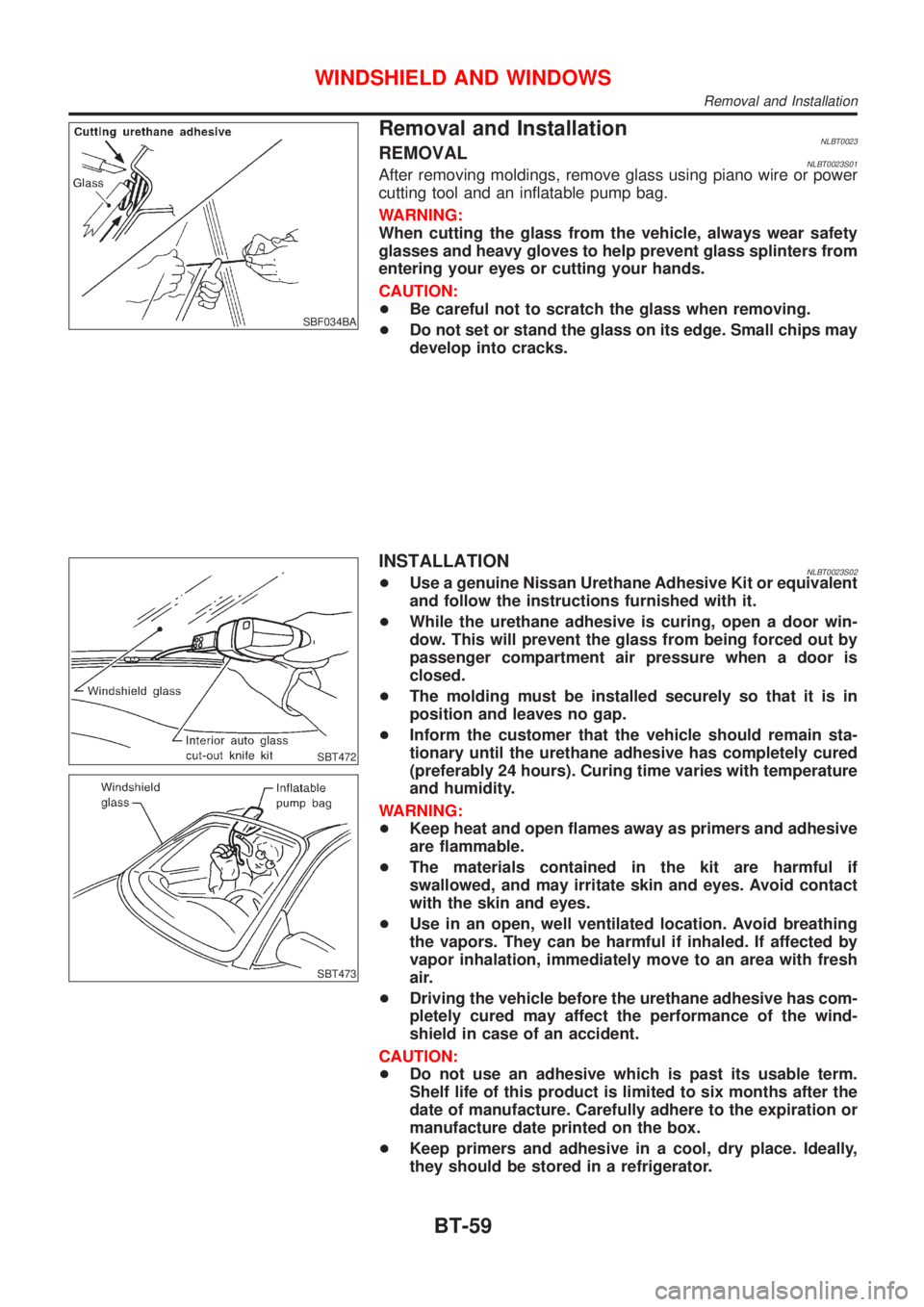
Removal and InstallationNLBT0023REMOVALNLBT0023S01After removing moldings, remove glass using piano wire or power
cutting tool and an inflatable pump bag.
WARNING:
When cutting the glass from the vehicle, always wear safety
glasses and heavy gloves to help prevent glass splinters from
entering your eyes or cutting your hands.
CAUTION:
+Be careful not to scratch the glass when removing.
+Do not set or stand the glass on its edge. Small chips may
develop into cracks.
SBT472
SBT473
INSTALLATIONNLBT0023S02+Use a genuine Nissan Urethane Adhesive Kit or equivalent
and follow the instructions furnished with it.
+While the urethane adhesive is curing, open a door win-
dow. This will prevent the glass from being forced out by
passenger compartment air pressure when a door is
closed.
+The molding must be installed securely so that it is in
position and leaves no gap.
+Inform the customer that the vehicle should remain sta-
tionary until the urethane adhesive has completely cured
(preferably 24 hours). Curing time varies with temperature
and humidity.
WARNING:
+Keep heat and open flames away as primers and adhesive
are flammable.
+The materials contained in the kit are harmful if
swallowed, and may irritate skin and eyes. Avoid contact
with the skin and eyes.
+Use in an open, well ventilated location. Avoid breathing
the vapors. They can be harmful if inhaled. If affected by
vapor inhalation, immediately move to an area with fresh
air.
+Driving the vehicle before the urethane adhesive has com-
pletely cured may affect the performance of the wind-
shield in case of an accident.
CAUTION:
+Do not use an adhesive which is past its usable term.
Shelf life of this product is limited to six months after the
date of manufacture. Carefully adhere to the expiration or
manufacture date printed on the box.
+Keep primers and adhesive in a cool, dry place. Ideally,
they should be stored in a refrigerator.
WINDSHIELD AND WINDOWS
Removal and Installation
BT-59
Page 403 of 3051
SBR820BA
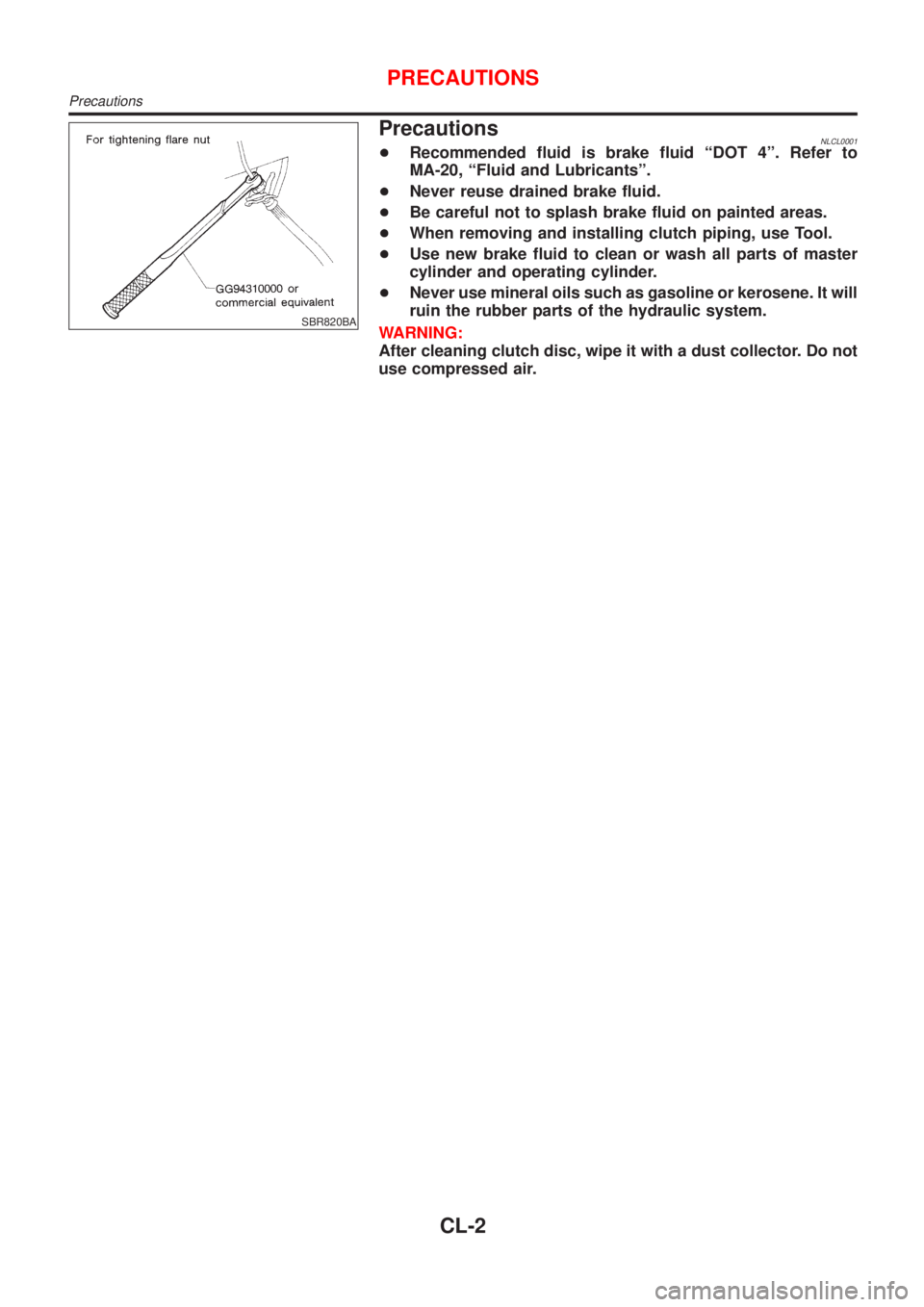
PrecautionsNLCL0001+Recommended fluid is brake fluid ªDOT 4º. Refer to
MA-20, ªFluid and Lubricantsº.
+Never reuse drained brake fluid.
+Be careful not to splash brake fluid on painted areas.
+When removing and installing clutch piping, use Tool.
+Use new brake fluid to clean or wash all parts of master
cylinder and operating cylinder.
+Never use mineral oils such as gasoline or kerosene. It will
ruin the rubber parts of the hydraulic system.
WARNING:
After cleaning clutch disc, wipe it with a dust collector. Do not
use compressed air.
PRECAUTIONS
Precautions
CL-2
Page 446 of 3051
Precautions for Supplemental Restraint System
(SRS) ªAIR BAGº and ªSEAT BELT
PRE-TENSIONERº
NLEC1262The Supplemental Restraint System ªAIR BAGº and ªSEAT BELT PRE-TENSIONERº, used along with a seat
belt, help to reduce the risk or severity of injury to the driver and front passenger in a frontal collision. The
Supplemental Restraint System consists of air bag modules (located in the center of the steering wheel and
on the instrument panel on the passenger side), seat belt pre-tensioners, a diagnosis sensor unit, warning
lamp, wiring harness and spiral cable.
In addition to the supplemental air bag modules for a frontal collision, the supplemental side air bag used along
with the seat belt helps to reduce the risk or severity of injury to the driver and front passenger in a side col-
lision. The supplemental side air bag consists of air bag modules (located in the outer side of front seats),
satellite sensor, diagnosis sensor unit (one of components of supplemental air bags for a frontal collision),
wiring harness, warning lamp (one of components of supplemental air bags for a frontal collision). Information
necessary to service the system safely is included in theRS sectionof this Service Manual.
WARNING:
+To avoid rendering the SRS inoperative, which could increase the risk of personal injury or death
in the event of a collision which would result in air bag inflation, all maintenance must be performed
by an authorized NISSAN dealer.
+Improper maintenance, including incorrect removal and installation of the SRS, can lead to per-
sonal injury caused by unintentional activation of the system.
+Do not use electrical test equipment on any circuit related to the SRS unless instructed to in this
Service Manual. SRS wiring harnesses can be identified with yellow harness connector (and with
yellow harness protector or yellow insulation tape before the harness connectors).
Precautions for On Board Diagnostic (OBD)
System of Engine
NLEC0003The ECM has an on board diagnostic system. It will light up the malfunction indicator (MI) to warn the driver
of a malfunction causing emission deterioration.
CAUTION:
+Be sure to turn the ignition switch ªOFFº and disconnect the negative battery terminal before any
repair or inspection work. The open/short circuit of related switches, sensors, solenoid valves, etc.
will cause the MI to light up.
+Be sure to connect and lock the connectors securely after work. A loose (unlocked) connector will
cause the MI to light up due to the open circuit. (Be sure the connector is free from water, grease,
dirt, bent terminals, etc.)
+Certain systems and components, especially those related to OBD, may use a new style slide-
locking type harness connector.
For description and how to disconnect, refer to EL section, ªDescriptionº, ªHARNESS CONNEC-
TORº.
+Be sure to route and secure the harnesses properly after work. The interference of the harness with
a bracket, etc. may cause the MI to light up due to the short circuit.
+Be sure to connect rubber tubes properly after work. A misconnected or disconnected rubber tube
may cause the MI to light up due to the malfunction of fuel injection system, etc.
+Be sure to erase the unnecessary malfunction information (repairs completed) from the ECM before
returning the vehicle to the customer.
PRECAUTIONSQG18DE
Precautions for Supplemental Restraint System (SRS) ªAIR BAGº and ªSEAT BELT PRE-TENSIONERº
EC-21
Page 499 of 3051
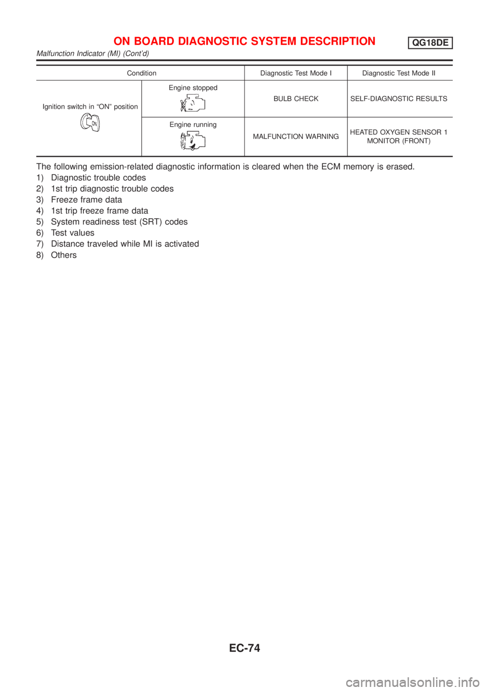
Condition Diagnostic Test Mode I Diagnostic Test Mode II
Ignition switch in ªONº position
Engine stopped
BULB CHECK SELF-DIAGNOSTIC RESULTS
Engine running
MALFUNCTION WARNINGHEATED OXYGEN SENSOR 1
MONITOR (FRONT)
The following emission-related diagnostic information is cleared when the ECM memory is erased.
1) Diagnostic trouble codes
2) 1st trip diagnostic trouble codes
3) Freeze frame data
4) 1st trip freeze frame data
5) System readiness test (SRT) codes
6) Test values
7) Distance traveled while MI is activated
8) Others
ON BOARD DIAGNOSTIC SYSTEM DESCRIPTIONQG18DE
Malfunction Indicator (MI) (Cont'd)
EC-74
Page 800 of 3051
SEF621WA
SEF646X
SEC163BA
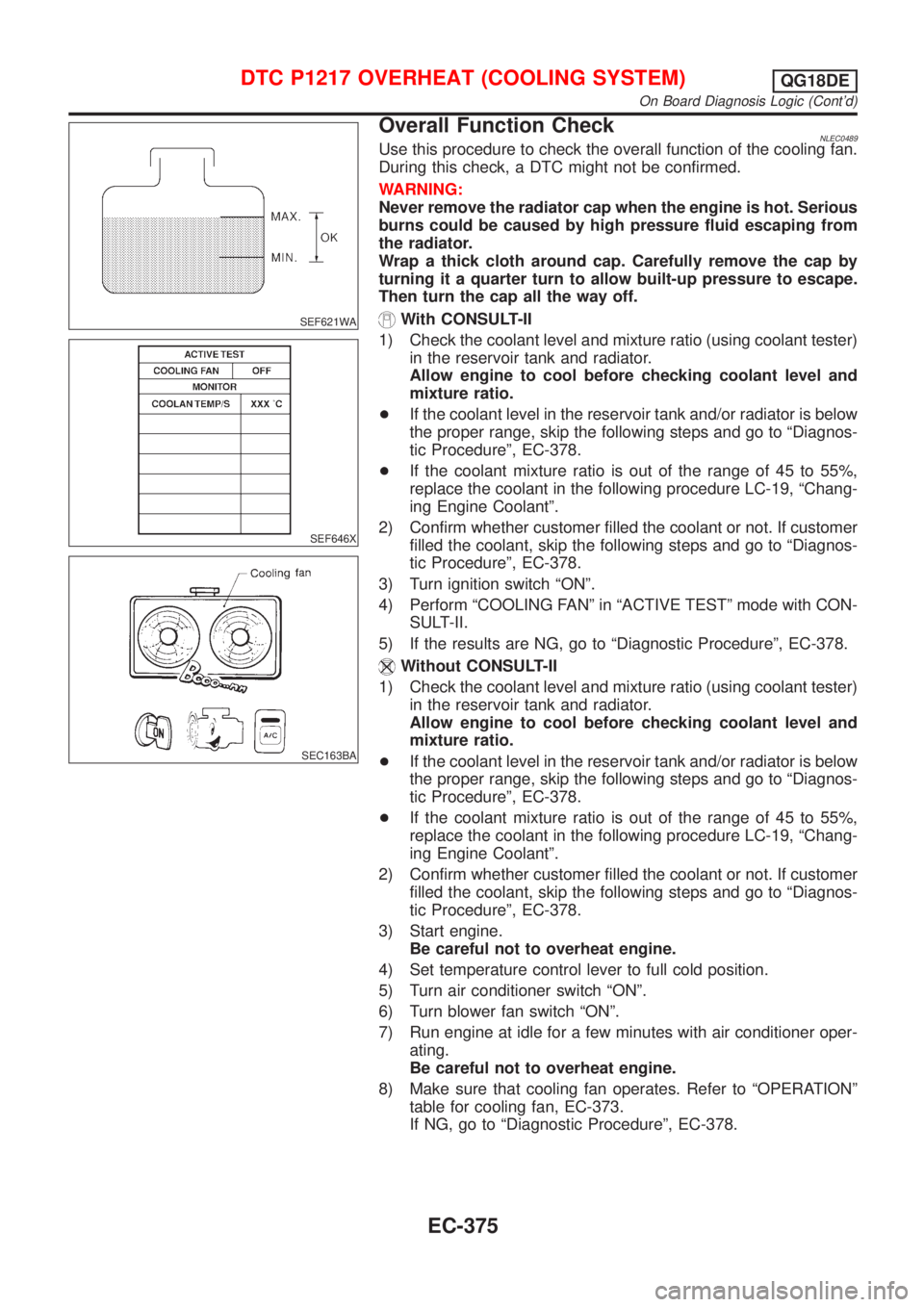
Overall Function CheckNLEC0489Use this procedure to check the overall function of the cooling fan.
During this check, a DTC might not be confirmed.
WARNING:
Never remove the radiator cap when the engine is hot. Serious
burns could be caused by high pressure fluid escaping from
the radiator.
Wrap a thick cloth around cap. Carefully remove the cap by
turning it a quarter turn to allow built-up pressure to escape.
Then turn the cap all the way off.
With CONSULT-II
1) Check the coolant level and mixture ratio (using coolant tester)
in the reservoir tank and radiator.
Allow engine to cool before checking coolant level and
mixture ratio.
+If the coolant level in the reservoir tank and/or radiator is below
the proper range, skip the following steps and go to ªDiagnos-
tic Procedureº, EC-378.
+If the coolant mixture ratio is out of the range of 45 to 55%,
replace the coolant in the following procedure LC-19, ªChang-
ing Engine Coolantº.
2) Confirm whether customer filled the coolant or not. If customer
filled the coolant, skip the following steps and go to ªDiagnos-
tic Procedureº, EC-378.
3) Turn ignition switch ªONº.
4) Perform ªCOOLING FANº in ªACTIVE TESTº mode with CON-
SULT-II.
5) If the results are NG, go to ªDiagnostic Procedureº, EC-378.
Without CONSULT-II
1) Check the coolant level and mixture ratio (using coolant tester)
in the reservoir tank and radiator.
Allow engine to cool before checking coolant level and
mixture ratio.
+If the coolant level in the reservoir tank and/or radiator is below
the proper range, skip the following steps and go to ªDiagnos-
tic Procedureº, EC-378.
+If the coolant mixture ratio is out of the range of 45 to 55%,
replace the coolant in the following procedure LC-19, ªChang-
ing Engine Coolantº.
2) Confirm whether customer filled the coolant or not. If customer
filled the coolant, skip the following steps and go to ªDiagnos-
tic Procedureº, EC-378.
3) Start engine.
Be careful not to overheat engine.
4) Set temperature control lever to full cold position.
5) Turn air conditioner switch ªONº.
6) Turn blower fan switch ªONº.
7) Run engine at idle for a few minutes with air conditioner oper-
ating.
Be careful not to overheat engine.
8) Make sure that cooling fan operates. Refer to ªOPERATIONº
table for cooling fan, EC-373.
If NG, go to ªDiagnostic Procedureº, EC-378.
DTC P1217 OVERHEAT (COOLING SYSTEM)QG18DE
On Board Diagnosis Logic (Cont'd)
EC-375
Page 980 of 3051
Precautions for Supplemental Restraint System
(SRS) ªAIR BAGº and ªSEAT BELT
PRE-TENSIONERº
NLEC1745The Supplemental Restraint System ªAIR BAGº and ªSEAT BELT PRE-TENSIONERº, used along with a seat
belt, help to reduce the risk or severity of injury to the driver and front passenger in a frontal collision. The
Supplemental Restraint System consists of air bag modules (located in the center of the steering wheel and
on the instrument panel on the passenger side), seat belt pre-tensioners, a diagnosis sensor unit, warning
lamp, wiring harness and spiral cable.
In addition to the supplemental air bag modules for a frontal collision, the supplemental side air bag used along
with the seat belt helps to reduce the risk or severity of injury to the driver and front passenger in a side col-
lision. The supplemental side air bag consists of air bag modules (located in the outer side of front seats),
satellite sensor, diagnosis sensor unit (one of components of supplemental air bags for a frontal collision),
wiring harness, warning lamp (one of components of supplemental air bags for a frontal collision). Information
necessary to service the system safely is included in theRS sectionof this Service Manual.
WARNING:
+To avoid rendering the SRS inoperative, which could increase the risk of personal injury or death
in the event of a collision which would result in air bag inflation, all maintenance must be performed
by an authorized NISSAN dealer.
+Improper maintenance, including incorrect removal and installation of the SRS, can lead to per-
sonal injury caused by unintentional activation of the system.
+Do not use electrical test equipment on any circuit related to the SRS unless instructed to in this
Service Manual. SRS wiring harnesses can be identified with yellow harness connector (and with
yellow harness protector or yellow insulation tape before the harness connectors).
Precautions for On Board Diagnostic (OBD)
System of Engine and CVT
NLEC1332The ECM has an on board diagnostic system. It will light up the malfunction indicator (MI) to warn the driver
of a malfunction causing emission deterioration.
CAUTION:
+Be sure to turn the ignition switch ªOFFº and disconnect the negative battery terminal before any
repair or inspection work. The open/short circuit of related switches, sensors, solenoid valves, etc.
will cause the MI to light up.
+Be sure to connect and lock the connectors securely after work. A loose (unlocked) connector will
cause the MI to light up due to the open circuit. (Be sure the connector is free from water, grease,
dirt, bent terminals, etc.)
+Certain systems and components, especially those related to OBD, may use a new style slide-
locking type harness connector.
For description and how to disconnect, refer to EL section, ªDescriptionº, ªHARNESS CONNEC-
TORº.
+Be sure to route and secure the harnesses properly after work. The interference of the harness with
a bracket, etc. may cause the MI to light up due to the short circuit.
+Be sure to connect rubber tubes properly after work. A misconnected or disconnected rubber tube
may cause the MI to light up due to the malfunction of fuel injection system, etc.
+Be sure to erase the unnecessary malfunction information (repairs completed) from the ECM and
TCM (Transmission Control Module) before returning the vehicle to the customer.
PRECAUTIONSSR20DE
Precautions for Supplemental Restraint System (SRS) ªAIR BAGº and ªSEAT BELT PRE-TENSIONERº
EC-555