2001 NISSAN ALMERA TINO warning
[x] Cancel search: warningPage 2985 of 3051

System DescriptionNLSC0009The alternator provides DC voltage to operate the vehicle’s electrical system and to keep the battery charged.
The voltage output is controlled by the IC regulator.
Power is supplied at all times to alternator terminal 4 (S) through:
+10A fuse (No. 33, located in the fuse and fusible link box).
Terminal B supplies power to charge the battery and operate the vehicle’s electrical system. Output voltage
is controlled by the IC regulator at terminal 4 (S) detecting the input voltage. The charging circuit is protected
by the 80A (QG engine models except for Northen Europe and cold spec.) or 100A (SR, YD engine models
and QG engine models for Northen Europe and cold spec.) fusible link.
The alternator is grounded to the engine block.
With the ignition switch in the ON or START position, power is supplied
+through 10A fuse [No. 30, located in the fuse block (J/B)]
+to combination meter terminal 9
Ground is supplied to terminal 22 of the combination meter through terminal 3 (L) of the alternator. With power
and ground supplied, the charge warning lamp will illuminate. When the alternator is providing sufficient volt-
age with the engine running, the ground is opened and the charge warning lamp will go off.
If the charge warning lamp illuminates with the engine running, a fault is indicated.
CHARGING SYSTEM
System Description
SC-24
Page 2988 of 3051

Trouble DiagnosesNLSC0011Before conducting an alternator test, make sure that the battery is fully charged. A 30-volt voltmeter and suit-
able test probes are necessary for the test. The alternator can be checked easily by referring to the Inspec-
tion Table.
+Before starting, inspect the fusible link.
+Use fully charged battery.
WITH IC REGULATORNLSC0011S01
SEL338V
NOTE:
+If the inspection result is OK even though the charging system is malfunctioning, check the B terminal
connection. (Check the tightening torque.)
+When field circuit is open, check condition of rotor coil, rotor slip ring and brush. If necessary, replace faulty
parts with new ones.
MALFUNCTION INDICATORNLSC0011S02The IC regulator warning function activates to illuminate“CHARGE”warning lamp, if any of the following
symptoms occur while alternator is operating:
+Excessive voltage is produced.
+No voltage is produced.
CHARGING SYSTEM
Trouble Diagnoses
SC-27
Page 2997 of 3051
Supplemental Restraint System (SRS) “AIR
BAG” and “SEAT BELT PRE-TENSIONER”
NLST0001The Supplemental Restraint System such as “AIR BAG” and “SEAT BELT PRE-TENSIONER” used along with
a seat belt, helps to reduce the risk or severity of injury to the driver and front passenger for certain types of
collision. The SRS system composition which is available to NISSAN MODEL V10 is as follows (The compo-
sition varies according to the destination and optional equipment.):
+For a frontal collision
The Supplemental Restraint System consists of driver air bag module (located in the center of the steer-
ing wheel), front passenger air bag module (located on the instrument panel on passenger side), front seat
belt pre-tensioners, a diagnosis sensor unit, warning lamp, wiring harness and spiral cable.
+For a side collision
The Supplemental Restraint System consists of front side air bag module (located in the outer side of front
seat), side air bag (satellite) sensor, diagnosis sensor unit (one of components of air bags for a frontal
collision), wiring harness, warning lamp (one of components of air bags for a frontal collision).
Information necessary to service the system safely is included in theRS sectionof this Service Manual.
WARNING:
+To avoid rendering the SRS inoperative, which could increase the risk of personal injury or death
in the event of a collision which would result in air bag inflation, all maintenance should be per-
formed by an authorized NISSAN dealer.
+Improper maintenance, including incorrect removal and installation of the SRS, can lead to per-
sonal injury caused by unintentional activation of the system. For removal of Spiral Cable and Air
Bag Module, see the RS section.
+Do not use electrical test equipment on any circuit related to the SRS unless instructed to in this
Service Manual. Spiral cable and wiring harnesses covered with yellow insulation tape either just
before the harness connectors or for the complete harness are related to the SRS.
Precautions for Steering SystemNLST0003+Before disassembly, thoroughly clean the outside of the unit.
+Disassembly should be done in a clean work area. It is important to prevent the internal parts from
becoming contaminated by dirt or other foreign matter.
+Place disassembled parts in order, on a parts rack, for easier and proper assembly.
+Use nylon cloths or paper towels to clean the parts; common shop rags can leave lint that might
interfere with their operation.
+Before inspection or reassembly, carefully clean all parts with a general purpose, non-flammable
solvent.
+Before assembly, apply a coat of recommended power steering fluid* to hydraulic parts. Vaseline
may be applied to O-rings and seals. Do not use any grease.
+Replace all gaskets, seals and O-rings. Avoid damaging O-rings, seals and gaskets during instal-
lation. Perform functional tests whenever designated.
*: DEXRON
TMIII or equivalent. Refer to MA-20, “Fluids and Lubricants”.
PRECAUTIONS
Supplemental Restraint System (SRS) “AIR BAG” and “SEAT BELT PRE-TENSIONER”
ST-2
Page 3004 of 3051
SST834-I
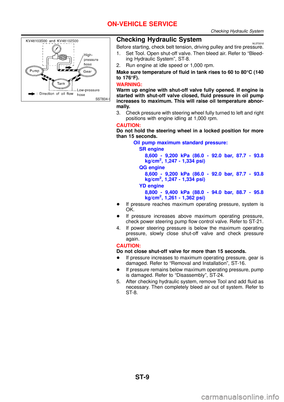
Checking Hydraulic SystemNLST0016Before starting, check belt tension, driving pulley and tire pressure.
1. Set Tool. Open shut-off valve. Then bleed air. Refer to“Bleed-
ing Hydraulic System”, ST-8.
2. Run engine at idle speed or 1,000 rpm.
Make sure temperature of fluid in tank rises to 60 to 80°C (140
to 176°F).
WARNING:
Warm up engine with shut-off valve fully opened. If engine is
started with shut-off valve closed, fluid pressure in oil pump
increases to maximum. This will raise oil temperature abnor-
mally.
3. Check pressure with steering wheel fully turned to left and right
positions with engine idling at 1,000 rpm.
CAUTION:
Do not hold the steering wheel in a locked position for more
than 15 seconds.
Oil pump maximum standard pressure:
SR engine
8,600 - 9,200 kPa (86.0 - 92.0 bar, 87.7 - 93.8
kg/cm
2, 1,247 - 1,334 psi)
QG engine
8,600 - 9,200 kPa (86.0 - 92.0 bar, 87.7 - 93.8
kg/cm
2, 1,247 - 1,334 psi)
YD engine
8,800 - 9,400 kPa (88.0 - 94.0 bar, 88.7 - 95.8
kg/cm
2, 1,261 - 1,362 psi)
+If pressure reaches maximum operating pressure, system is
OK.
+If pressure increases above maximum operating pressure,
check power steering pump flow control valve. Refer to ST-21.
4. If power steering pressure is below the maximum operating
pressure, slowly close shut-off valve and check pressure
again.
CAUTION:
Do not close shut-off valve for more than 15 seconds.
+If pressure increases to maximum operating pressure, gear is
damaged. Refer to“Removal and Installation”, ST-16.
+If pressure remains below maximum operating pressure, pump
is damaged. Refer to“Disassembly”, ST-24.
5. After checking hydraulic system, remove Tool and add fluid as
necessary. Then completely bleed air out of system. Refer to
ST-8.
ON-VEHICLE SERVICE
Checking Hydraulic System
ST-9
Page 3031 of 3051
SMA829C
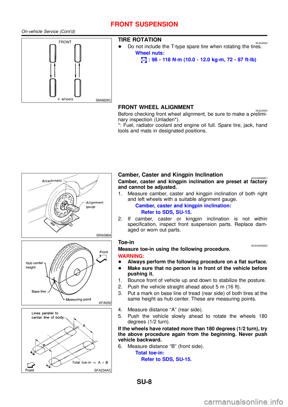
TIRE ROTATIONNLSU0043+Do not include the T-type spare tire when rotating the tires.
Wheel nuts:
:98-118N·m (10.0 - 12.0 kg-m, 72 - 87 ft-lb)
FRONT WHEEL ALIGNMENTNLSU0045Before checking front wheel alignment, be sure to make a prelimi-
nary inspection (Unladen*).
*: Fuel, radiator coolant and engine oil full. Spare tire, jack, hand
tools and mats in designated positions.
SRA096A
Camber, Caster and Kingpin InclinationNLSU0045S01Camber, caster and kingpin inclination are preset at factory
and cannot be adjusted.
1. Measure camber, caster and kingpin inclination of both right
and left wheels with a suitable alignment gauge.
Camber, caster and kingpin inclination:
Refer to SDS, SU-15.
2. If camber, caster or kingpin inclination is not within
specification, inspect front suspension parts. Replace dam-
aged or worn out parts.
AFA050
Toe-inNLSU0045S02Measure toe-in using the following procedure.
WARNING:
+Always perform the following procedure on a flat surface.
+Make sure that no person is in front of the vehicle before
pushing it.
1. Bounce front of vehicle up and down to stabilize the posture.
2. Push the vehicle straight ahead about 5 m (16 ft).
3. Put a mark on base line of tread (rear side) of both tires at the
same height as hub center. These are measuring points.
SFA234AC
4. Measure distance“A”(rear side).
5. Push the vehicle slowly ahead to rotate the wheels 180
degrees (1/2 turn).
If the wheels have rotated more than 180 degrees (1/2 turn), try
the above procedure again from the beginning. Never push
vehicle backward.
6. Measure distance“B”(front side).
Total toe-in:
Refer to SDS, SU-15.
FRONT SUSPENSION
On-vehicle Service (Cont’d)
SU-8
Page 3034 of 3051

SFA956A
REMOVAL AND INSTALLATION=NLSU0009+Remove shock absorber fixing bolt and nut (to hoodledge).
+Do not remove piston rod lock nut on vehicle.
SSU002
DISASSEMBLYNLSU00101. Set shock absorber on vise, thenloosenpiston rod lock nut.
+Do not remove piston rod lock nut at this time.
2. Compress spring with Tool so that shock absorber mounting
insulator can be turned by hand.
WARNING:
Make sure that the pawls of the two spring compressors are
firmly hooked on the spring. The spring compressors must be
tightened alternately so as not to tilt the spring.
SSU003
3. Remove piston rod lock nut.
INSPECTIONNLSU0011Shock Absorber AssemblyNLSU0011S01+Check for smooth operation through a full stroke, both com-
pression and extension.
+Check for oil leakage on welded or gland packing portions.
+Check piston rod for cracks, deformation or other damage.
Replace if necessary.
Mounting Insulator and Rubber PartsNLSU0011S02+Check cemented rubber-to-metal portion for separation or
cracks. Check rubber parts for deterioration.
Replace if necessary.
Thrust BearingNLSU0011S06+Check thrust bearing parts for abnormal noise or excessive
rattle in axial direction.
+Replace if necessary.
Coil SpringNLSU0011S03+Check for cracks, deformation or other damage. Replace if
necessary.
FRONT SUSPENSION
Coil Spring and Shock Absorber (Cont’d)
SU-11
Page 3044 of 3051
SFA614B
SFA234AC
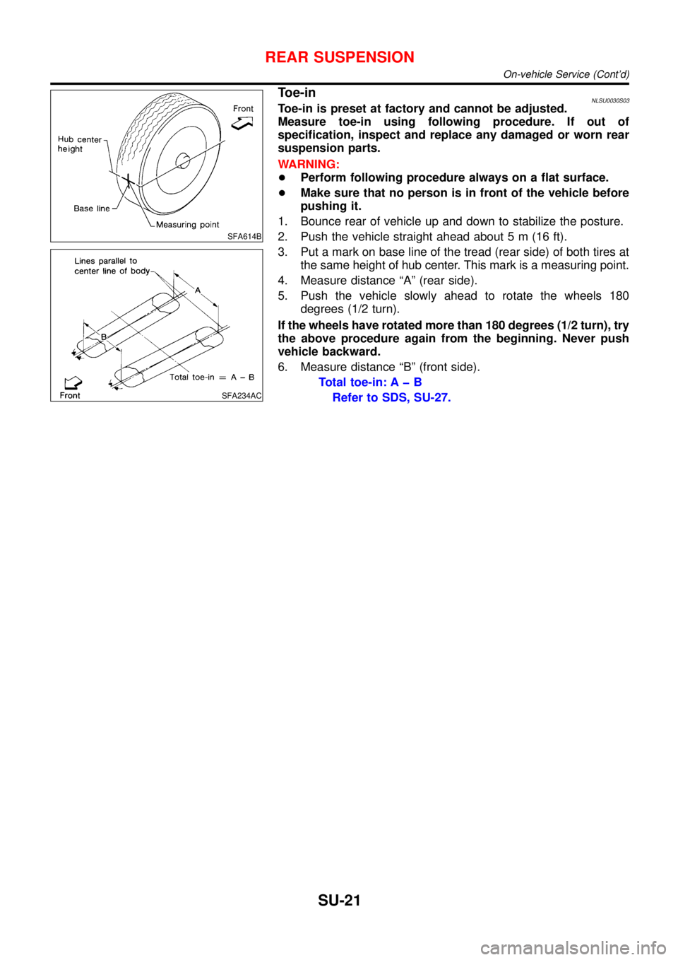
Toe-inNLSU0030S03Toe-in is preset at factory and cannot be adjusted.
Measure toe-in using following procedure. If out of
specification, inspect and replace any damaged or worn rear
suspension parts.
WARNING:
+Perform following procedure always on a flat surface.
+Make sure that no person is in front of the vehicle before
pushing it.
1. Bounce rear of vehicle up and down to stabilize the posture.
2. Push the vehicle straight ahead about 5 m (16 ft).
3. Put a mark on base line of the tread (rear side) of both tires at
the same height of hub center. This mark is a measuring point.
4. Measure distance“A”(rear side).
5. Push the vehicle slowly ahead to rotate the wheels 180
degrees (1/2 turn).
If the wheels have rotated more than 180 degrees (1/2 turn), try
the above procedure again from the beginning. Never push
vehicle backward.
6. Measure distance“B”(front side).
Total toe-in: A � B
Refer to SDS, SU-27.
REAR SUSPENSION
On-vehicle Service (Cont’d)
SU-21
Page 3047 of 3051
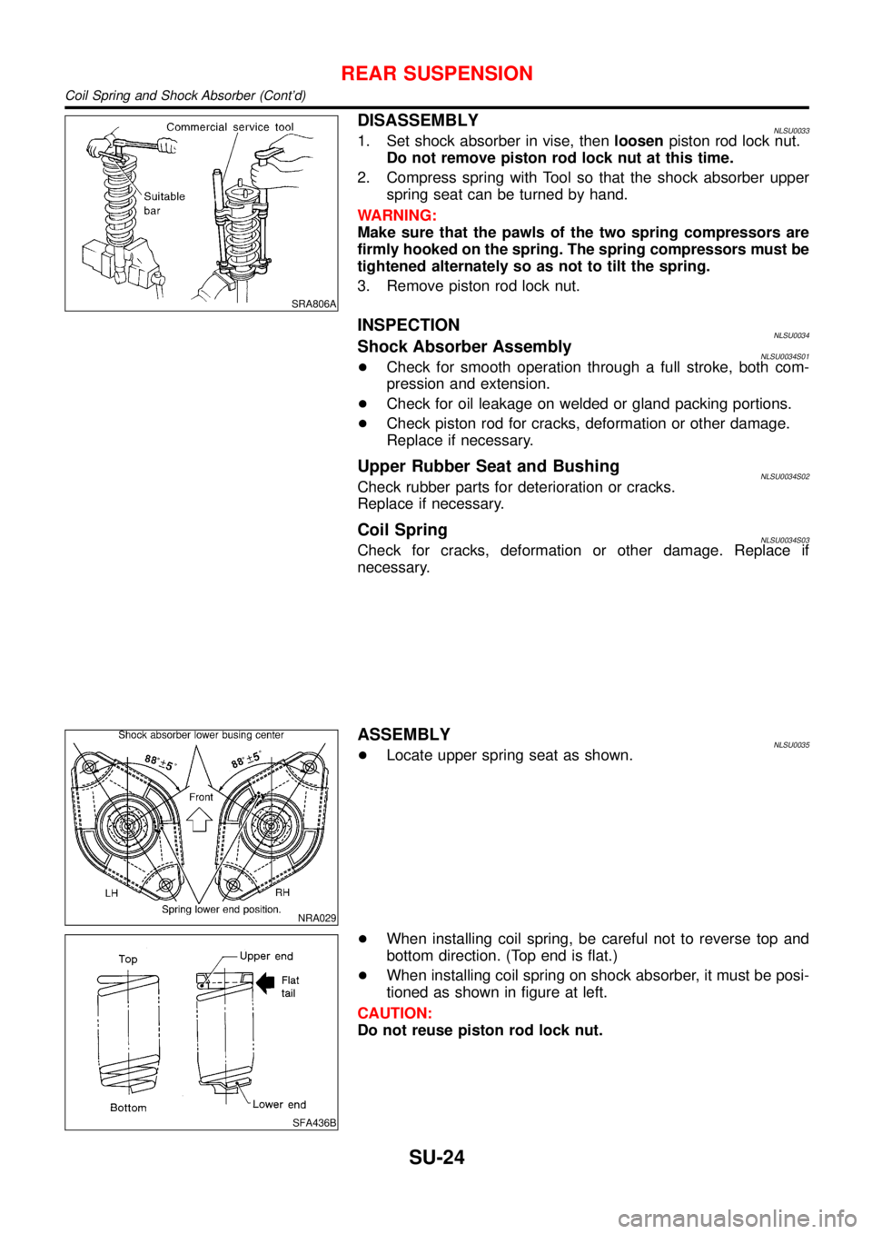
SRA806A
DISASSEMBLYNLSU00331. Set shock absorber in vise, thenloosenpiston rod lock nut.
Do not remove piston rod lock nut at this time.
2. Compress spring with Tool so that the shock absorber upper
spring seat can be turned by hand.
WARNING:
Make sure that the pawls of the two spring compressors are
firmly hooked on the spring. The spring compressors must be
tightened alternately so as not to tilt the spring.
3. Remove piston rod lock nut.
INSPECTIONNLSU0034Shock Absorber AssemblyNLSU0034S01+Check for smooth operation through a full stroke, both com-
pression and extension.
+Check for oil leakage on welded or gland packing portions.
+Check piston rod for cracks, deformation or other damage.
Replace if necessary.
Upper Rubber Seat and BushingNLSU0034S02Check rubber parts for deterioration or cracks.
Replace if necessary.
Coil SpringNLSU0034S03Check for cracks, deformation or other damage. Replace if
necessary.
NRA029
ASSEMBLYNLSU0035+Locate upper spring seat as shown.
SFA436B
+When installing coil spring, be careful not to reverse top and
bottom direction. (Top end is flat.)
+When installing coil spring on shock absorber, it must be posi-
tioned as shown in figure at left.
CAUTION:
Do not reuse piston rod lock nut.
REAR SUSPENSION
Coil Spring and Shock Absorber (Cont’d)
SU-24