Page 262 of 3051

SBR976B
SBR932C
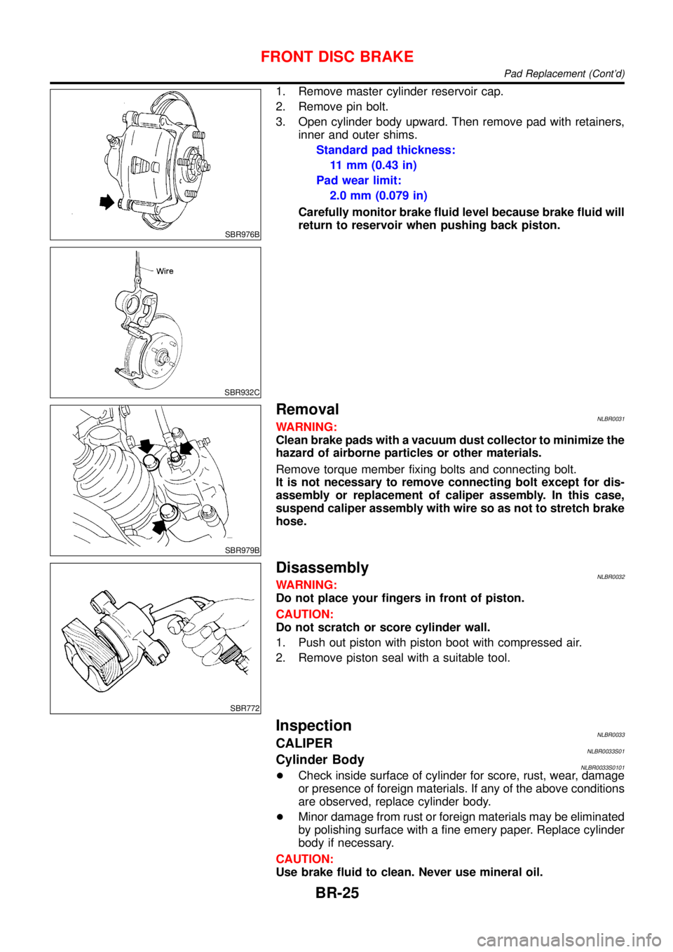
1. Remove master cylinder reservoir cap.
2. Remove pin bolt.
3. Open cylinder body upward. Then remove pad with retainers,
inner and outer shims.
Standard pad thickness:
11 mm (0.43 in)
Pad wear limit:
2.0 mm (0.079 in)
Carefully monitor brake fluid level because brake fluid will
return to reservoir when pushing back piston.
SBR979B
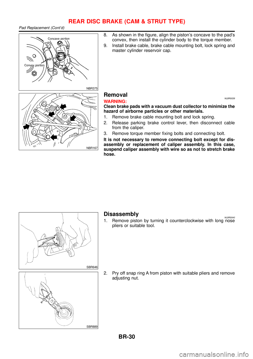
RemovalNLBR0031WARNING:
Clean brake pads with a vacuum dust collector to minimize the
hazard of airborne particles or other materials.
Remove torque member fixing bolts and connecting bolt.
It is not necessary to remove connecting bolt except for dis-
assembly or replacement of caliper assembly. In this case,
suspend caliper assembly with wire so as not to stretch brake
hose.
SBR772
DisassemblyNLBR0032WARNING:
Do not place your fingers in front of piston.
CAUTION:
Do not scratch or score cylinder wall.
1. Push out piston with piston boot with compressed air.
2. Remove piston seal with a suitable tool.
InspectionNLBR0033CALIPERNLBR0033S01Cylinder BodyNLBR0033S0101+Check inside surface of cylinder for score, rust, wear, damage
or presence of foreign materials. If any of the above conditions
are observed, replace cylinder body.
+Minor damage from rust or foreign materials may be eliminated
by polishing surface with a fine emery paper. Replace cylinder
body if necessary.
CAUTION:
Use brake fluid to clean. Never use mineral oil.
FRONT DISC BRAKE
Pad Replacement (Cont’d)
BR-25
Page 265 of 3051
ComponentNLBR0038
NBR366
1. Cable guide
2. Cylinder
3. Toggle lever
4. Pin
5. Pin boot
6. Torque member
7. Inner shim
8. Inner pad
9. Outer pad
10. Outer shim11. Strut
12. O-ring
13. Push rod
14. Key plate
15. Retaining washer
16. Spring
17. Spring cover
18. Snap ring B
19. Piston seal
20. Snap ring A21. Washer
22. Wave washer
23. Washer
24. Bearing
25. Adjuster
26. Cup
27. Piston
28. Piston boot
29. Sleeve
Pad ReplacementNLBR0037WARNING:
Clean brake pads with a vacuum dust collector to minimize the
hazard of airborne particles or other materials.
CAUTION:
+When cylinder body is open, do not depress brake pedal
because piston will pop out.
+Be careful not to damage piston boot or get oil on rotor.
Always replace shims in replacing pads.
+If shims are rusted or show peeling of rubber coat, replace
them with new shims.
REAR DISC BRAKE (CAM & STRUT TYPE)
Component
BR-28
Page 267 of 3051

NBR375
8. As shown in the figure, align the piston’s concave to the pad’s
convex, then install the cylinder body to the torque member.
9. Install brake cable, brake cable mounting bolt, lock spring and
master cylinder reservoir cap.
NBR167
RemovalNLBR0039WARNING:
Clean brake pads with a vacuum dust collector to minimize the
hazard of airborne particles or other materials.
1. Remove brake cable mounting bolt and lock spring.
2. Release parking brake control lever, then disconnect cable
from the caliper.
3. Remove torque member fixing bolts and connecting bolt.
It is not necessary to remove connecting bolt except for dis-
assembly or replacement of caliper assembly. In this case,
suspend caliper assembly with wire so as not to stretch brake
hose.
SBR646
DisassemblyNLBR00401. Remove piston by turning it counterclockwise with long nose
pliers or suitable tool.
SBR889
2. Pry off snap ring A from piston with suitable pliers and remove
adjusting nut.
REAR DISC BRAKE (CAM & STRUT TYPE)
Pad Replacement (Cont’d)
BR-30
Page 273 of 3051

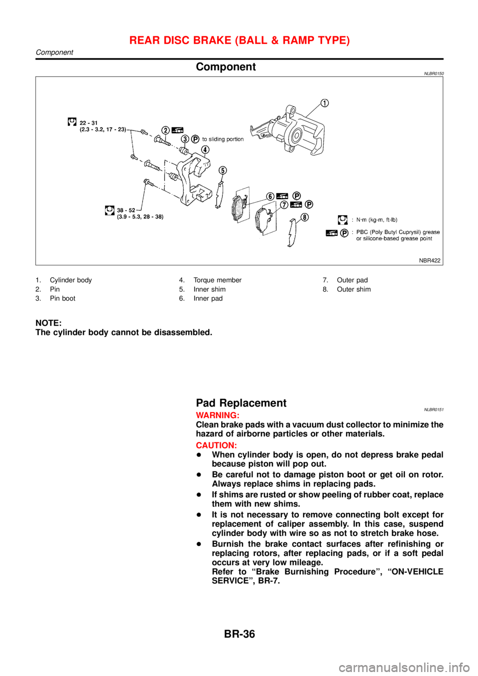
ComponentNLBR0150
NBR422
1. Cylinder body
2. Pin
3. Pin boot4. Torque member
5. Inner shim
6. Inner pad7. Outer pad
8. Outer shim
NOTE:
The cylinder body cannot be disassembled.
Pad ReplacementNLBR0151WARNING:
Clean brake pads with a vacuum dust collector to minimize the
hazard of airborne particles or other materials.
CAUTION:
+When cylinder body is open, do not depress brake pedal
because piston will pop out.
+Be careful not to damage piston boot or get oil on rotor.
Always replace shims in replacing pads.
+If shims are rusted or show peeling of rubber coat, replace
them with new shims.
+It is not necessary to remove connecting bolt except for
replacement of caliper assembly. In this case, suspend
cylinder body with wire so as not to stretch brake hose.
+Burnish the brake contact surfaces after refinishing or
replacing rotors, after replacing pads, or if a soft pedal
occurs at very low mileage.
Refer to“Brake Burnishing Procedure”,“ON-VEHICLE
SERVICE”, BR-7.
REAR DISC BRAKE (BALL & RAMP TYPE)
Component
BR-36
Page 275 of 3051

NBR427
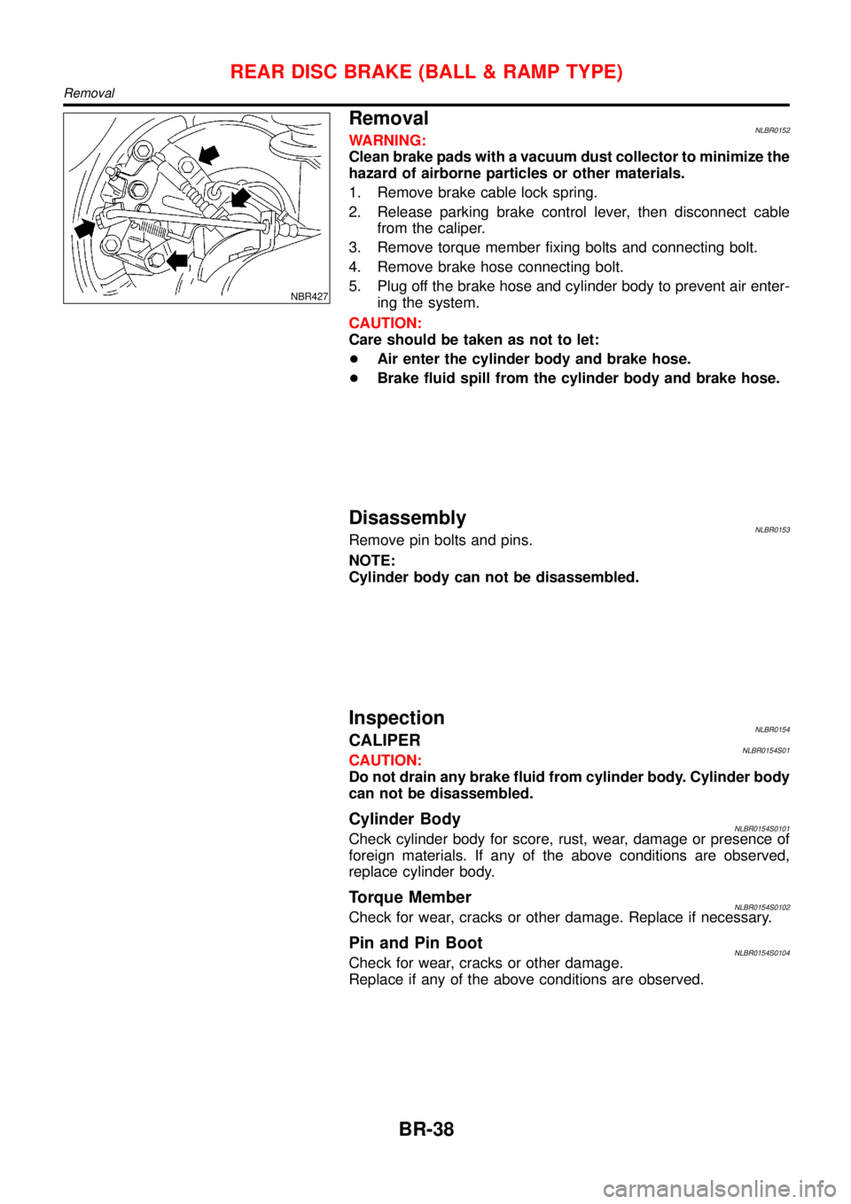
RemovalNLBR0152WARNING:
Clean brake pads with a vacuum dust collector to minimize the
hazard of airborne particles or other materials.
1. Remove brake cable lock spring.
2. Release parking brake control lever, then disconnect cable
from the caliper.
3. Remove torque member fixing bolts and connecting bolt.
4. Remove brake hose connecting bolt.
5. Plug off the brake hose and cylinder body to prevent air enter-
ing the system.
CAUTION:
Care should be taken as not to let:
+Air enter the cylinder body and brake hose.
+Brake fluid spill from the cylinder body and brake hose.
DisassemblyNLBR0153Remove pin bolts and pins.
NOTE:
Cylinder body can not be disassembled.
InspectionNLBR0154CALIPERNLBR0154S01CAUTION:
Do not drain any brake fluid from cylinder body. Cylinder body
can not be disassembled.
Cylinder BodyNLBR0154S0101Check cylinder body for score, rust, wear, damage or presence of
foreign materials. If any of the above conditions are observed,
replace cylinder body.
Torque MemberNLBR0154S0102Check for wear, cracks or other damage. Replace if necessary.
Pin and Pin BootNLBR0154S0104Check for wear, cracks or other damage.
Replace if any of the above conditions are observed.
REAR DISC BRAKE (BALL & RAMP TYPE)
Removal
BR-38
Page 277 of 3051
ComponentsNLBR0044
NBR368
SBR897D
Removal and InstallationNLBR00451. To remove parking brake cable, first remove center console.
2. Disconnect warning lamp switch connector.
3. Remove adjusting nut.
4. Remove bolts and nuts securing parking brake cable.
5. Remove parking brake device.
SBR025D
6. Remove lock plate and disconnect cable.
InspectionNLBR00461. Check control lever for wear or other damage. Replace if nec-
essary.
2. Check wires for discontinuity or deterioration. Replace if nec-
essary.
3. Check warning lamp and switch. Replace if necessary.
4. Check parts at each connecting portion and, if found deformed
or damaged, replace.
PARKING BRAKE CONTROL
Components
BR-40
Page 278 of 3051
SBR768E
AdjustmentNLBR0047Before or after adjustment, pay attention to the following points.
+For rear disc brake be sure that toggle lever returns to stop-
per when parking brake lever is released.
+There is no drag when parking brake lever is released.
+Vehicle is unladen.
1. Adjust clearance between pad and rotor as follows:
a. Release parking brake lever and loosen adjusting nut.
b. Depress brake pedal fully at least 10 times with engine run-
ning.
SBR756E
2. Pull control lever 10 times or more to make a lever stroke of
195 mm (7.68 in). At5-6notches, adjust the parking brake
cable by turning the adjusting nut.
SBR033A
3. Pull control lever with specified amount of force. Check lever
stroke and ensure smooth operation.
Number of notches
5-6
4. Bend warning lamp switch plate to ensure:
+Warning lamp comes on when lever is lifted“A”notches.
+Warning lamp goes out when lever is fully released.
Number of“A”notches: 1
PARKING BRAKE CONTROL
Adjustment
BR-41
Page 279 of 3051

PurposeNLBR0082The ABS consists of electronic and hydraulic components. It allows to control the braking force so that lock-
ing of the wheels can be avoided.
The ABS:
1) Ensures proper tracking performance through steering wheel operation.
2) Enables obstacles to be avoided through steering wheel operation.
3) Ensures vehicle stability by preventing flat spins.
ABS (Anti-Lock Brake System) OperationNLBR0083+When the vehicle speed is less than 10 km/h (6 MPH) this system does not work.
+The Anti-Lock Brake System (ABS) has self-test capabilities. The system turns on the ABS warning lamp
for 1 second after turning the ignition switch ON. The system performs another test the first time the vehicle
reaches 6 km/h (4 MPH). A mechanical noise may be heard as the ABS performs a self-test. This is a
normal part of the self-test feature. If a malfunction is found during this check, the ABS warning lamp will
come on.
+During ABS operation, a mechanical noise may be heard. This is a normal condition.
ABS Hydraulic CircuitNLBR0084
SBR757E
1. Inlet solenoid valve
2. Outlet solenoid valve
3. Reservoir4. Pump
5. Motor6. Bypass check valve
7. Damper
DESCRIPTIONABS
Purpose
BR-42