Page 1900 of 3051
YEL426C
WARNING CHIME
Wiring Diagram Ð CHIME Ð (Cont'd)
EL-169
Page 1901 of 3051
Trouble DiagnosesNLEL0455SYMPTOM CHARTNLEL0455S01
REFERENCE PAGE (EL- ) 170 171 172 173 174
SYMPTOM
POWER SUPPLY AND
GROUND CIRCUIT CHECK
DIAGNOSTIC PROCEDURE 1
(LIGHTING SWITCH INPUT
SIGNAL CHECK)
DIAGNOSTIC PROCEDURE 2
(KEY SWITCH INSERT
SIGNAL CHECK)
DIAGNOSTIC PROCEDURE 3
(DOOR UNLOCK SENSOR CHECK)
DIAGNOSTIC PROCEDURE 4
Light warning chime does not acti-
vate.XX X
Ignition key warning chime does not
activate.XXXX
All warning chimes do not activate. XX
POWER SUPPLY AND GROUND CIRCUIT CHECKNLEL0455S02Power Supply Circuit CheckNLEL0455S0201
NEL665
Ground Circuit CheckNLEL0455S0202
NEL666
WARNING CHIME
Trouble Diagnoses
EL-170
Page 1902 of 3051
DIAGNOSTIC PROCEDURE 1 (LIGHTING SWITCH
INPUT SIGNAL CHECK)
=NLEL0455S03
1 CHECK LIGHTING SWITCH INPUT SIGNAL
Check voltage between time control unit terminal 10 and ground.
NEL667
OK or NG
OK©Lighting switch is OK.
NG©Check the following.
+10A fuse (No. 38, located in the fuse and fusible link box)
+Harness for open or short between time control unit and lighting switch/daytime light
control unit
+Lighting switch
WARNING CHIME
Trouble Diagnoses (Cont'd)
EL-171
Page 1903 of 3051
DIAGNOSTIC PROCEDURE 2 (KEY SWITCH INSERT
SIGNAL CHECK)
=NLEL0455S04
1 CHECK KEY SWITCH INPUT SIGNAL
Check voltage between time control unit terminal 22 and ground.
NEL653
OK or NG
OK©Key switch is OK.
NG©GO TO 2.
2 CHECK KEY SWITCH (INSERT)
Check continuity between terminals 1 and 2.
NEL787
OK or NG
OK©Check the following.
+10A fuse [No. 12, located in fuse block (J/B)]
+Harness for open or short between key switch and fuse
+Harness for open or short between time control unit and key switch
NG©Replace key switch.
WARNING CHIME
Trouble Diagnoses (Cont'd)
EL-172
Page 1904 of 3051
DIAGNOSTIC PROCEDURE 3 (DOOR UNLOCK SENSOR
CHECK)
NLEL0455S05
1 CHECK DOOR UNLOCK SENSOR INPUT SIGNAL
Check voltage between time control unit terminal 35 and ground.
NEL649
OK or NG
OK©Door unlock sensor is OK.
NG©GO TO 2.
2 CHECK DOOR UNLOCK SENSOR
1. Disconnect door unlock sensor connector.
2. Check continuity between door unlock sensor terminals.
NEL650
OK or NG
OK©Check the following.
+Door unlock sensor ground circuit
+Harness for open or short between time control unit and door unlock sensor
NG©Replace door unlock sensor.
WARNING CHIME
Trouble Diagnoses (Cont'd)
EL-173
Page 1905 of 3051
DIAGNOSTIC PROCEDURE 4NLEL0455S06
1 CHECK IGNITION ON SIGNAL
Check voltage between time control unit terminal 1 or 9 and ground.
NEL665
OK or NG
OK©GO TO 2.
NG©Check the following.
+10A fuse [No. 10, located in fuse block (J/B)]
+15A fuse [No. 5, located in the fuse block (J/B)]
+Harness for open or short between time control unit and fuse
2 CHECK DOOR SWITCH INPUT SIGNAL
Check voltage between time control unit terminal 6 and ground.
NEL647
OK or NG
OK©System is OK.
NG©Check voltage between time control unit terminal 6 and body ground with disconnecting
front door switch (driver side).
If approx. 5V is supplied, GO TO 3.
If approx. 5V is not supplied, replace time control unit.
WARNING CHIME
Trouble Diagnoses (Cont'd)
EL-174
Page 1906 of 3051
3 CHECK DRIVER SIDE DOOR SWITCH
Check continuity between terminals 2 and 3.
NEL648
OK or NG
OK©Check the following.
+Driver side door switch ground circuit and condition
+Harness for open or short between time control unit and driver side door switch
NG©Replace driver side door switch.
WARNING CHIME
Trouble Diagnoses (Cont'd)
EL-175
Page 2053 of 3051

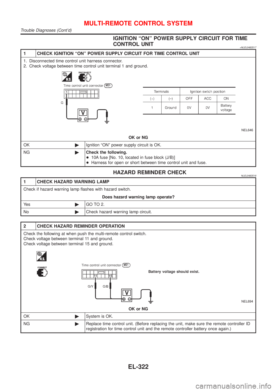
IGNITION ªONº POWER SUPPLY CIRCUIT FOR TIME
CONTROL UNIT
=NLEL0482S17
1 CHECK IGNITION ªONº POWER SUPPLY CIRCUIT FOR TIME CONTROL UNIT
1. Disconnected time control unit harness connector.
2. Check voltage between time control unit terminal 1 and ground.
NEL646
OK or NG
OK©Ignition ªONº power supply circuit is OK.
NG©Check the following.
+10A fuse [No. 10, located in fuse block (J/B)]
+Harness for open or short between time control unit and fuse.
HAZARD REMINDER CHECKNLEL0482S18
1 CHECK HAZARD WARNING LAMP
Check if hazard warning lamp flashes with hazard switch.
Does hazard warning lamp operate?
Ye s©GO TO 2.
No©Check hazard warning lamp circuit.
2 CHECK HAZARD REMINDER OPERATION
Check the following at when push the multi-remote control switch.
Check voltage between terminal 11 and ground.
Check voltage between terminal 15 and ground.
NEL694
OK or NG
OK©System is OK.
NG©Replace time control unit. (Before replacing the unit, make sure the remote controller ID
registration for time control unit and the remote controller battery once again.)
MULTI-REMOTE CONTROL SYSTEM
Trouble Diagnoses (Cont'd)
EL-322