2001 NISSAN ALMERA TINO warning
[x] Cancel search: warningPage 2595 of 3051
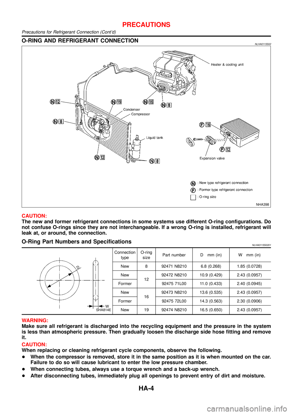
O-RING AND REFRIGERANT CONNECTIONNLHA0115S02
NHA398
CAUTION:
The new and former refrigerant connections in some systems use different O-ring configurations. Do
not confuse O-rings since they are not interchangeable. If a wrong O-ring is installed, refrigerant will
leak at, or around, the connection.
O-Ring Part Numbers and SpecificationsNLHA0115S0201
SHA814E
Connection
typeO-ring
sizePart number D mm (in) W mm (in)
New 8 92471 N8210 6.8 (0.268) 1.85 (0.0728)
New
1292472 N8210 10.9 (0.429) 2.43 (0.0957)
Former 92475 71L00 11.0 (0.433) 2.40 (0.0945)
New
1692473 N8210 13.6 (0.535) 2.43 (0.0957)
Former 92475 72L00 14.3 (0.563) 2.30 (0.0906)
New 19 92474 N8210 16.5 (0.650) 2.43 (0.0957)
WARNING:
Make sure all refrigerant is discharged into the recycling equipment and the pressure in the system
is less than atmospheric pressure. Then gradually loosen the discharge side hose fitting and remove
it.
CAUTION:
When replacing or cleaning refrigerant cycle components, observe the following.
+When the compressor is removed, store it in the same position as it is when mounted on the car.
Failure to do so will cause lubricant to enter the low pressure chamber.
+When connecting tubes, always use a torque wrench and a back-up wrench.
+After disconnecting tubes, immediately plug all openings to prevent entry of dirt and moisture.
PRECAUTIONS
Precautions for Refrigerant Connection (Cont’d)
HA-4
Page 2676 of 3051
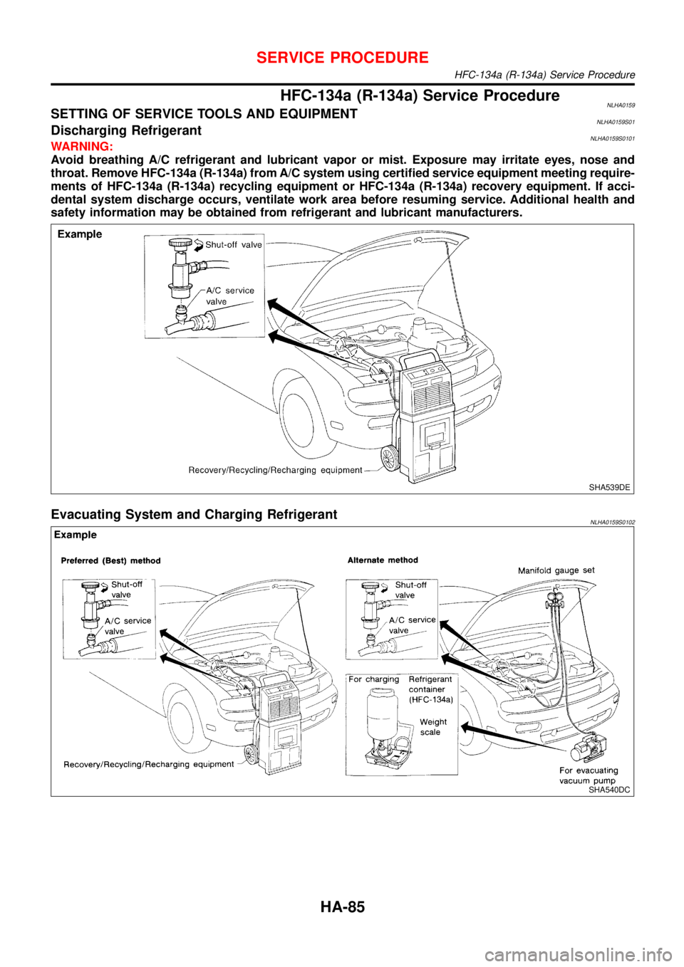
HFC-134a (R-134a) Service ProcedureNLHA0159SETTING OF SERVICE TOOLS AND EQUIPMENTNLHA0159S01Discharging RefrigerantNLHA0159S0101WARNING:
Avoid breathing A/C refrigerant and lubricant vapor or mist. Exposure may irritate eyes, nose and
throat. Remove HFC-134a (R-134a) from A/C system using certified service equipment meeting require-
ments of HFC-134a (R-134a) recycling equipment or HFC-134a (R-134a) recovery equipment. If acci-
dental system discharge occurs, ventilate work area before resuming service. Additional health and
safety information may be obtained from refrigerant and lubricant manufacturers.
SHA539DE
Evacuating System and Charging RefrigerantNLHA0159S0102
SHA540DC
SERVICE PROCEDURE
HFC-134a (R-134a) Service Procedure
HA-85
Page 2699 of 3051
Engine control component parts
location ................................ EC-26, 560, 1071
Engine control module (ECM) ........ EC-358, 880
Engine control system diagram and
chart .................................... EC-32, 566, 1076
Engine coolant temperature sensor
(ECTS) .............................. EC-169, 694, 1150
Engine fail-safe system .................. EC-123, 647
Engine oil precautions .................................. GI-7
Engine outer component parts ........... EM-12, 82
Engine removal ........................ EM-49, 130, 218
Engine room - See Engine
compartment .......................................... BT-66
Engine serial number ................................. GI-39
Evaporative emission (EVAP)
system ........................................... EC-39, 573
Exhaust gas recirculation (EGR)
valve ........... EC-310, 393, 446, 834, 921, 975
Exhaust system ................................... FE-11, 23
Exterior ...................................................... BT-38
F
F/PUMP - Wiring diagram ............. EC-518, 1034
FR02 - Wiring diagram .. EC-187, 207, 216, 415,
712, 732, 741, 945
FR02/H - Wiring diagram ............... EC-223, 422,
748, 952
FUEL - Wiring diagram ... EC-271, 279, 794, 802
Fan switch ................................................. HA-61
Final drive (FF M/T) ...................... MT-47, 63, 77
Finisher, interior - See Trim ....................... BT-28
Finisher, trunk lid ....................................... BT-31
Floor trim ................................................... BT-28
Fluids ........................................................ MA-20
Flywheel (clutch) ....................................... CL-22
Flywheel runout ........................ EM-60, 142, 235
Fog lamp, front, removal and
installation ................................................ BT-7
Fog lamp, front .......................................... EL-95
Fork rod (M/T) ..................................... MT-26, 64
Freeze frame data .............. EC-61, 71, 585, 596
Front axle .................................................... AX-2
Front bumper ............................................... BT-7
Front combination lamp removal and
installation ................................................ BT-7
Front disc brake ........................................ BR-24
Front door .................................................. BT-13
Front fog lamp removal and
installation ................................................ BT-7
Front fog lamp ........................................... EL-95
Front heated oxygen sensor (HO2S)
heater .......................... EC-221, 421, 746, 951
Front heated oxygen sensor (HO2S) ..... EC-184,
192, 198, 204, 214, 414, 709,
717, 723, 729, 739, 944Front seat belt ............................................. RS-5
Front seat .................................................. BT-46
Front suspension ........................................ SU-2
Front washer ............................................ EL-176
Front wiper ............................................... EL-176
Fuel cut control (at no load & high
engine speed) ..................... EC-39, 573, 1081
Fuel gauge ............................................... EL-130
Fuel injection system ............. EC-269, 277, 792,
800, 1079
Fuel injector .................................. EC-494, 1021
Fuel precautions ........................................... GI-8
Fuel pressure check ......................... EC-43, 577
Fuel pressure regulator .................... EC-44, 578
Fuel pressure release ....................... EC-43, 577
Fuel pump relay ............................ EC-516, 1032
Fuel pump ..................................... EC-516, 1032
Fuel system ........................................... FE-5, 15
Fuel tank vacuum relief valve ........... EC-40, 574
Fuse block ............................................... EL-527
Fuse ........................................................... EL-32
Fusible link ................................................. EL-32G
GLOW - Wiring diagram ....................... EC-1267
Garage jack and safety stand .................... GI-43
Gauges .................................................... EL-130
Gear components (M/T) ..................... MT-25, 63
Generator - See Alternator ....................... SC-28
Generic scan tool (GST) ................... EC-93, 617
Glass .......................................................... BT-14
Glow plug .............................................. EC-1267
Glow relay ............................................. EC-1267
Grease ...................................................... MA-20
Ground distribution .............................. EL-33, 48
H
H/LAMP - Wiring diagram .......................... EL-69
HEATER - Wiring diagram ........................ HA-23
HFC134a (R134a) system
precaution ................................................ HA-2
HFC134a (R134a) system service
procedure .............................................. HA-85
HFC134a (R134a) system service
tools ....................................................... HA-10
HFC134a system service equipment
precaution ................................................ HA-6
HORN - Wiring diagram .......................... EL-193
HSEAT - Wiring diagram ......................... EL-234
Harness connector ...................................... EL-5
Harness layout ......................................... EL-452
Hazard warning lamp .............................. EL-101
Headlamp removal and installation ............. BT-7
Headlamp washer .................................... EL-190
ALPHABETICAL INDEX
IDX-4
Page 2703 of 3051
Vehicle speed sensor (VSS) . EC-338, 858, 1172
Viscosity number (SAE) ............................ MA-21
Viscous coupling (FF M/T) ........................ MT-63
W
WARN - Wiring diagram .......................... EL-156
WIP/R - Wiring diagram .......................... EL-184
WIPER - Wiring diagram ......................... EL-178
Warning chime ......................................... EL-165
Warning lamps ......................................... EL-155
Washer, front ........................................... EL-176
Water pump ................................... LC-14, 33, 55
Water temperature gauge ........................ EL-130
Weatherstrip - See Exterior ....................... BT-38
Wheel alignment (rear) ............................. SU-19
Wheel bearing (front) .................................. AX-3Wheel bearing (rear) ................................. AX-22
Wheel hub (front) ........................................ AX-5
Wheel hub (rear) ....................................... AX-23
Wheel sensors (ABS) ............................... BR-90
Wheelarch height ........................................ SU-6
Wheelbase (Dimensions) ........................... GI-41
Wide open & closed throttle position
switch .......................................... EC-175, 700
Width (Dimensions) .................................... GI-41
Window, rear .............................................. BT-59
Windshield ................................................. BT-59
Wiper, front .............................................. EL-176
Wiring diagram (cell code) list ................. EL-525
Wiring diagrams .......................................... GI-11
Withdrawal lever (clutch) ..................... CL-17, 20
Wrist pin - See Piston pin inspection ...... EM-54,
134, 226
ALPHABETICAL INDEX
IDX-8
Page 2708 of 3051
SEM853F
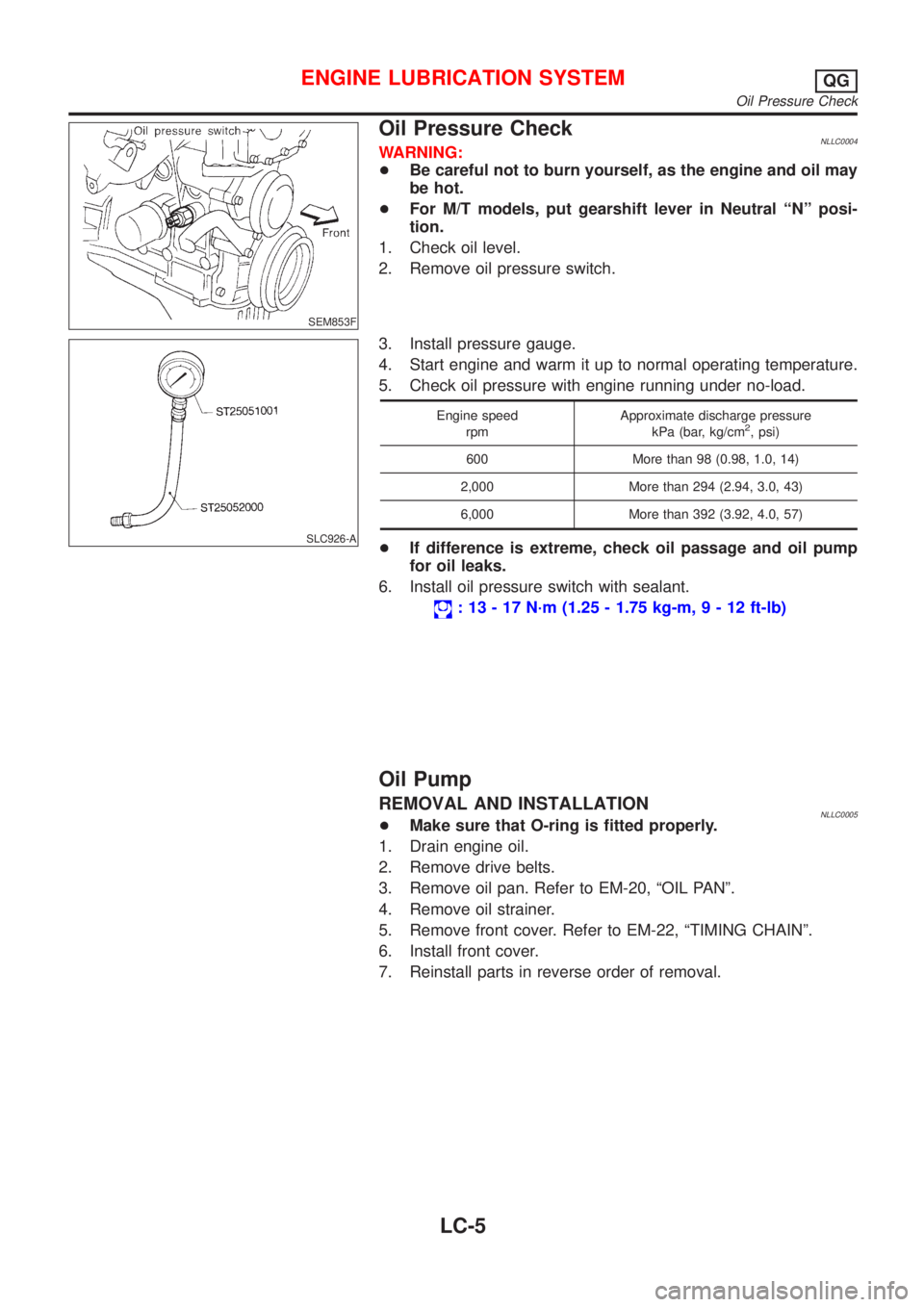
Oil Pressure CheckNLLC0004WARNING:
+Be careful not to burn yourself, as the engine and oil may
be hot.
+For M/T models, put gearshift lever in Neutral ªNº posi-
tion.
1. Check oil level.
2. Remove oil pressure switch.
SLC926-A
3. Install pressure gauge.
4. Start engine and warm it up to normal operating temperature.
5. Check oil pressure with engine running under no-load.
Engine speed
rpmApproximate discharge pressure
kPa (bar, kg/cm2, psi)
600 More than 98 (0.98, 1.0, 14)
2,000 More than 294 (2.94, 3.0, 43)
6,000 More than 392 (3.92, 4.0, 57)
+If difference is extreme, check oil passage and oil pump
for oil leaks.
6. Install oil pressure switch with sealant.
: 13 - 17 N´m (1.25 - 1.75 kg-m,9-12ft-lb)
Oil Pump
REMOVAL AND INSTALLATIONNLLC0005+Make sure that O-ring is fitted properly.
1. Drain engine oil.
2. Remove drive belts.
3. Remove oil pan. Refer to EM-20, ªOIL PANº.
4. Remove oil strainer.
5. Remove front cover. Refer to EM-22, ªTIMING CHAINº.
6. Install front cover.
7. Reinstall parts in reverse order of removal.
ENGINE LUBRICATION SYSTEMQG
Oil Pressure Check
LC-5
Page 2711 of 3051
SLC101B
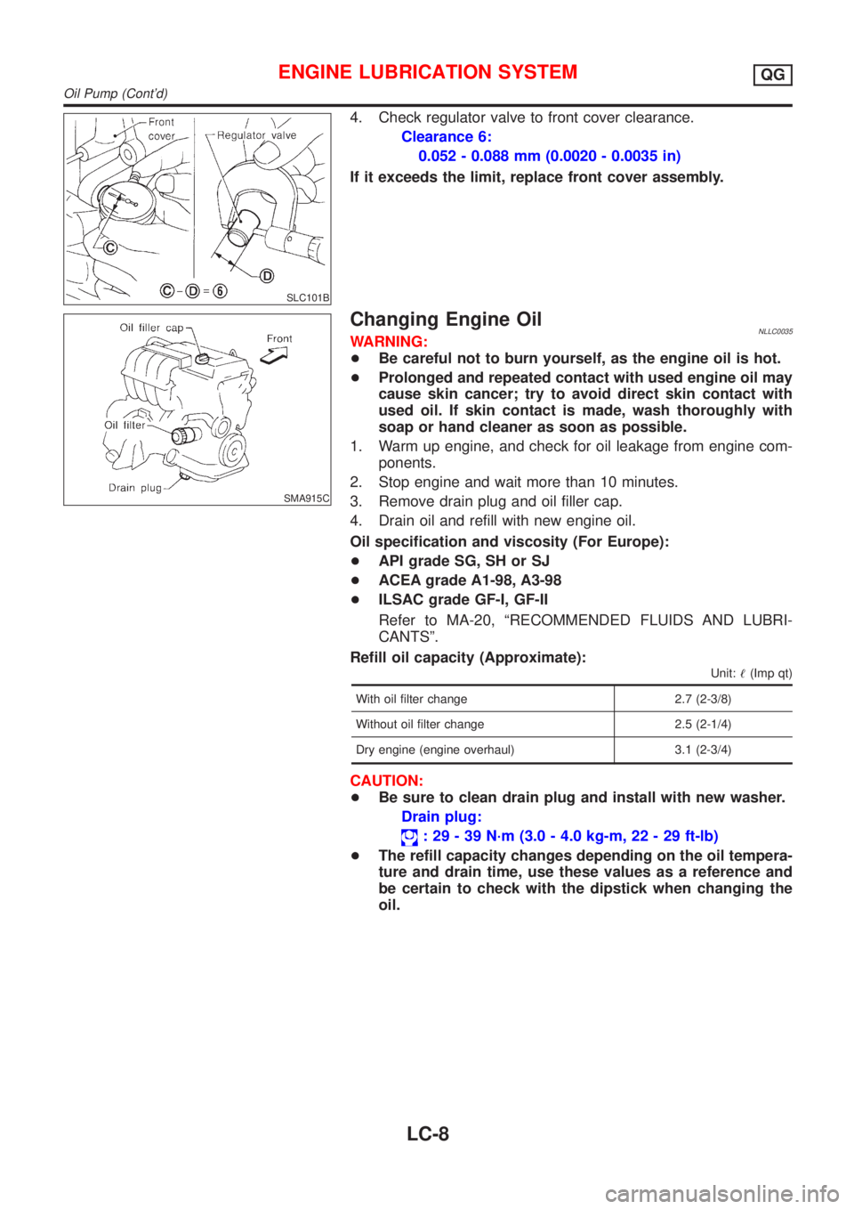
4. Check regulator valve to front cover clearance.
Clearance 6:
0.052 - 0.088 mm (0.0020 - 0.0035 in)
If it exceeds the limit, replace front cover assembly.
SMA915C
Changing Engine OilNLLC0035WARNING:
+Be careful not to burn yourself, as the engine oil is hot.
+Prolonged and repeated contact with used engine oil may
cause skin cancer; try to avoid direct skin contact with
used oil. If skin contact is made, wash thoroughly with
soap or hand cleaner as soon as possible.
1. Warm up engine, and check for oil leakage from engine com-
ponents.
2. Stop engine and wait more than 10 minutes.
3. Remove drain plug and oil filler cap.
4. Drain oil and refill with new engine oil.
Oil specification and viscosity (For Europe):
+API grade SG, SH or SJ
+ACEA grade A1-98, A3-98
+ILSAC grade GF-I, GF-II
Refer to MA-20, ªRECOMMENDED FLUIDS AND LUBRI-
CANTSº.
Refill oil capacity (Approximate):
Unit:!(Imp qt)
With oil filter change 2.7 (2-3/8)
Without oil filter change 2.5 (2-1/4)
Dry engine (engine overhaul) 3.1 (2-3/4)
CAUTION:
+Be sure to clean drain plug and install with new washer.
Drain plug:
: 29 - 39 N´m (3.0 - 4.0 kg-m, 22 - 29 ft-lb)
+The refill capacity changes depending on the oil tempera-
ture and drain time, use these values as a reference and
be certain to check with the dipstick when changing the
oil.
ENGINE LUBRICATION SYSTEMQG
Oil Pump (Cont'd)
LC-8
Page 2712 of 3051
SMA390C
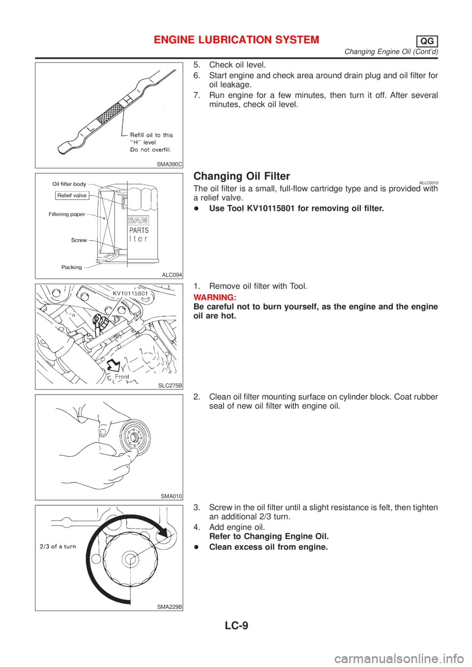
5. Check oil level.
6. Start engine and check area around drain plug and oil filter for
oil leakage.
7. Run engine for a few minutes, then turn it off. After several
minutes, check oil level.
ALC094
Changing Oil FilterNLLC0010The oil filter is a small, full-flow cartridge type and is provided with
a relief valve.
+Use Tool KV10115801 for removing oil filter.
SLC275B
1. Remove oil filter with Tool.
WARNING:
Be careful not to burn yourself, as the engine and the engine
oil are hot.
SMA010
2. Clean oil filter mounting surface on cylinder block. Coat rubber
seal of new oil filter with engine oil.
SMA229B
3. Screw in the oil filter until a slight resistance is felt, then tighten
an additional 2/3 turn.
4. Add engine oil.
Refer to Changing Engine Oil.
+Clean excess oil from engine.
ENGINE LUBRICATION SYSTEMQG
Changing Engine Oil (Cont'd)
LC-9
Page 2715 of 3051
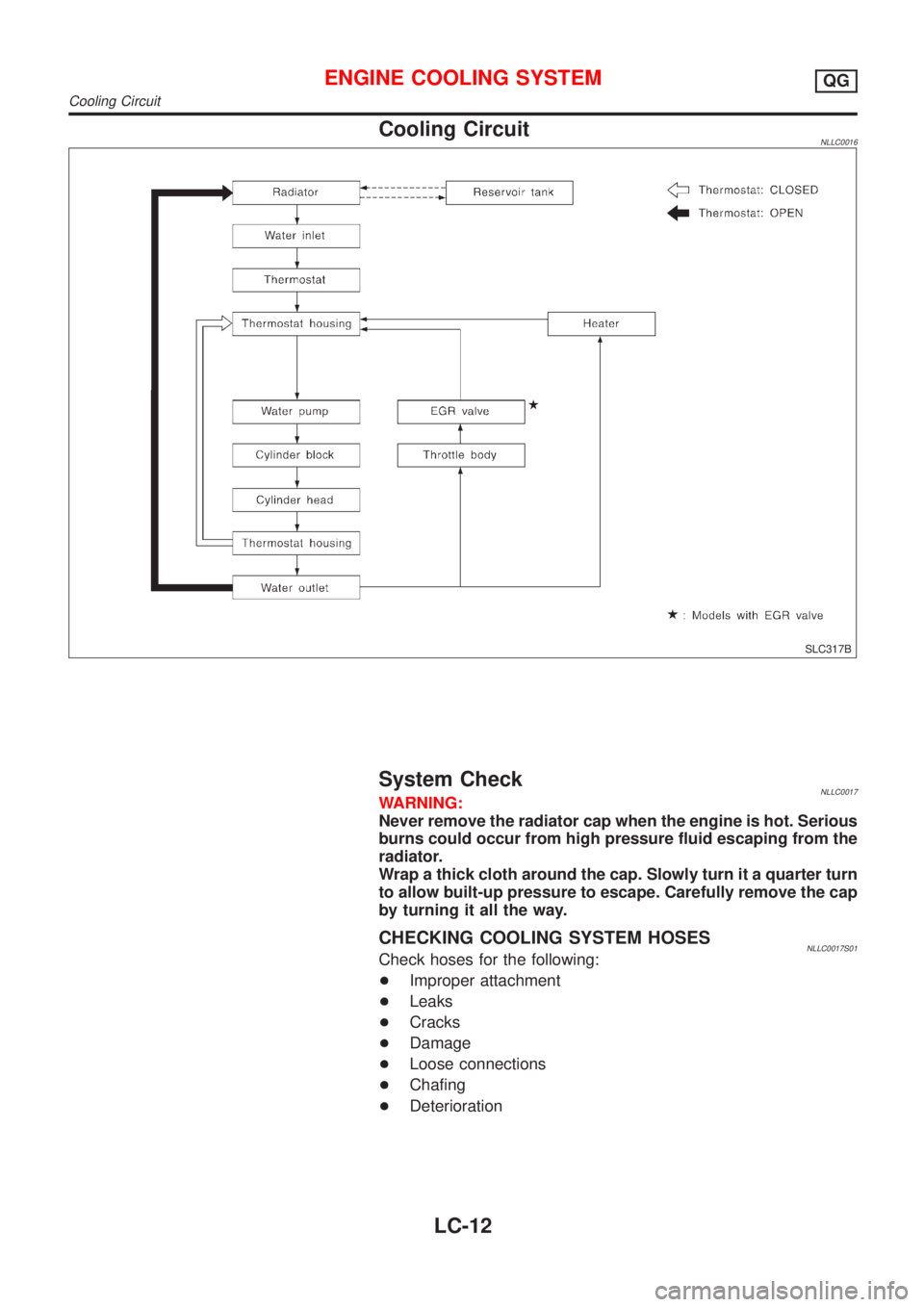
Cooling CircuitNLLC0016
SLC317B
System CheckNLLC0017WARNING:
Never remove the radiator cap when the engine is hot. Serious
burns could occur from high pressure fluid escaping from the
radiator.
Wrap a thick cloth around the cap. Slowly turn it a quarter turn
to allow built-up pressure to escape. Carefully remove the cap
by turning it all the way.
CHECKING COOLING SYSTEM HOSESNLLC0017S01Check hoses for the following:
+Improper attachment
+Leaks
+Cracks
+Damage
+Loose connections
+Chafing
+Deterioration
ENGINE COOLING SYSTEMQG
Cooling Circuit
LC-12