Page 1175 of 3051

Diagnostic ProcedureNLEC1461
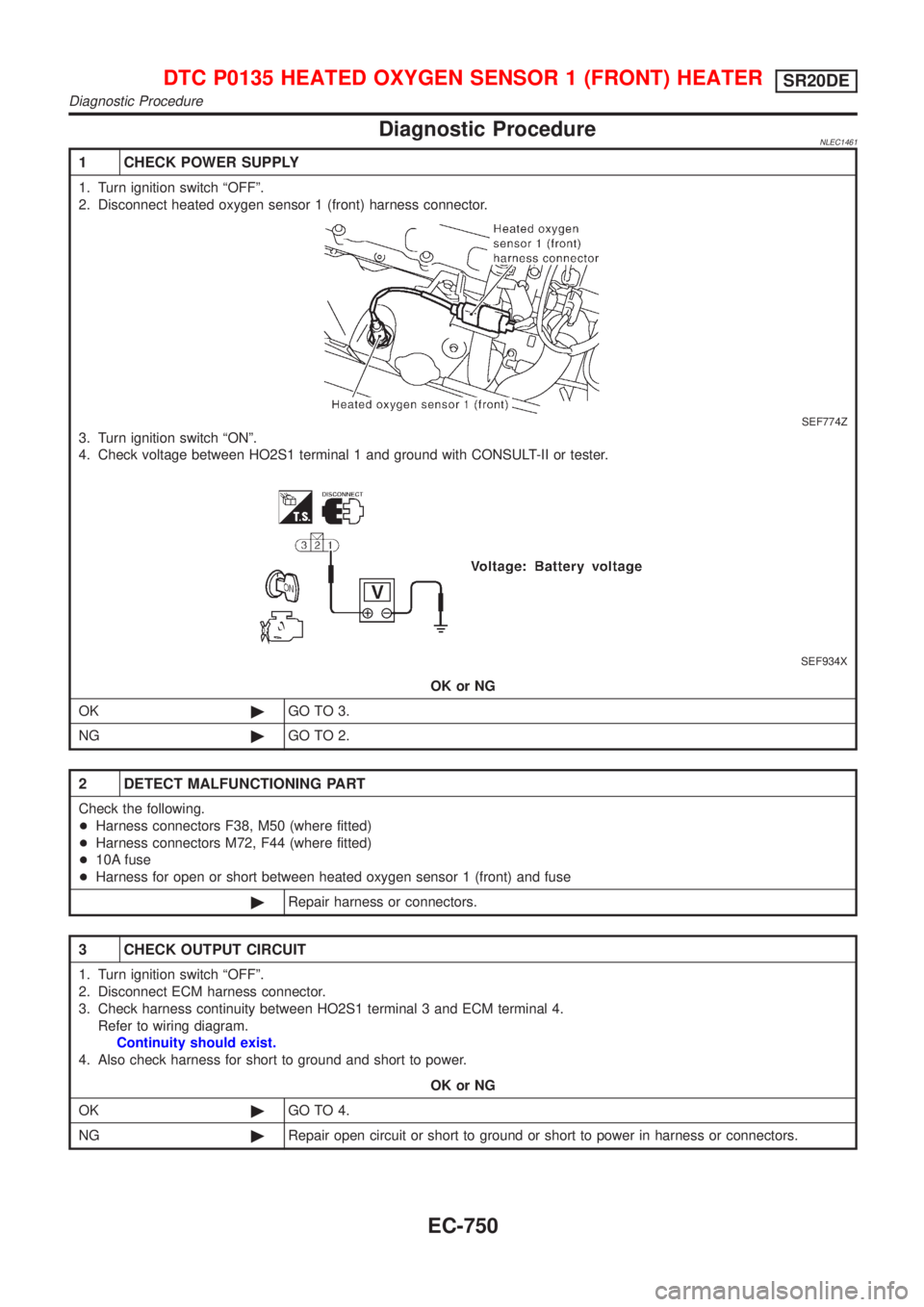
1 CHECK POWER SUPPLY
1. Turn ignition switch ªOFFº.
2. Disconnect heated oxygen sensor 1 (front) harness connector.
SEF774Z
3. Turn ignition switch ªONº.
4. Check voltage between HO2S1 terminal 1 and ground with CONSULT-II or tester.
SEF934X
OK or NG
OK©GO TO 3.
NG©GO TO 2.
2 DETECT MALFUNCTIONING PART
Check the following.
+Harness connectors F38, M50 (where fitted)
+Harness connectors M72, F44 (where fitted)
+10A fuse
+Harness for open or short between heated oxygen sensor 1 (front) and fuse
©Repair harness or connectors.
3 CHECK OUTPUT CIRCUIT
1. Turn ignition switch ªOFFº.
2. Disconnect ECM harness connector.
3. Check harness continuity between HO2S1 terminal 3 and ECM terminal 4.
Refer to wiring diagram.
Continuity should exist.
4. Also check harness for short to ground and short to power.
OK or NG
OK©GO TO 4.
NG©Repair open circuit or short to ground or short to power in harness or connectors.
DTC P0135 HEATED OXYGEN SENSOR 1 (FRONT) HEATERSR20DE
Diagnostic Procedure
EC-750
Page 1180 of 3051
Wiring DiagramNLEC1469MODELS WITH ECM IN ENGINE COMPARTMENTNLEC1469S03
YEC693
DTC P0137 HEATED OXYGEN SENSOR 2 (REAR) (MIN. VOLTAGE
MONITORING)
SR20DE
Wiring Diagram
EC-755
Page 1181 of 3051
MODELS WITH ECM IN CABINNLEC1469S04
YEC918
DTC P0137 HEATED OXYGEN SENSOR 2 (REAR) (MIN. VOLTAGE
MONITORING)
SR20DE
Wiring Diagram (Cont'd)
EC-756
Page 1184 of 3051

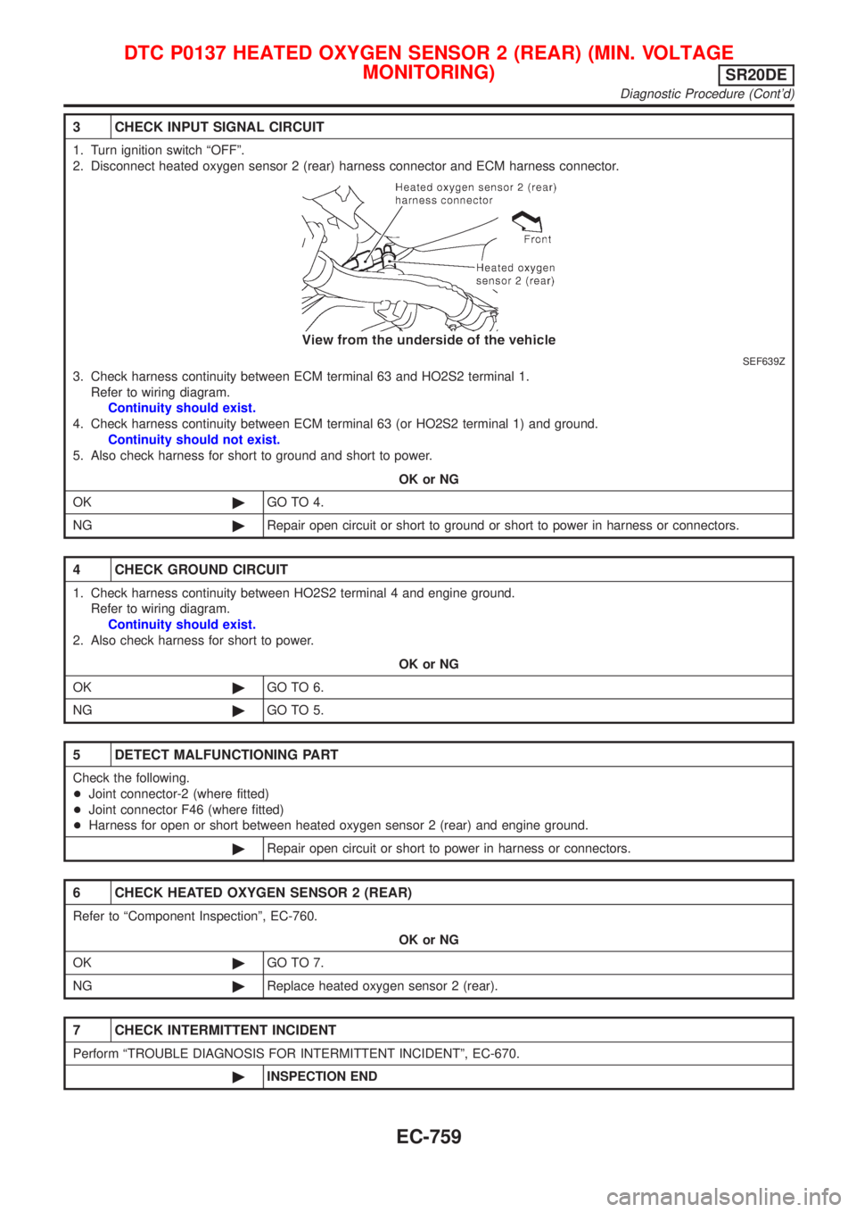
3 CHECK INPUT SIGNAL CIRCUIT
1. Turn ignition switch ªOFFº.
2. Disconnect heated oxygen sensor 2 (rear) harness connector and ECM harness connector.
SEF639Z
3. Check harness continuity between ECM terminal 63 and HO2S2 terminal 1.
Refer to wiring diagram.
Continuity should exist.
4. Check harness continuity between ECM terminal 63 (or HO2S2 terminal 1) and ground.
Continuity should not exist.
5. Also check harness for short to ground and short to power.
OK or NG
OK©GO TO 4.
NG©Repair open circuit or short to ground or short to power in harness or connectors.
4 CHECK GROUND CIRCUIT
1. Check harness continuity between HO2S2 terminal 4 and engine ground.
Refer to wiring diagram.
Continuity should exist.
2. Also check harness for short to power.
OK or NG
OK©GO TO 6.
NG©GO TO 5.
5 DETECT MALFUNCTIONING PART
Check the following.
+Joint connector-2 (where fitted)
+Joint connector F46 (where fitted)
+Harness for open or short between heated oxygen sensor 2 (rear) and engine ground.
©Repair open circuit or short to power in harness or connectors.
6 CHECK HEATED OXYGEN SENSOR 2 (REAR)
Refer to ªComponent Inspectionº, EC-760.
OK or NG
OK©GO TO 7.
NG©Replace heated oxygen sensor 2 (rear).
7 CHECK INTERMITTENT INCIDENT
Perform ªTROUBLE DIAGNOSIS FOR INTERMITTENT INCIDENTº, EC-670.
©INSPECTION END
DTC P0137 HEATED OXYGEN SENSOR 2 (REAR) (MIN. VOLTAGE
MONITORING)
SR20DE
Diagnostic Procedure (Cont'd)
EC-759
Page 1189 of 3051
Wiring DiagramNLEC1478MODELS WITH ECM IN ENGINE COMPARTMENTNLEC1478S03
YEC693
DTC P0138 HEATED OXYGEN SENSOR 2 (REAR) (MAX. VOLTAGE
MONITORING)
SR20DE
Wiring Diagram
EC-764
Page 1190 of 3051
MODELS WITH ECM IN CABINNLEC1478S04
YEC918
DTC P0138 HEATED OXYGEN SENSOR 2 (REAR) (MAX. VOLTAGE
MONITORING)
SR20DE
Wiring Diagram (Cont'd)
EC-765
Page 1193 of 3051

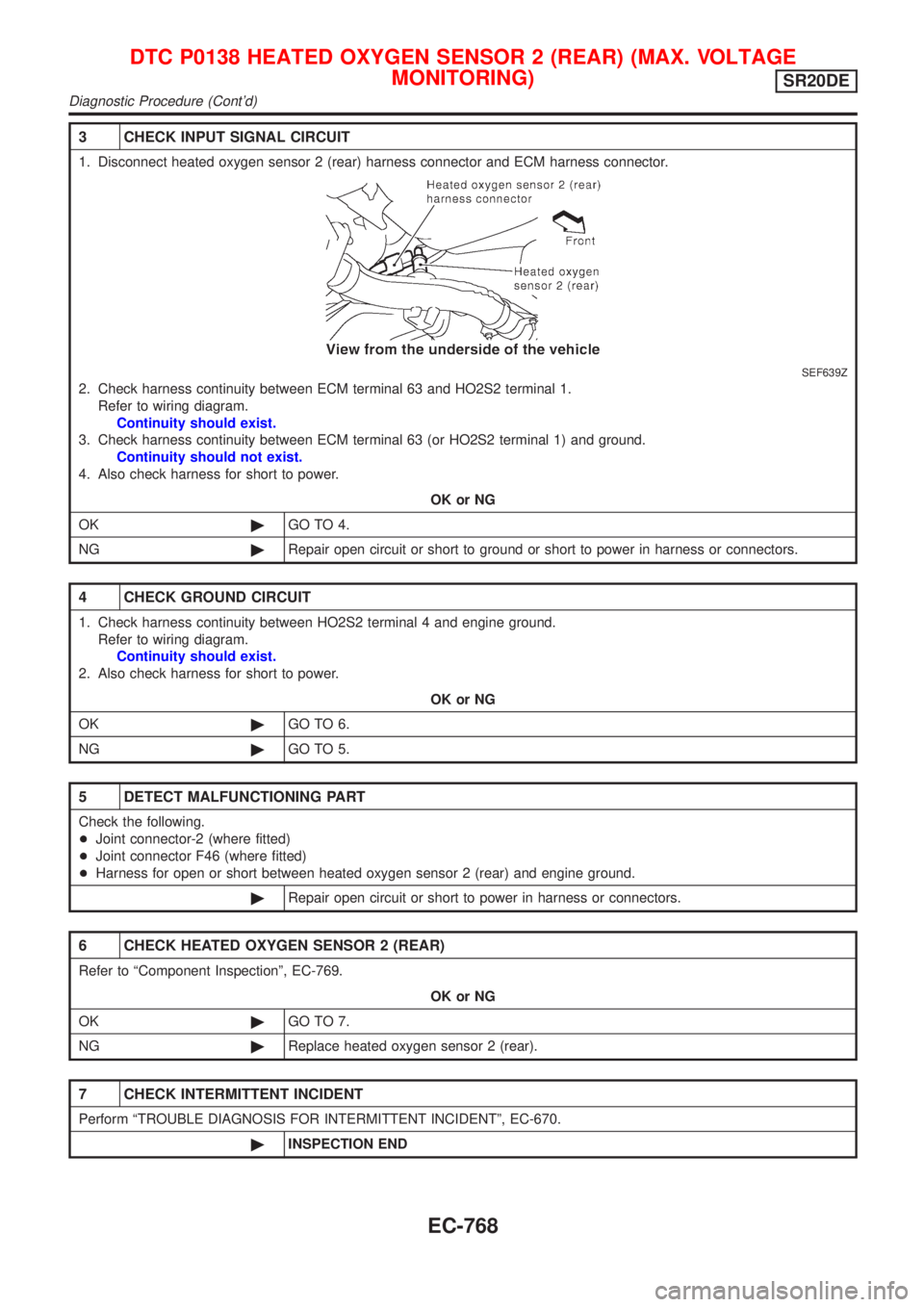
3 CHECK INPUT SIGNAL CIRCUIT
1. Disconnect heated oxygen sensor 2 (rear) harness connector and ECM harness connector.
SEF639Z
2. Check harness continuity between ECM terminal 63 and HO2S2 terminal 1.
Refer to wiring diagram.
Continuity should exist.
3. Check harness continuity between ECM terminal 63 (or HO2S2 terminal 1) and ground.
Continuity should not exist.
4. Also check harness for short to power.
OK or NG
OK©GO TO 4.
NG©Repair open circuit or short to ground or short to power in harness or connectors.
4 CHECK GROUND CIRCUIT
1. Check harness continuity between HO2S2 terminal 4 and engine ground.
Refer to wiring diagram.
Continuity should exist.
2. Also check harness for short to power.
OK or NG
OK©GO TO 6.
NG©GO TO 5.
5 DETECT MALFUNCTIONING PART
Check the following.
+Joint connector-2 (where fitted)
+Joint connector F46 (where fitted)
+Harness for open or short between heated oxygen sensor 2 (rear) and engine ground.
©Repair open circuit or short to power in harness or connectors.
6 CHECK HEATED OXYGEN SENSOR 2 (REAR)
Refer to ªComponent Inspectionº, EC-769.
OK or NG
OK©GO TO 7.
NG©Replace heated oxygen sensor 2 (rear).
7 CHECK INTERMITTENT INCIDENT
Perform ªTROUBLE DIAGNOSIS FOR INTERMITTENT INCIDENTº, EC-670.
©INSPECTION END
DTC P0138 HEATED OXYGEN SENSOR 2 (REAR) (MAX. VOLTAGE
MONITORING)
SR20DE
Diagnostic Procedure (Cont'd)
EC-768
Page 1198 of 3051
Wiring DiagramNLEC1487MODELS WITH ECM IN ENGINE COMPARTMENTNLEC1487S03
YEC693
DTC P0139 HEATED OXYGEN SENSOR 2 (REAR)
(RESPONSE MONITORING)
SR20DE
Wiring Diagram
EC-773