Page 1157 of 3051
Wiring DiagramNLEC1444MODELS WITH ECM IN ENGINE COMPARTMENTNLEC1444S03
YEC691
DTC P0133 HEATED OXYGEN SENSOR 1 (FRONT)
(RESPONSE MONITORING)
SR20DE
Wiring Diagram
EC-732
Page 1158 of 3051
MODELS WITH ECM IN CABINNLEC1444S04
YEC916
DTC P0133 HEATED OXYGEN SENSOR 1 (FRONT)
(RESPONSE MONITORING)
SR20DE
Wiring Diagram (Cont'd)
EC-733
Page 1160 of 3051

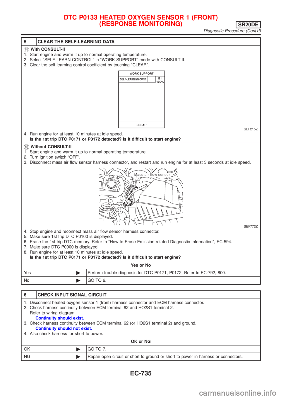
5 CLEAR THE SELF-LEARNING DATA
With CONSULT-II
1. Start engine and warm it up to normal operating temperature.
2. Select ªSELF-LEARN CONTROLº in ªWORK SUPPORTº mode with CONSULT-II.
3. Clear the self-learning control coefficient by touching ªCLEARº.
SEF215Z
4. Run engine for at least 10 minutes at idle speed.
Is the 1st trip DTC P0171 or P0172 detected? Is it difficult to start engine?
Without CONSULT-II
1. Start engine and warm it up to normal operating temperature.
2. Turn ignition switch ªOFFº.
3. Disconnect mass air flow sensor harness connector, and restart and run engine for at least 3 seconds at idle speed.
SEF772Z
4. Stop engine and reconnect mass air flow sensor harness connector.
5. Make sure 1st trip DTC P0100 is displayed.
6. Erase the 1st trip DTC memory. Refer to ªHow to Erase Emission-related Diagnostic Informationº, EC-594.
7. Make sure DTC P0000 is displayed.
8. Run engine for at least 10 minutes at idle speed.
Is the 1st trip DTC P0171 or P0172 detected? Is it difficult to start engine?
YesorNo
Ye s©Perform trouble diagnosis for DTC P0171, P0172. Refer to EC-792, 800.
No©GO TO 6.
6 CHECK INPUT SIGNAL CIRCUIT
1. Disconnect heated oxygen sensor 1 (front) harness connector and ECM harness connector.
2. Check harness continuity between ECM terminal 62 and HO2S1 terminal 2.
Refer to wiring diagram.
Continuity should exist.
3. Check harness continuity between ECM terminal 62 (or HO2S1 terminal 2) and ground.
Continuity should not exist.
4. Also check harness for short to power.
OK or NG
OK©GO TO 7.
NG©Repair open circuit or short to ground or short to power in harness or connectors.
DTC P0133 HEATED OXYGEN SENSOR 1 (FRONT)
(RESPONSE MONITORING)
SR20DE
Diagnostic Procedure (Cont'd)
EC-735
Page 1166 of 3051
Wiring DiagramNLEC1452MODELS WITH ECM IN ENGINE COMPARTMENTNLEC1452S03
YEC691
DTC P0134 HEATED OXYGEN SENSOR 1 (FRONT)
(HIGH VOLTAGE)
SR20DE
Wiring Diagram
EC-741
Page 1167 of 3051
MODELS WITH ECM IN CABINNLEC1452S04
YEC916
DTC P0134 HEATED OXYGEN SENSOR 1 (FRONT)
(HIGH VOLTAGE)
SR20DE
Wiring Diagram (Cont'd)
EC-742
Page 1168 of 3051

Diagnostic ProcedureNLEC1453
1 RETIGHTEN HEATED OXYGEN SENSOR 1 (FRONT)
Loosen and retighten heated oxygen sensor 1 (front).
Tightening torque:
40 - 60 N´m (4.1 - 6.1 kg-m, 30 - 44 ft-lb)
©GO TO 2.
2 CHECK INPUT SIGNAL CIRCUIT
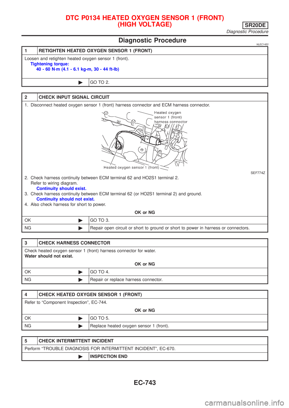
1. Disconnect heated oxygen sensor 1 (front) harness connector and ECM harness connector.
SEF774Z
2. Check harness continuity between ECM terminal 62 and HO2S1 terminal 2.
Refer to wiring diagram.
Continuity should exist.
3. Check harness continuity between ECM terminal 62 (or HO2S1 terminal 2) and ground.
Continuity should not exist.
4. Also check harness for short to power.
OK or NG
OK©GO TO 3.
NG©Repair open circuit or short to ground or short to power in harness or connectors.
3 CHECK HARNESS CONNECTOR
Check heated oxygen sensor 1 (front) harness connector for water.
Water should not exist.
OK or NG
OK©GO TO 4.
NG©Repair or replace harness connector.
4 CHECK HEATED OXYGEN SENSOR 1 (FRONT)
Refer to ªComponent Inspectionº, EC-744.
OK or NG
OK©GO TO 5.
NG©Replace heated oxygen sensor 1 (front).
5 CHECK INTERMITTENT INCIDENT
Perform ªTROUBLE DIAGNOSIS FOR INTERMITTENT INCIDENTº, EC-670.
©INSPECTION END
DTC P0134 HEATED OXYGEN SENSOR 1 (FRONT)
(HIGH VOLTAGE)
SR20DE
Diagnostic Procedure
EC-743
Page 1173 of 3051
Wiring DiagramNLEC1460MODELS WITH ECM IN ENGINE COMPARTMENTNLEC1460S03
YEC692
DTC P0135 HEATED OXYGEN SENSOR 1 (FRONT) HEATERSR20DE
Wiring Diagram
EC-748
Page 1174 of 3051
MODELS WITH ECM IN CABINNLEC1460S04
YEC917
DTC P0135 HEATED OXYGEN SENSOR 1 (FRONT) HEATERSR20DE
Wiring Diagram (Cont'd)
EC-749