Page 1110 of 3051

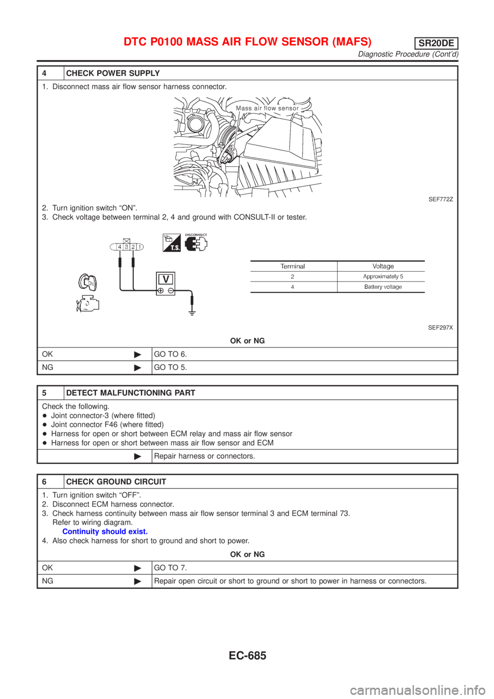
4 CHECK POWER SUPPLY
1. Disconnect mass air flow sensor harness connector.
SEF772Z
2. Turn ignition switch ªONº.
3. Check voltage between terminal 2, 4 and ground with CONSULT-II or tester.
SEF297X
OK or NG
OK©GO TO 6.
NG©GO TO 5.
5 DETECT MALFUNCTIONING PART
Check the following.
+Joint connector-3 (where fitted)
+Joint connector F46 (where fitted)
+Harness for open or short between ECM relay and mass air flow sensor
+Harness for open or short between mass air flow sensor and ECM
©Repair harness or connectors.
6 CHECK GROUND CIRCUIT
1. Turn ignition switch ªOFFº.
2. Disconnect ECM harness connector.
3. Check harness continuity between mass air flow sensor terminal 3 and ECM terminal 73.
Refer to wiring diagram.
Continuity should exist.
4. Also check harness for short to ground and short to power.
OK or NG
OK©GO TO 7.
NG©Repair open circuit or short to ground or short to power in harness or connectors.
DTC P0100 MASS AIR FLOW SENSOR (MAFS)SR20DE
Diagnostic Procedure (Cont'd)
EC-685
Page 1111 of 3051

7 CHECK INPUT SIGNAL CIRCUIT
1. Check harness continuity between mass air flow sensor terminal 1 and ECM terminal 61.
Refer to wiring diagram.
Continuity should exist.
2. Also check harness for short to ground and short to power.
OK or NG
OK©GO TO 8.
NG©Repair open circuit or short to ground or short to power in harness or connectors.
8 CHECK MASS AIR FLOW SENSOR
Refer to ªComponent Inspectionº, EC-686.
OK or NG
OK©GO TO 9.
NG©Replace mass air flow sensor.
9 CHECK INTERMITTENT INCIDENT
Perform ªTROUBLE DIAGNOSIS FOR INTERMITTENT INCIDENTº, EC-670.
©INSPECTION END
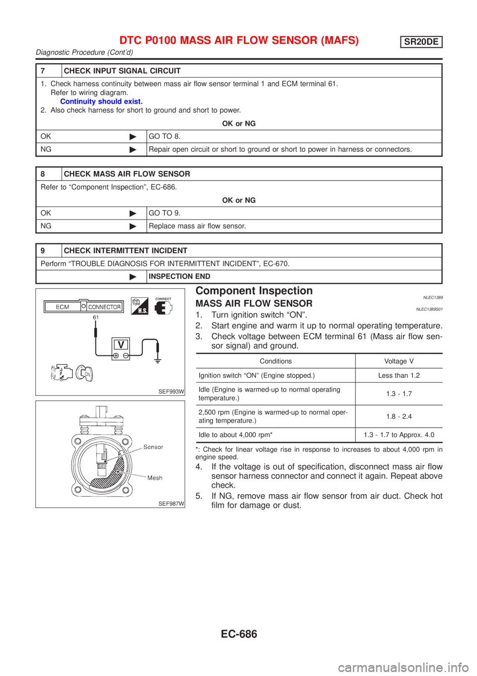
SEF993W
SEF987W
Component InspectionNLEC1389MASS AIR FLOW SENSORNLEC1389S011. Turn ignition switch ªONº.
2. Start engine and warm it up to normal operating temperature.
3. Check voltage between ECM terminal 61 (Mass air flow sen-
sor signal) and ground.
Conditions Voltage V
Ignition switch ªONº (Engine stopped.) Less than 1.2
Idle (Engine is warmed-up to normal operating
temperature.)1.3 - 1.7
2,500 rpm (Engine is warmed-up to normal oper-
ating temperature.)1.8 - 2.4
Idle to about 4,000 rpm* 1.3 - 1.7 to Approx. 4.0
*: Check for linear voltage rise in response to increases to about 4,000 rpm in
engine speed.
4. If the voltage is out of specification, disconnect mass air flow
sensor harness connector and connect it again. Repeat above
check.
5. If NG, remove mass air flow sensor from air duct. Check hot
film for damage or dust.
DTC P0100 MASS AIR FLOW SENSOR (MAFS)SR20DE
Diagnostic Procedure (Cont'd)
EC-686
Page 1114 of 3051
Wiring DiagramNLEC1393MODELS WITH INTAKE AIR TEMPERATURE SENSOR
ON INTAKE AIR DUCT
NLEC1391S01
YEC688
DTC P0110 INTAKE AIR TEMPERATURE SENSORSR20DE
Wiring Diagram
EC-689
Page 1115 of 3051
MODELS WITH INTAKE AIR TEMPERATURE SENSOR
IN MASS AIR FLOW SENSOR
NLEC1391S02
YEC913
DTC P0110 INTAKE AIR TEMPERATURE SENSORSR20DE
Wiring Diagram (Cont'd)
EC-690
Page 1117 of 3051
1 CHECK POWER SUPPLY (MODELS WITH INTAKE AIR TEMPERATURE SENSOR IN MASS AIR FLOW
SENSOR)
1. Turn ignition switch ªOFFº.
2. Disconnect intake air temperature sensor (mass air flow sensor) harness connector.
NEF306A
3. Turn ignition switch ªONº.
4. Check voltage between terminal 5 and ground with CONSULT-II or tester.
NEF307A
OK or NG
OK©GO TO 3.
NG©GO TO 2.
2 DETECT MALFUNCTIONING PART
Check the following.
+Harness connectors E75, F35 (where fitted)
+Harness for open or short between ECM and intake air temperature sensor
©Repair harness or connectors.
3 CHECK GROUND CIRCUIT
1. Turn ignition switch ªOFFº.
2. Check harness continuity between intake air temperature sensor ground terminal and engine ground.
Refer to wiring diagram.
Continuity should exist.
3. Also check harness for short to power.
OK or NG
OK©GO TO 5.
NG©GO TO 4.
DTC P0110 INTAKE AIR TEMPERATURE SENSORSR20DE
Diagnostic Procedure (Cont'd)
EC-692
Page 1121 of 3051
Wiring DiagramNLEC1401MODELS WITH ECM IN ENGINE COMPARTMENTNLEC1401S01
YEC689
DTC P0115 ENGINE COOLANT TEMPERATURE SENSOR (ECTS)
(CIRCUIT)
SR20DE
Wiring Diagram
EC-696
Page 1122 of 3051
MODELS WITH ECM IN CABINNLEC1401S02
YEC914
DTC P0115 ENGINE COOLANT TEMPERATURE SENSOR (ECTS)
(CIRCUIT)
SR20DE
Wiring Diagram (Cont'd)
EC-697
Page 1123 of 3051
Diagnostic ProcedureNLEC1402
1 CHECK POWER SUPPLY
1. Turn ignition switch ªOFFº.
2. Disconnect engine coolant temperature sensor harness connector.
SEF773Z
3. Turn ignition switch ªONº.
4. Check voltage between terminal 1 and ground with CONSULT-II or tester.
SEF301X
OK or NG
OK©GO TO 3.
NG©GO TO 2.
2 DETECT MALFUNCTIONING PART
Check the harness for open or short between ECM and engine coolant temperature sensor.
©Repair harness or connectors.
3 CHECK GROUND CIRCUIT
1. Turn ignition switch ªOFFº.
2. Check harness continuity between engine coolant temperature sensor terminal 2 and engine ground.
Refer to wiring diagram.
Continuity should exist.
3. Also check harness for short to power.
OK or NG
OK©GO TO 5.
NG©GO TO 4.
DTC P0115 ENGINE COOLANT TEMPERATURE SENSOR (ECTS)
(CIRCUIT)
SR20DE
Diagnostic Procedure
EC-698