Page 1199 of 3051
MODELS WITH ECM IN CABINNLEC1487S04
YEC918
DTC P0139 HEATED OXYGEN SENSOR 2 (REAR)
(RESPONSE MONITORING)
SR20DE
Wiring Diagram (Cont'd)
EC-774
Page 1202 of 3051

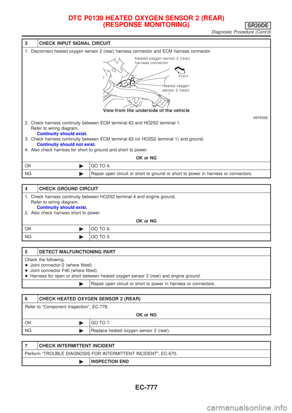
3 CHECK INPUT SIGNAL CIRCUIT
1. Disconnect heated oxygen sensor 2 (rear) harness connector and ECM harness connector.
SEF639Z
2. Check harness continuity between ECM terminal 63 and HO2S2 terminal 1.
Refer to wiring diagram.
Continuity should exist.
3. Check harness continuity between ECM terminal 63 (or HO2S2 terminal 1) and ground.
Continuity should not exist.
4. Also check harness for short to ground and short to power.
OK or NG
OK©GO TO 4.
NG©Repair open circuit or short to ground or short to power in harness or connectors.
4 CHECK GROUND CIRCUIT
1. Check harness continuity between HO2S2 terminal 4 and engine ground.
Refer to wiring diagram.
Continuity should exist.
2. Also check harness short to power.
OK or NG
OK©GO TO 6.
NG©GO TO 5.
5 DETECT MALFUNCTIONING PART
Check the following.
+Joint connector-2 (where fitted)
+Joint connector F46 (where fitted)
+Harness for open or short between heated oxygen sensor 2 (rear) and engine ground.
©Repair open circuit or short to power in harness or connectors.
6 CHECK HEATED OXYGEN SENSOR 2 (REAR)
Refer to ªComponent Inspectionº, EC-778.
OK or NG
OK©GO TO 7.
NG©Replace heated oxygen sensor 2 (rear).
7 CHECK INTERMITTENT INCIDENT
Perform ªTROUBLE DIAGNOSIS FOR INTERMITTENT INCIDENTº, EC-670.
©INSPECTION END
DTC P0139 HEATED OXYGEN SENSOR 2 (REAR)
(RESPONSE MONITORING)
SR20DE
Diagnostic Procedure (Cont'd)
EC-777
Page 1206 of 3051
Wiring DiagramNLEC1496MODELS WITH ECM IN ENGINE COMPARTMENTNLEC1496S03
YEC693
DTC P0140 HEATED OXYGEN SENSOR 2 (REAR)
(HIGH VOLTAGE)
SR20DE
Wiring Diagram
EC-781
Page 1207 of 3051
MODELS WITH ECM IN CABINNLEC1496S04
YEC918
DTC P0140 HEATED OXYGEN SENSOR 2 (REAR)
(HIGH VOLTAGE)
SR20DE
Wiring Diagram (Cont'd)
EC-782
Page 1208 of 3051

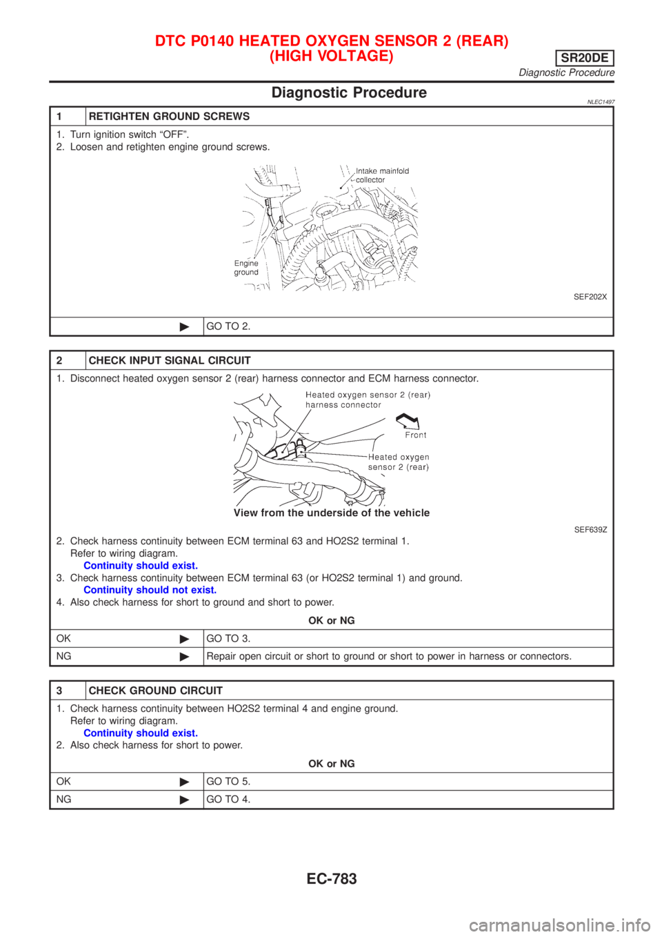
Diagnostic ProcedureNLEC1497
1 RETIGHTEN GROUND SCREWS
1. Turn ignition switch ªOFFº.
2. Loosen and retighten engine ground screws.
SEF202X
©GO TO 2.
2 CHECK INPUT SIGNAL CIRCUIT
1. Disconnect heated oxygen sensor 2 (rear) harness connector and ECM harness connector.
SEF639Z
2. Check harness continuity between ECM terminal 63 and HO2S2 terminal 1.
Refer to wiring diagram.
Continuity should exist.
3. Check harness continuity between ECM terminal 63 (or HO2S2 terminal 1) and ground.
Continuity should not exist.
4. Also check harness for short to ground and short to power.
OK or NG
OK©GO TO 3.
NG©Repair open circuit or short to ground or short to power in harness or connectors.
3 CHECK GROUND CIRCUIT
1. Check harness continuity between HO2S2 terminal 4 and engine ground.
Refer to wiring diagram.
Continuity should exist.
2. Also check harness for short to power.
OK or NG
OK©GO TO 5.
NG©GO TO 4.
DTC P0140 HEATED OXYGEN SENSOR 2 (REAR)
(HIGH VOLTAGE)
SR20DE
Diagnostic Procedure
EC-783
Page 1213 of 3051
Wiring DiagramNLEC1504MODELS WITH ECM IN ENGINE COMARTMENTNLEC1504S03
YEC694
DTC P0141 HEATED OXYGEN SENSOR 2 HEATER (REAR)SR20DE
Wiring Diagram
EC-788
Page 1214 of 3051
MODELS WITH ECM IN CABINNLEC1504S04
YEC919
DTC P0141 HEATED OXYGEN SENSOR 2 HEATER (REAR)SR20DE
Wiring Diagram (Cont'd)
EC-789
Page 1215 of 3051
Diagnostic ProcedureNLEC1505
1 CHECK POWER SUPPLY
1. Turn ignition switch ªOFFº.
2. Disconnect heated oxygen sensor 2 (rear) harness connector.
SEF639Z
3. Turn ignition switch ªONº.
4. Check voltage between HO2S2 terminal 2 and ground.
SEF218W
Voltage: Battery voltage
OK or NG
OK©GO TO 3.
NG©GO TO 2.
2 DETECT MALFUNCTIONING PART
Check the following.
+Harness connectors F38, M50 (where fitted)
+Harness connectors M72, F44 (where fitted)
+Harness for open or short between heated oxygen sensor 2 (rear) and fuse
+10A fuse
©Repair harness or connectors.
3 CHECK OUTPUT CIRCUIT
1. Turn ignition switch ªOFFº.
2. Disconnect ECM harness connector.
3. Check harness continuity between HO2S2 terminal 3 and ECM terminal 3.
Refer to wiring diagram.
Continuity should exist.
4. Also check harness for short to ground and short to power.
OK or NG
OK©GO TO 5.
NG©GO TO 4.
DTC P0141 HEATED OXYGEN SENSOR 2 HEATER (REAR)SR20DE
Diagnostic Procedure
EC-790