Page 1219 of 3051
Wiring DiagramNLEC1509MODELS WITH ECM IN ENGINE COMPARTMENTNLEC1509S03
YEC695
DTC P0171 FUEL INJECTION SYSTEM FUNCTION
(LEAN SIDE)
SR20DE
Wiring Diagram
EC-794
Page 1220 of 3051
MODELS WITH ECM IN CABINNLEC1509S04
YEC920
DTC P0171 FUEL INJECTION SYSTEM FUNCTION
(LEAN SIDE)
SR20DE
Wiring Diagram (Cont'd)
EC-795
Page 1221 of 3051

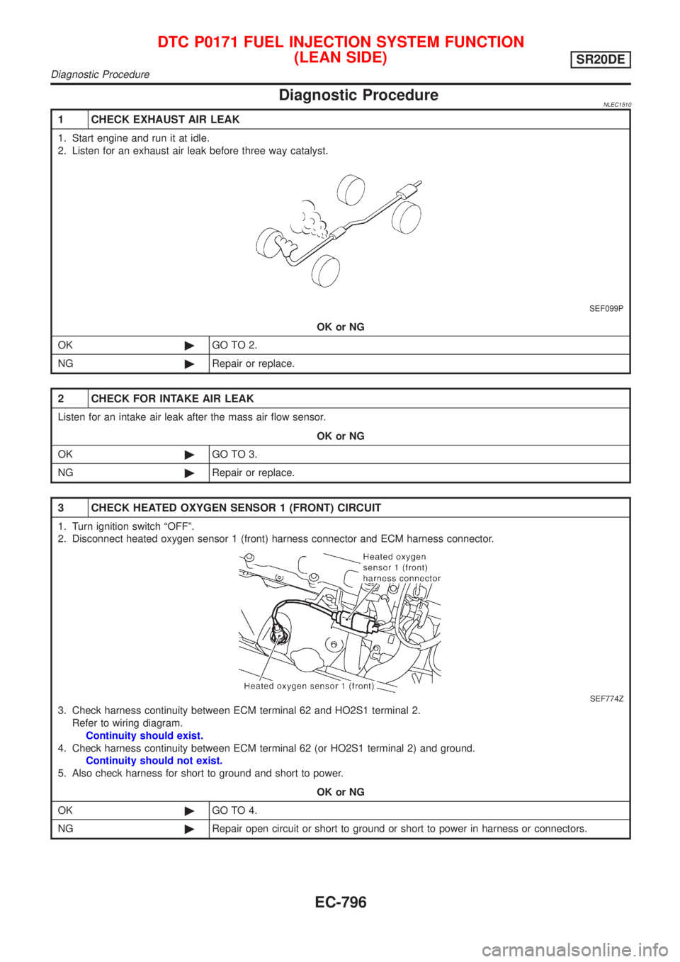
Diagnostic ProcedureNLEC1510
1 CHECK EXHAUST AIR LEAK
1. Start engine and run it at idle.
2. Listen for an exhaust air leak before three way catalyst.
SEF099P
OK or NG
OK©GO TO 2.
NG©Repair or replace.
2 CHECK FOR INTAKE AIR LEAK
Listen for an intake air leak after the mass air flow sensor.
OK or NG
OK©GO TO 3.
NG©Repair or replace.
3 CHECK HEATED OXYGEN SENSOR 1 (FRONT) CIRCUIT
1. Turn ignition switch ªOFFº.
2. Disconnect heated oxygen sensor 1 (front) harness connector and ECM harness connector.
SEF774Z
3. Check harness continuity between ECM terminal 62 and HO2S1 terminal 2.
Refer to wiring diagram.
Continuity should exist.
4. Check harness continuity between ECM terminal 62 (or HO2S1 terminal 2) and ground.
Continuity should not exist.
5. Also check harness for short to ground and short to power.
OK or NG
OK©GO TO 4.
NG©Repair open circuit or short to ground or short to power in harness or connectors.
DTC P0171 FUEL INJECTION SYSTEM FUNCTION
(LEAN SIDE)
SR20DE
Diagnostic Procedure
EC-796
Page 1227 of 3051
Wiring DiagramNLEC1513MODELS WITH ECM IN ENGINE COMPARTMENTNLEC1513S03
YEC695
DTC P0172 FUEL INJECTION SYSTEM FUNCTION
(RICH SIDE)
SR20DE
Wiring Diagram
EC-802
Page 1228 of 3051
MODELS WITH ECM IN CABINNLEC1513S04
YEC920
DTC P0172 FUEL INJECTION SYSTEM FUNCTION
(RICH SIDE)
SR20DE
Wiring Diagram (Cont'd)
EC-803
Page 1229 of 3051
Diagnostic ProcedureNLEC1514
1 CHECK FOR EXHAUST AIR LEAK
1. Start engine and run it at idle.
2. Listen for an exhaust air leak before the three way catalyst.
SEF099P
OK or NG
OK©GO TO 2.
NG©Repair or replace.
2 CHECK HEATED OXYGEN SENSOR 1 (FRONT) CIRCUIT
1. Turn ignition switch ªOFFº.
2. Disconnect heated oxygen sensor 1 (front) harness connector and ECM harness connector.
SEF774Z
3. Check harness continuity between ECM terminal 62 and HO2S1 terminal 2.
Refer to wiring diagram.
Continuity should exist.
4. Check harness continuity between ECM terminal 62 (or HO2S1 terminal 2) and ground.
Continuity should not exist.
5. Also check harness for short to ground and short to power.
OK or NG
OK©GO TO 3.
NG©Repair open circuit or short to ground or short to power in harness or connectors.
DTC P0172 FUEL INJECTION SYSTEM FUNCTION
(RICH SIDE)
SR20DE
Diagnostic Procedure
EC-804
Page 1241 of 3051
Wiring DiagramNLEC1528
YEC697
DTC P0325 KNOCK SENSOR (KS)SR20DE
Wiring Diagram
EC-816
Page 1242 of 3051
Diagnostic ProcedureNLEC1529
1 RETIGHTEN GROUND SCREWS
Loosen and retighten engine ground screws.
SEF202X
©GO TO 2.
2 CHECK INPUT SIGNAL CIRCUIT-1
1. Turn ignition switch ªOFFº.
2. Disconnect ECM harness connector and knock sensor harness connector.
SEF776Z
3. Check harness continuity between knock sensor terminal 1 and ECM terminal 81.
Refer to wiring diagram.
Continuity should exist.
4. Also check harness for short to ground and short to power.
OK or NG
OK©GO TO 4.
NG©GO TO 3.
3 DETECT MALFUNCTIONING PART
Check the following.
+Harness connectors F21, F101
+Harness for open or short between knock sensor and ECM.
©Repair open circuit or short to ground or short to power in harness or connectors.
4 CHECK KNOCK SENSOR
Refer to ªComponent Inspectionº, EC-818.
OK or NG
OK©GO TO 5.
NG©Replace knock sensor.
DTC P0325 KNOCK SENSOR (KS)SR20DE
Diagnostic Procedure
EC-817