Page 1243 of 3051
5 CHECK SHIELD CIRCUIT
1. Reconnect harness connectors disconnected.
2. Disconnect harness connectors F21, F101.
3. Check harness continuity between F21 terminal 2 and engine ground.
Refer to wiring diagram.
Continuity should exist.
4. Also check harness for short to power.
5. Then reconnect harness connectors.
OK or NG
OK©GO TO 6.
NG©Repair open circuit or short to power in harness or connectors.
6 CHECK INTERMITTENT INCIDENT
Perform ªTROUBLE DIAGNOSIS FOR INTERMITTENT INCIDENTº, EC-670.
©INSPECTION END
SEF227W
Component InspectionNLEC1530KNOCK SENSORNLEC1530S01+Use an ohmmeter which can measure more than 10 MW.
1. Disconnect knock sensor harness connector.
2. Check resistance between terminal 1 and ground.
Resistance: 500 - 620 kW[at 25ÉC (77ÉF)]
CAUTION:
Discard any knock sensors that have been dropped or physi-
cally damaged. Use only new ones.
DTC P0325 KNOCK SENSOR (KS)SR20DE
Diagnostic Procedure (Cont'd)
EC-818
Page 1246 of 3051
Wiring DiagramNLEC1758MODELS WITH ECM IN ENGINE COMPARTMENTNLEC1758S01
YEC698
DTC P0335 CRANKSHAFT POSITION SENSOR (CKPS) (OBD)SR20DE
Wiring Diagram
EC-821
Page 1247 of 3051
MODELS WITH ECM IN CABINNLEC1758S02
YEC921
DTC P0335 CRANKSHAFT POSITION SENSOR (CKPS) (OBD)SR20DE
Wiring Diagram (Cont'd)
EC-822
Page 1248 of 3051
Diagnostic ProcedureNLEC1759
1 RETIGHTEN GROUND SCREWS
1. Turn ignition switch ªOFFº.
2. Loosen and retighten engine ground screws.
SEF202X
©GO TO 2.
2 CHECK INPUT SIGNAL CIRCUIT
1. Disconnect crankshaft position sensor (OBD) and ECM harness connectors.
SEF777Z
2. Check continuity between ECM terminal 65 and CKPS (OBD) terminal 1.
Refer to Wiring Diagram.
Continuity should exist.
3. Also check harness for short to ground and short to power.
OK or NG
OK©GO TO 4.
NG©GO TO 3.
3 DETECT MALFUNCTIONING PART
Check the harness for open or short between crankshaft position sensor (OBD) and ECM
©Repair open circuit or short to ground or short to power in harness or connectors.
DTC P0335 CRANKSHAFT POSITION SENSOR (CKPS) (OBD)SR20DE
Diagnostic Procedure
EC-823
Page 1253 of 3051
Wiring DiagramNLEC1765MODELS WITH ECM IN ENGINE COMPARTMENTNLEC1765S01
YEC699
DTC P0340 CAMSHAFT POSITION SENSOR (CMPS)SR20DE
Wiring Diagram
EC-828
Page 1254 of 3051
MODELS WITH ECM IN CABINNLEC1765S02
YEC922
DTC P0340 CAMSHAFT POSITION SENSOR (CMPS)SR20DE
Wiring Diagram (Cont'd)
EC-829
Page 1256 of 3051

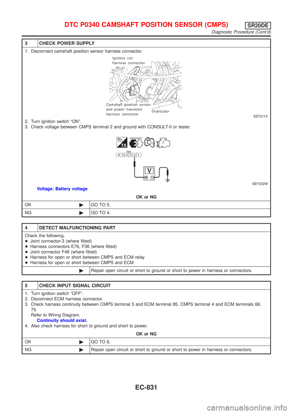
3 CHECK POWER SUPPLY
1. Disconnect camshaft position sensor harness connector.
SEF211X
2. Turn ignition switch ªONº.
3. Check voltage between CMPS terminal 2 and ground with CONSULT-II or tester.
SEF232W
Voltage: Battery voltage
OK or NG
OK©GO TO 5.
NG©GO TO 4.
4 DETECT MALFUNCTIONING PART
Check the following.
+Joint connector-3 (where fitted)
+Harness connectors E76, F36 (where fitted)
+Joint connector F46 (where fitted)
+Harness for open or short between CMPS and ECM relay
+Harness for open or short between CMPS and ECM
©Repair open circuit or short to ground or short to power in harness or connectors.
5 CHECK INPUT SIGNAL CIRCUIT
1. Turn ignition switch ªOFFº.
2. Disconnect ECM harness connector.
3. Check harness continuity between CMPS terminal 3 and ECM terminal 85, CMPS terminal 4 and ECM terminals 66,
75.
Refer to Wiring Diagram.
Continuity should exist.
4. Also check harness for short to ground and short to power.
OK or NG
OK©GO TO 6.
NG©Repair open circuit or short to ground or short to power in harness or connectors.
DTC P0340 CAMSHAFT POSITION SENSOR (CMPS)SR20DE
Diagnostic Procedure (Cont'd)
EC-831
Page 1263 of 3051
Wiring DiagramNLEC1550
YEC700
DTC P0400 EGR FUNCTION (CLOSED) (WHERE FITTED)SR20DE
Wiring Diagram
EC-838